1
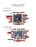
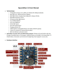
Open Sprinkler User Manual RAYSHOBBY.NET Ray's DIY Electronics Hobby Projects Page 1 Contents RAYSHOBBY.NET ..................................................................................................................................... 1 Hardware Interface ....................................................................................................................................... 3 Official Fully Assembled v2.0s ................................................................................................................... 3 DIY v1.42u ................................................................................................................................................. 3 Power Supply Requirements ......................................................................................................................... 4 Wire Sprinkler Valve...................................................................................................................................... 4 Set Up Options .............................................................................................................................................. 5 Change the controller options /settings ................................................................................................... 5 List of Options (Firmware 1.8.3 and 2.0.3) ............................................................................................... 5 Self-test ..................................................................................................................................................... 7 Reset ......................................................................................................................................................... 7 Network Connection Choices........................................................................................................................ 7 Wired Connection ..................................................................................................................................... 7 WiFi Connection ........................................................................................................................................ 7 Port forwarding ......................................................................................................................................... 8 Button Functions – Normal Operations ........................................................................................................ 8 LCD Display.................................................................................................................................................... 9 Connecting to Rain Sensor .......................................................................................................................... 10 CONTROLLER QUICK REFERENCE GUIDE ..................................................................................................... 11 OpenSprinkler Firmware Update ................................................................................................................ 12 Upload a Precompiled Firmware ............................................................................................................ 12 Driver Installation.................................................................................................................................... 13 Compile and Modify the Source Code .................................................................................................... 14 Page 2 Hardware Interface The interface of the controller is shown in the pictures below. The 24VAC power jack, switch, and USB connector are on the left side; the three push buttons and the Ethernet connector are on the right side; the COM (common) terminal and screw terminals for connecting sprinkler wires are on the bottom. Note that the two ports on the COM terminal are internally wired together, so either can be used as the common wire. There are also a rain sensor connector and zone expansion connector. Official Fully Assembled v2.0s DIY v1.42u Page 3 Power Supply Requirements The controller uses a standard 24∼27V AC (note that the output is AC, not DC) sprinkler transformer. Since AC transformers are not regulated, the output may vary anywhere between 22V AC to 29V AC. The current rating should be at least 500mA (12VA). Sprinkler transformers can be purchased online (search for sprinkler transformer or 24V AC transformer), or at local home improvement stores. You can also buy a cheap off-the-shelf sprinkler timer which usually comes with a transformer. Warning: DO NOT plug 24VAC into the COM port or the Rain Sensor port! Doing so may damage your transformer or the controller. We recommend using a permanent marker to mark the screw terminal pieces to help you easily identify the two. Also, to reduce the chance of damage due to power surge, please use a surge protector. Update: from version 2.1, the 24VAC terminal has been changed to an orange-colored one with a different pin spacing. This can help prevent mistakes in plugging in power. After connecting the power supply, slide down the power switch. The LCD should turn on and start displaying messages. Wire Sprinkler Valve A sprinkler valve has two wires. Connect one wire to the COM (Common) terminal (either of the two ports), and the other wire to an individual station terminal (S1S8). For multiple valves: one wire from each valve is combined together and goes to the COM terminal, and the other wire of each valve goes to its corresponding station terminal. If you are not sure, ask a landscaper or go to a home improvement store to ask for help. Page 4 Set Up Options The controller is programmed with a list of options. Most of them do not need to be changed. Change the controller options /settings Turn off the controller. Hold pushbutton B3 while starting the controller, until you see the message Setup Options. Click B3 to cycle through all available options, and click B1 or B2 to increase or decrease the value of each option. Note that some options can only be set via the web interface and cannot be changed using buttons. Once you are done, hold B3 again, until the controller restarts. Your changes are now saved and applied. List of Options (Firmware 1.8.3 and 2.0.3) The latest firmware version is 1.8.3 for 1.x hardware, and 2.0.3 for 2.x hardware. The complete list of options are described below: Time Zone: select your time zone (used for NTP time sync and effective only after reboot). NTP Sync: automatic time sync via NTP. Default on. Use DHCP: yes to enable DHCP (i.e. obtain a dynamic IP from your router), no to disable DHCP and use static IP. Static IP is recommended as the controller will have a fixed IP address and is faster to reconnect. Static IP: Default 192.168.1.22. Only available when Use DHCP option is set to no. The IP address spans four fields (ip1, ip2, ip3, and ip4). Keep clicking B3 to access all fields. If you use Static IP, you must set the correct Gateway IP as well. Gateway IP: your router’s IP. Default 192.168.1.1. Only available when Use DHCP option is set to no. HTTP Port: can only be set via the web interface. Default 80. Auto Reconnect: automatically reconnect upon network failure. Default on. Page 5 Exp. Boards: number of zone expansion boards. Default 0. Sequential: sets the controller’s execution mode (yes to select sequential mode, where station runs are serialized; no to select concurrent mode, where multiple stations can run simultaneously). Default yes. Station delay: delay time (up to 240 seconds) between two consecutive stations. Default 0. Master station: Master is a station that turns on when other stations are running. It can be used on a water pump or main valve, such that the pump or valve will turn on automatically when any other station is open. The default value is 0, which means no master station. A value larger than 0 selects a master station: any stations from 1 to 8 can be assigned as a master station. Master on adjust: adjust the time (0 to +60 seconds) that master will turn on when a station opens. For example, +5 means the master will turn on 5 seconds after a station opens. Default 0. Master off adjust: adjusted the time (-60 to 60 seconds) that master will turn off when a station closes. For example, -5 means the master will turn off 5 seconds before a station closes. Default 0. Use Rain Sensor: allows a rain sensor to stop the water schedule when rain is detected. Default no, which means rain sensor reading is ignored. Rain sensor type: normally open or normally closed. % Water time: percentage of water time (from 0% to 250%). Default 100%. This provides a way to globally scale up/down water times. For example, if a program normally waters each zone for 10 minutes, and if the water level is changed to 150%, then the actual water time is 15 minutes. Self-test Time: the time (up to 255 seconds) to open each station during selftest. Ignore password: select yes to disable password on the web interface. Device ID: sets the last byte of the controller’s MAC address. Default 0. LCD Contrast: sets the contrast of the LCD display. Hardware v2.x only. LCD Backlight: sets the brightness of the LCD backlight. Hardware v2.x only. NTP server IP: sets the server used for NTP sync (default 204.9.54.119). Hardware v2.x only. Page 6 Reset all: yes will restore the controller to default settings (warning: water schedules will be erased). All option values are stored in EEPROM, which are preserved through power loss. Self-test This is activated by holding B1 while starting the controller. The self-test mode opens each station for 10 seconds in turn, including stations on the zone expansion boards (if you have). This is useful for quickly checking if all stations are working. The self-test time can be changed in options. Reset On OpenSprinkler 2.0 and prior versions, holding B2 while starting the controller provides a short-cut to the Reset option. Select yes and then hold B3, a hardware reset will be triggered, and the controller will recover to default settings. From OpenSprinkler 2.1, holding B2 while starting the controller will enter bootloader mode, which allows you to flash the microcontroller with a new firmware. To enter Reset as above, you can use the Reset option. Network Connection Choices Wired Connection OpenSprinkler has a built-in Ethernet connector which can be directly plugged into your router via a standard RJ45 Ethernet cable. WiFi Connection To use OpenSprinkler on a WiFi network, you need a wireless adapter or repeater. To do so, connect OpenSprinkler to the adapter/repeater using an Ethernet cable, then configure the adapter/repeater to log on to your WiFi Page 7 network. (Note that USB WiFi dongles will not work!) The diagram below shows an illustration. There are many available WiFi adapters/repeaters on the market. We recommend the TP-LINK TL-WR702Nand the NetGear WNCE2001, both of which have built-in WiFi Client / Adapter mode. They are pocket-size and inexpensive (around 25 bucks). Also, you may power these adapters directly through OpenSprinkler’s USB port. Besides, any router that supports DDWRT also works. Port forwarding To access the controller from an outside network, you need to set up Port Forwarding on your router. This allows an external request to be mapped to the controller. To do so, you need to find out the external IP (WAN IP) and forward Port 80 to OpenSprinkler’s IP address. Please refer to your router’s user manual. Note that most modern routers support dynamic DNS service, such as dyndnsweb.com, which eliminates the need to remember your external IP. Also, if necessary the HTTP port number can be changed in options. Button Functions – Normal Operations After the controller starts normally, the buttons are assigned the following functions: Click B1 to display controller’s IP and port number. Click B2 to display gateway/router IP. Page 8 Click B3 to change the board displayed on the LCD (MC: master controller, E1: ext. board 1, and so on). Hold B2 to disable controller operation (all stations will be closed). Hold B1 to enabled controller operation back to normal. Hold B3 to restart the controller. LCD Display During normal operation, the LCD displays the following information: Current time is shown on the first line. Station status is shown on the second line. If a station is on, the LCD will display a 3-character animation .oO to indicate that it’s open. The master station is marked M. If you have zone expansion boards, click button B3 to cycle through all available boards. Network status is shown as a single-character icon at the end of the second line. It tells whether the network is on or temporarily lost (based on ping results from your router). If the network is lost for more than 5 minutes, the controller will automatically reconnect. You can disable the automatic reconnect feature in options. o On firmware 1.8.3: no icon will be displayed if network is on, otherwise a question mark will be displayed. o On firmware 2.0.3: an SD card icon will be displayed if a microSD card is detected. Page 9 Connecting to Rain Sensor From OpenSprinkler v1.4, there is an on-board screw terminal for connecting to an off-the-shelf rain/freeze sensor. You can also select the rain sensor type (normally open or normally closed) in controller options. Connect the two wires from the rain sensor to the screw terminal, and then set the Use Rain Sensor option to Yes. When rain is detected, the controller will automatically shut down all stations. If you want to bypass/ignore the rain sensor reading, just turn that option off. Page 10 CONTROLLER QUICK REFERENCE GUIDE Change the controller options /settings Hold B3 while starting the controller B3 cycle through options B1 increase, B2 decrease values Hold B3 again, to save and restart Station Self-test (10 secs each) Hold B1 while starting the controller Normal Operations B1: IP and port number B2: gateway/router IP B3: cycle through MC: master controller, E1: ext. board 1 Hold B2: disable controller (all stations will be closed). Hold B1: enabled controller Hold B3: to restart the controller Reset – Default Settings Hold B2 while starting the controller, B1/B2 select yes, Hold B3 Page 11 OpenSprinkler Firmware Update The OpenSprinkler firmware is regularly updated to include new features and functionality. You can update the firmware at any time by reflashing the microcontroller (MCU). The source code is completely open and free. You are welcome to modify it and share your contributions through GitHub. Warning: Uploading a new firmware will erase your program settings and restore options to default values. Preparation: You need a regular size Male A to Male B USB cable (most printers use this type of cable). If you own OpenSprinkler v1.0 or 1.1: you need an external ISP programmer (FTDI cable no longer works due to the size of the new firmware). In addition, you need to run the following command to reprogram the fuse bits: avrdude -c usbtiny -p m328p -B 250 -F -U lfuse:w:0xff:m -U hfuse:w:0xd1:m -U efuse:w:0x06:m Only do this if you own v1.0 or v1.1. Do not re-program the fuse bits on OpenSprinkler v1.2 and above, as they have built-in USB programmer and are already programmed with the correct fuse bits. Upload a Precompiled Firmware The recommended method for updating firmware is now through using the GUI-based OpenSprinkler Firmware Updater. You can download the updater software following the links below. Firmware Updater Windows 32-bit, Windows 64-bit. Firmware Updater Mac OS. Firmware Updater Linux 32-bit, Linux 64-bit. Page 12 Note: if you see messages such as avrdude: warning: cannot set sck period. Please check for usbasp firmware update., and avrdude: error: usbasp_transmit: usbasp_control_msg: sending control message failed, these are normal and can be safely ignored. These warnings / errors have to do with the behavior of the bootloader upon reset. They do NOT mean the firmware upload has failed. Mac Users: if you encounter an error Application is damaged and can’t be opened, you need to temporarily change a Security and Privacy setting in System Preferences. See the details in this work-around. Driver Installation Linux and Mac users do not need to install any driver. The operating system automatically support the OpenSprinkler USB programmer. Linux users need to run the Updater software in sudo mode, or alternatively add the USB device VID/PID to /etc/udev/rules.d/. Windows Users need to install USBtinyISP or USBasp driver depending on your hardware version: For OpenSprinkler 1.x and 2.0, you need to install USBtinyISP driver. For OpenSprinkler 2.1, you need to install USBasp driver. In general, you do not need to run any executable file from the driver installation folder. Instead, plug in a USB cable to OpenSprinkler (for OpenSprinkler 2.1 and above, press and hold pushbutton B2 while plugging in a USB cable, then release B2 within 2 seconds), and let Windows detect the device. It will report that driver is not found. Next, go to Device Manager, identify the USB device (USBtiny or USBasp), right click the on the device and select Update Driver; then select Browser My Computer Page 13 for Driver Software, and provide the path to the driver files folder. This should allow you to successfully install the driver. Windows 8 and 8.1 can be very tricky to work with, due to the driver signature enforcement. The general approach is to disable driver signature enforcement first, and then follow the same procedure above to install driver. If you are lost, Google ‘Windows 8 USBtinyISP’ or ‘Windows 8 USBasp’ and you should find some solutions online. In the worst case, if nothing works, try the Rayshobby pre-configured VirtualBox image below. This will create a virtual Linux in your host Windows system. It can pass through USB devices directly to the virtual OS, thus avoiding the driver installation issue. Compile and Modify the Source Code If you wish to modify the OpenSprinkler source code and customize the software, please refer to the OpenSprinkler website http://rayshobby.net/. Page 14 HARDWARE SCHEMATICS Page 15