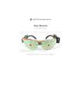
1
OLIMEXINO-85 Arduino-compatible board USER’S MANUAL Document revision D, July 2015 Designed by OLIMEX Ltd, 2013 All boards produced by Olimex LTD are ROHS compliant OLIMEX© 2015 OLIMEXINO-85 user's manual DISCLAIMER © 2015 Olimex Ltd. Olimex®, logo and combinations thereof, are registered trademarks of Olimex Ltd. Other product names may be trademarks of others and the rights belong to their respective owners. The information in this document is provided in connection with Olimex products. No license, express or implied or otherwise, to any intellectual property right is granted by this document or in connection with the sale of Olimex products. This work is licensed under the Creative Commons Attribution-ShareAlike 3.0 Unported License. To view a copy of this license, visit http://www.creativecommons.org/licenses/by-sa/3.0/. This hardware design by Olimex LTD is licensed under a Creative Commons Attribution-ShareAlike 3.0 Unported License. The software developed by Olimex LTD is released under GPL. The software developed by Micronucleus, Little Wire and Digispark is released under their respective licenses. It is possible that the pictures in this manual differ from the latest revision of the board. The product described in this document is subject to continuous development and improvements. All particulars of the product and its use contained in this document are given by OLIMEX in good faith. However all warranties implied or expressed including but not limited to implied warranties of merchantability or fitness for purpose are excluded. This document is intended only to assist the reader in the use of the product. OLIMEX Ltd. shall not be liable for any loss or damage arising from the use of any information in this document or any error or omission in such information or any incorrect use of the product. This evaluation board/kit is intended for use for engineering development, demonstration, or evaluation purposes only and is not considered by OLIMEX to be a finished end-product fit for general consumer use. Persons handling the product must have electronics training and observe good engineering practice standards. As such, the goods being provided are not intended to be complete in terms of required design-, marketing-, and/or manufacturing-related protective considerations, including product safety and environmental measures typically found in end products that incorporate such semiconductor components or circuit boards. Olimex currently deals with a variety of customers for products, and therefore our arrangement with the user is not exclusive. Olimex assumes no liability for applications assistance, customer product design, software performance, or infringement of patents or services described herein. THERE IS NO WARRANTY FOR THE DESIGN MATERIALS AND THE COMPONENTS USED TO CREATE OLIMEXINO-85. THEY ARE CONSIDERED SUITABLE ONLY FOR OLIMEXINO-85. THE HARDWARE DESIGN OF OLIMEXINO-85 IS INFLUENCED HEAVILY BY THE ORIGINAL DESIGNS OF LITTLE WIRE PROJECT AND DIGISTUMP'S DIGIPARK BOARD. THE HARDWARE DESIGN IS ALSO INSPIRED BY ALL OTHER ATTINY85 BOOTLOADER PROJECTS RELEASED PREVIOUSLY. THE FIRMWARE USES THE VID/PID COUPLE DONATED BY DIGISTUMP TO THE COMMUNITY. OLIMEXINO-85 WOULD NOT HAVE BEEN POSSIBLE WITHOUT THE EXISTENCE OF MICRONUCLEUS AND DIGISPARK PROJECTS. Page 2 of 23 OLIMEX© 2015 OLIMEXINO-85 user's manual Table of Contents DISCLAIMER............................................................................................................. 2 CHAPTER 1: OVERVIEW........................................................................................5 1. Introduction to the chapter.......................................................................................................5 1.1 Features.....................................................................................................................................5 1.2 Target market and purpose of the board...............................................................................5 1.3 Board variants..........................................................................................................................6 1.4 Board version used in the manual..........................................................................................6 1.5 Organization.............................................................................................................................6 CHAPTER 2: SETTING UP THE OLIMEXINO-85 BOARD...............................8 2. Introduction to the chapter.......................................................................................................8 2.1 Electrostatic warning...............................................................................................................8 2.2 Requirements........................................................................................................................... 8 2.3 Powering the board..................................................................................................................9 2.4 Connecting to the Arduino IDE..............................................................................................9 2.5 Examples and libraries tested by OLIMEX..........................................................................9 2.6 Reprogramming the ATtiny85..............................................................................................10 CHAPTER 3: OLIMEXINO-85 BOARD DESCRIPTION...................................11 3. Introduction to the chapter..................................................................................................... 11 3.1 Layout (top view)................................................................................................................... 11 3.2 Layout (bottom view).............................................................................................................12 CHAPTER 4: ATMEL AVR ATTINY85................................................................. 13 4. Introduction to the chapter.....................................................................................................13 4.1 The microcontroller...............................................................................................................13 4.2 Serial programming of the microcontroller........................................................................ 14 CHAPTER 5: CONNECTORS AND PINOUT......................................................16 5. Introduction to the chapter.....................................................................................................16 5.1 USB connector........................................................................................................................16 5.2 GPIO connector..................................................................................................................... 16 5.3 Jumper description................................................................................................................17 5.4 Additional hardware components........................................................................................ 17 CHAPTER 6: SCHEMATICS..................................................................................18 6. Introduction to the chapter.....................................................................................................18 6.1 Eagle schematic......................................................................................................................18 6.2 Physical dimensions...............................................................................................................20 CHAPTER 7: REVISION HISTORY AND SUPPORT........................................ 21 7. Introduction to the chapter.....................................................................................................21 7.1 Document revision................................................................................................................. 21 7.2 Board revision........................................................................................................................ 21 Page 3 of 23 OLIMEX© 2015 OLIMEXINO-85 user's manual 7.3 Useful web links and purchase codes...................................................................................22 7.4 Product support..................................................................................................................... 23 Page 4 of 23 OLIMEX© 2015 OLIMEXINO-85 user's manual CHAPTER 1: OVERVIEW 1. Introduction to the chapter Thank you for choosing the OLIMEXINO-85 from Olimex! This document provides a user’s guide for OLIMEXINO-85. As an overview, this chapter gives the scope of this document and lists the board’s features. The document’s organization is then detailed. The OLIMEXINO-85 development board enables code development of applications running on the AVR ATtiny85 microcontroller, manufactured by Atmel Corporation, USA. OLIMEXINO-85 is an open-source, open-hardware project and all documentation is available to the customer. 1.1 Features The board has the following set of features (note about the difference between the two versions of the board): ATtiny85-PU microcontroller with pre-loaded "micronucleus tiny85" bootloader Programmed via the USB type B connector Tested and working with Digisparks's Arduino distribution Breadbord compatible via the header Two LEDs – user-programmable and power status Reset button All components already soldered (unlike the DIY version) Easy-to-replace components in case of fault Open-hardware board, board schematics and layout available for Eagle Open-software board, thanks to the Digispark's community effort and the micronucleus project • Dimensions - (1.275×0.800)'' ~ (32×20)mm • • • • • • • • • • 1.2 Target market and purpose of the board All boards in the OLIMEXINO family feature a built-in bootloader (for serial programming without special tools). The main usage of the boards is software embedded development without the urge of understanding perfectly the hardware using Arduino or Arduino-derived IDE. The strong points of the OLIMEXINO-85 are: the tiny form factor, the small consumption, the fact that you can program it without special programmer via the USB cable. Customers have full access to the technical documentation of the board. The software is released under General Purpose License and the board is considered open-hardware – all schematics and board design files are available to the customer under the Creative Commons AttributionShareAlike 3.0 Unported License. Page 5 of 23 OLIMEX© 2015 OLIMEXINO-85 user's manual 1.3 Board variants There are two major board variants named: OLIMEXINO-85-ASM and OLIMEXINO-85-KIT. The difference between the two versions is that the KIT one comes with no components soldered. The already soldered version is called ASM (short from “assembled”). It is possible that the board or the kit you own has either mini USB connector or USB type B, connector. This might alter the recommended cable. Initially, we used to mount mini USB connector since we believed most people already have some sort of mini USB cable which would reduce the end cost for the customer. However, the mini USB was much harder to place and solder than the rest of the components and many customers found it frustrating. We decided to place USB type B for newer revisions which is much easier to solder. This document is suitable for both boards. However, for more precise soldering instructions (regarding the KIT variant) it is recommended to refer to the soldering guide, which is a stand-alone document and might be downloaded from the KIT's web page. Other similar boards manufactured by Olimex: OLIMEXINO-85BC - a board similar to OLIMEXINO-85-ASM that has a battery connector and battery charger; uses mini USB connector OLIMEXINO-85S – the smallest ATTiny85 board that we manufacture - (0.665×0.500) inch, uses micro USB connector and can be powered by a battery SIMON-85 – an implementation of the SIMON game to test your memory skill SIMON-85-KIT – same as above but available as kit to solder yourself FOSDEM-85 – a kit for soldering with penguin shape, can be attached to a key chain 1.4 Board version used in the manual Hardware revision B boards and resources were used while writing this document. It is possible that they are outdated so it is always recommended to refer to the stand-alone schematics available at our web-site. The hardware revision of your OLIMEXINO-85 is printed on the top under the name of the board. 1.5 Organization Each section in this document covers a separate topic, organized as follows: – Chapter 1 is an overview of the board usage and features – Chapter 2 provides a guide for quickly setting up the board and software notes – Chapter 3 outlines the main parts of the OLIMEXINO-85 – Chapter 4 describes the component that is the heart of the board – the ATtiny85 and explains the needed connections for external programming via a compatible tool – Chapter 5 covers the connector pinout, peripherals and jumper description Page 6 of 23 OLIMEX© 2015 OLIMEXINO-85 user's manual – Chapter 6 provides the schematics and the dimensions of the board – Chapter 7 contains the revision history, useful links and support information Page 7 of 23 OLIMEX© 2015 OLIMEXINO-85 user's manual CHAPTER 2: SETTING UP THE OLIMEXINO-85 BOARD 2. Introduction to the chapter This section helps you set up the OLIMEXINO-85 development board for the first time. Please consider first the electrostatic warning to avoid damaging the board, then discover the hardware and software required to operate the board. The procedure to power up the board is given, and a description of the default board behavior is detailed. 2.1 Electrostatic warning OLIMEXINO-85 is shipped in a protective anti-static package. The board should not get exposed to high electrostatic potentials. A grounding strap or similar protective device should be worn when handling the board. Avoid touching the component pins or any other metallic element without such a strap. 2.2 Requirements In order to set up the OLIMEXINO-85 optimally one or more additional items may be used. They might be generally placed in two categories: Required – items that are needed in order to achieve minimum functionality; Recommended – items that are good to have in order to be able to interact with the most important of the features of the board; Required items: - USB type A to USB type B – to connect to a personal computer; used for powering the board and uploading new programs (note that older revisions of the board might have only USB mini connector – if that is the case you would need USB mini cable) Recommended items: - Breadboard – for solderless access to GPIO and VCC/GND pins via jumper wires - Jumper wires – wires for easier interfacing of different pins - AVR-compatible programmer – to restore the bootloader program in case you erease it - External power supply unit – 3.6V DC for stand-alone power (no mini USB) Some of the above-suggested items can be purchased from Olimex, for instance: USB-A-B-CABLE or USB-MINI-CABLE – standard cables depending on the connector BREADBOARD-1 – with 0.1' step that allows easy plugging of the OLIMEXINO-85 JUMPER-WIRES – wires with male and/or female connectors for use with breadboards AVR-ISP500 – compatible programmer with 6-pin and 10-pin ICSP connectors AVR-ISP-MK2 – compatible programmer with 10-pin ICSP connector Page 8 of 23 OLIMEX© 2015 OLIMEXINO-85 user's manual 2.3 Powering the board The usual way to power OLIMEXINO-85 would be to connect it to your computer via USB cable. The OLIMEXINO-85 has a USB type B connector (or mini USB connector, older revisions have the smaller one) mounted so make sure your cable is suitable. The other way to power OLIMEXINO-85 – supply 2.7VDC to 5VDC to the VCC pin of the header. Connect the supply's ground pin to the board's GND pin. 2.4 Connecting to the Arduino IDE The ATtiny85 microcontroller of the OLIMEXINO-85 comes pre-programmed with a bootloader firmware. This firmware allows it to act as a USB device and new software can be uploaded by via a USB cable by a modified version of the Arduino IDE. The OLIMEXINO-85 runs the “Micronucleus” bootloader, an open source community project. The project repository can be found here: https://github.com/micronucleus/micronucleus This bootloader is also used by the Digispark board – the board that inspired OLIMEXINO-85. OLIMEXINO-85 uses the VID/PID pair that the creator of the Digispark – Digistump donated to the community. For complete and latest instructions on how to use connect to Arduino IDE please visit: http://digistump.com/wiki/digispark/tutorials/connecting There are also good instructions on how to select the proper board so you can upload programs. It is important that due to the small size of OLIMEXINO-85 it has a specific set of settings and a special algorithm of uploading. OLIMEXINO-85 is recognized as the default board that is selected by default after the installation of the Digistump support in the Arduino “Board Manager”. That is “Digispark (Default – 16.5mhz)” under “Tools → Board” When you have a program ready to upload you need to disconnect the board from the mini USB! Then press the upload button in the Arduino IDE interface and you will be asked to connect the board in the next 60 seconds. After you connect the OLIMEXINO-85 don't press anything and just wait until the code is uploaded! 2.5 Examples and libraries tested by OLIMEX There are number of examples that show different applications of OLIMEXINO-85. They might be downloaded from the software section of the OLIMEXINO-85's own web-page here: https://www.olimex.com/Products/Duino/AVR/OLIMEXINO-85-ASM. Page 9 of 23 OLIMEX© 2015 OLIMEXINO-85 user's manual 2.6 Reprogramming the ATtiny85 During your work you might accidentally delete the bootloader on the microcontroller or even worse – you might burn the ATtiny85 microcontroller. In both cases you would need to download the default bootloader to ATtiny85 to be able to connect and program via the Digispark's Arduino. Since the OLIMEXINO-85 lacks the required interface you would need jumper wires or your own external socket suitable for the task. You might find a table with correct connections and operations required to do in chapter 4.2 of this user's manual. The binaries with the bootloader are found in the demo archive that might be downloaded from OLIMEXINO-85's web-page. The hex and elf sources are placed in the “OLIMEXINO85_firmware” folder. When you get the files and fix the connections you would need a tool able to upload the bootloader to the ATtiny85 target via your programmer. There are two main software environments used: 1) Use AVR/Atmel Studio or AVRDude to upload respectively the .elf or the .hex to the target ATtiny85. The .elf file contains the proper fuses and configuration bits. You have to set them manually if you use the .hex file. Extended fuse should be: 0xFE – this value enables self programming and keeps the serial programming enabled High fuse should be: 0xDD – this values sets PLL Clock; start-up time PWRDWN/RESET: 1K CK/14 CK + 64 ms Low fuse should be: 0xE1 – this values sets brown-out detection at VCC=2.7 V 2) If you use AVRDude then you need to pass the fuse settings as command line: lfuse:w:0xE1:m -U hfuse:w:0xDD:m -U efuse:w:0xFE:m Usually the command to program the board via AVRDude looks like: avrdude -c stk500v2 -P com26 -p t85 -U flash:w:Olimexino-85_ProductionTest_v_1_0_0.hex -U lfuse:w:0xE1:m -U hfuse:w:0xDD:m -U efuse:w:0xFE:m ,where stk500v2 is the programmer's interface abbreviation as per AVRdude's documentation t85 is the abriviation of the name of the target microcontroller as per AVRdude's documentation Olimexino-85_ProductionTest_v_2_0_1.hex is the name of our binary code. Page 10 of 23 OLIMEX© 2015 OLIMEXINO-85 user's manual CHAPTER 3: OLIMEXINO-85 BOARD DESCRIPTION 3. Introduction to the chapter Here you get acquainted with the main parts of the board. Note the names used on the board might differ from the names used below to describe them. For the actual names check the OLIMEXINO85-ASM board itself. 3.1 Layout (top view) The picture below shows top layout of the initial revision of OLIMEXINO-85-ASM. Page 11 of 23 OLIMEX© 2015 OLIMEXINO-85 user's manual 3.2 Layout (bottom view) The bottom of the board doesn't contain any active or passive elements. It is the place where most soldering is done and you should be careful for the surface you place the board on, to avoid accidental short-circuits. Page 12 of 23 OLIMEX© 2015 OLIMEXINO-85 user's manual CHAPTER 4: ATMEL AVR ATTINY85 4. Introduction to the chapter In this chapter is located the information about the heart of OLIMEXINO-85 – its microcontroller. The information is a modified version of the datasheet provided by its manufacturers. 4.1 The microcontroller The list of features for ATtiny85 is listed below: High Performance, Low Power AVR® 8-Bit Microcontroller Advanced RISC Architecture 120 Powerful Instructions – Most Single Clock Cycle Execution 32 x 8 General Purpose Working Registers Fully Static Operation Non-volatile Program and Data Memories 2/4/8K Bytes of In-System Programmable Program Memory Flash Endurance: 10,000 Write/Erase Cycles 128/256/512 Bytes In-System Programmable EEPROM Endurance: 100,000 Write/Erase Cycles 128/256/512 Bytes Internal SRAM Programming Lock for Self-Programming Flash Program and EEPROM Data Security Peripheral Features 8-bit Timer/Counter with Prescaler and Two PWM Channels 8-bit High Speed Timer/Counter with Separate Prescaler 2 High Frequency PWM Outputs with Separate Output Compare Registers Programmable Dead Time Generator USI – Universal Serial Interface with Start Condition Detector 10-bit ADC 4 Single Ended Channels 2 Differential ADC Channel Pairs with Programmable Gain (1x, 20x) Temperature Measurement Programmable Watchdog Timer with Separate On-chip Oscillator On-chip Analog Comparator Special Microcontroller Features debugWIRE On-chip Debug System In-System Programmable via SPI Port External and Internal Interrupt Sources Low Power Idle, ADC Noise Reduction, and Power-down Modes Enhanced Power-on Reset Circuit Programmable Brown-out Detection Circuit Internal Calibrated Oscillator I/O and Packages Six Programmable I/O Lines 8-pin PDIP, 8-pin SOIC, 20-pad QFN/MLF, and 8-pin TSSOP (only ATtiny45/V) Operating Voltage Page 13 of 23 OLIMEX© 2015 OLIMEXINO-85 user's manual 1.8 - 5.5V for ATtiny25V/45V/85V 2.7 - 5.5V for ATtiny25/45/85 Speed Grade ATtiny25V/45V/85V: 0 – 4 MHz @ 1.8 - 5.5V, 0 - 10 MHz @ 2.7 – 5.5V ATtiny25/45/85: 0 – 10 MHz @ 2.7 - 5.5V, 0 - 20 MHz @ 4.5 – 5.5V Industrial Temperature Range Low Power Consumption Active Mode: 1 MHz, 1.8V: 300 µA Power-down Mode: 0.1 µA at 1.8V More information can be found at Atmel's web site at the following web-address: http://www.atmel.com/Images/Atmel-2586-AVR-8-bit-Microcontroller-ATtiny25-ATtiny45ATtiny85_Datasheet.pdf 4.2 Serial programming of the microcontroller The table below details the proper connections needed to establish between ICSP programmer and the board's microcontroller (ATtiny85) or to the GPIO connector (e.g. you don't need to remove the microcontroller from its plastic socket, you can lead the proper signals to the GPIO connector of ATtiny85). To establish the connection below you would need at least 6 jumper wires (male-female). If you connect the ICSP programmer tool to the GPIOs ignore the “TINY85” column in the table. If you connect the ICSP programmer tool to the TINY85 directly (or via a socket) ignore the “GPIO connector name” column. Cable connection 6-pin ICSP TINY85 GPIO connector name 1 6 1 2 8 VCC 3 7 2 4 5 0 5 1 RST 6 4 GND How to determine first pin of the above connectors and interfaces – the ICSP programmer should have a mark on the connector for its first pin (or the cable leading to the connector would have a different color on the side of first pin); the TINY85 has a dot that shows which pin is the first one; the GPIO connector has the names of the pins printed on the top of the board. If your AVR programmer has only 10-pin ICSP you can convert it to 6-pin ICSP following the schematic below: Page 14 of 23 OLIMEX© 2015 OLIMEXINO-85 user's manual Page 15 of 23 OLIMEX© 2015 OLIMEXINO-85 user's manual CHAPTER 5: CONNECTORS AND PINOUT 5. Introduction to the chapter In this chapter are presented the connectors that can be found on the board all together with their pinout and notes about them. Jumpers functions are described. Notes and info on specific peripherals are presented. Notes regarding the interfaces are given. 5.1 USB connector The USB is usually used to establish connection with the Digispark Arduino IDE. The user's code is transferred to the board via the USB. Note that the connection to the IDE is possible only a few seconds after powering the OLIMEXINO-85. This is because the bootloader code that establishes the connection is active for a short period of time – after that period the board starts executing user's code. This means you would need to power down the board every-time before code upload. The data lines D- and D+ are multiplexed with signals named “3” and “4” of the GPIO connector. This means you can use 3 and 4 in your code which executes after the bootloader phase. If you have USB cable plugged GPIO pins with names “3” and “4” will not work properly. USB connector Pin # Signal name Processor pin 1 POWER - 2 D- 2 3 D+ 3 4 - - 5 GND - The connector case is also grounded. 5.2 GPIO connector The 8-pin GPIO connector is used to interface additional interfaces with the OLIMEXINO-85. You can use it to connect buttons, LEDs and additional components. You can use it to control I2C devices and more. The connector can provide power and also can be used TO POWER the OLIMEXINO-85. There are 3 GPIOs which are always available and 2 GPIOs that become available when the USB is not in use. Page 16 of 23 OLIMEX© 2015 OLIMEXINO-85 user's manual GPIO-1 connector Pin # Signal name Processor pin 1 0 5 2 1 6 3 2 7 4 3 2 5 4 3 6 #RST 1 7 GND 4 8 VCC 8 5.3 Jumper description The board has no hardware jumpers. 5.4 Additional hardware components The components below are mounted on OLIMEXINO-85 but are not discussed above. They are listed here for completeness: Reset button – used to reset the board PWR LED – green LED that turns on upon powering the board STAT LED – programmable general-purpose red LED Page 17 of 23 OLIMEX© 2015 OLIMEXINO-85 user's manual CHAPTER 6: SCHEMATICS 6. Introduction to the chapter In this chapter is located information about the schematics describing logically and physically OLIMEXINO-85. 6.1 Eagle schematic Search-able OLIMEXINO-85 schematics and sources may be found at the device's web page at our GitHub repository here: https://github.com/OLIMEX/OLIMEXINO85/tree/master/HARDWARE/OLIMEXINO-85-ASM. An image of the schematic might be found on the next manual page for quicker reference. Our design software of choice is usually Eagle by Cad Soft version 4.16r2. However, the files should be compatible with the latest Eagle available. Cad Soft offers a trial version of their software that allows you to inspect schematics and board files (without being able to modify them). This work is licensed under the Creative Commons Attribution-ShareAlike 3.0 Unported License. To view a copy of this license, visit http://creativecommons.org/licenses/by-sa/3.0/. If you are looking for a schematic of an older revision of the board and it isn't available at our web site you may request it by the support e-mail. Page 18 of 23 OLIMEX© 2015 OLIMEXINO-85 user's manual Page 19 of 23 OLIMEX© 2015 OLIMEXINO-85 user's manual 6.2 Physical dimensions Note that all dimensions are in inches. The highest element on the board is capacitor C1 with 0.5 inches of height (includes the PCB height). Page 20 of 23 OLIMEX© 2015 OLIMEXINO-85 user's manual CHAPTER 7: REVISION HISTORY AND SUPPORT 7. Introduction to the chapter In this chapter you will find the current and the previous version of the document you are reading. Also the web-page for your device is listed. Be sure to check it after a purchase for the latest available updates and examples. 7.1 Document revision Revision, date Changes Modified page A, 27.11.13 Initial manual release All B, 31.01.14 Adjusted manual to fit the changes of the USB connector Multiple C, 02.07.15 Updates regarding the bootloader used Multiple D, 07.07.15 Fixed wrongfully suggested fuse settings Multiple 7.2 Board revision Remember to check the schematics and the board design files to compare the differences. Revision Notable changes A Initial release of the board B 1 USB mini connector was changed to USB type B 2 Added RST_E jumper (in open position by default) instead of removing the RST pin from the extension. 3 R6(NA) pads are now added to the RST line just in case a resistor is needed Page 21 of 23 OLIMEX© 2015 OLIMEXINO-85 user's manual 7.3 Useful web links and purchase codes The web pages you can visit for more information about your device are: https://www.olimex.com/Products/Duino/AVR/OLIMEXINO-85-ASM/ https://www.olimex.com/Products/Duino/AVR/OLIMEXINO-85-KIT/ A place for general questions, FAQ or friendly talk: https://www.olimex.com/forum/ You may may join our IRC channel #olimex @ freenode.net (http://webchat.freenode.net/? channels=olimex) ORDER CODES: OLIMEXINO-85-ASM – the assembled version of OLIMEXINO-85 OLIMEXINO-85-KIT – the kit version of OLIMEXINO-85, you would need to first solder it together to be able to use it USB-A-B-CABLE for latest board revisions; USB-MINI-CABLE for board revision A – standard cables to attach the board to a personal computer How to purchase? You can purchase directly from our online shop or from any of our distributors. Note that usually it is faster and cheaper to purchase Olimex products from our distributors. List of confirmed Olimex LTD distributors and resellers: https://www.olimex.com/Distributors. Please visit https://www.olimex.com/ for more info. Page 22 of 23 OLIMEX© 2015 OLIMEXINO-85 user's manual 7.4 Product support For product support, hardware information and error reports mail to: [email protected]. All document or hardware feedback is welcome. Note that we are primarily a hardware company and our software support is limited. Please consider reading the paragraph below about the warranty of Olimex products. All goods are checked before they are sent out. In the unlikely event that goods are faulty, they must be returned, to OLIMEX at the address listed on your order invoice. OLIMEX will not accept goods that have clearly been used more than the amount needed to evaluate their functionality. If the goods are found to be in working condition, and the lack of functionality is a result of lack of knowledge on the customers part, no refund will be made, but the goods will be returned to the user at their expense. All returns must be authorized by an RMA Number. Email [email protected] for authorization number before shipping back any merchandise. Please include your name, phone number and order number in your email request. Returns for any unaffected development board, programmer, tools, and cables permitted within 7 days from the date of receipt of merchandise. After such time, all sales are considered final. Returns of incorrect ordered items are allowed subject to a 10% restocking fee. What is unaffected? If you hooked it to power, you affected it. To be clear, this includes items that have been soldered to, or have had their firmware changed. Because of the nature of the products we deal with (prototyping electronic tools) we cannot allow returns of items that have been programmed, powered up, or otherwise changed post shipment from our warehouse. All returned merchandise must be in its original mint and clean condition. Returns on damaged, scratched, programmed, burnt, or otherwise 'played with' merchandise will not be accepted. All returns must include all the factory accessories which come with the item. This includes any In-Circuit-Serial-Programming cables, anti-static packing, boxes, etc. With your return, enclose your PO#. Also include a brief letter of explanation of why the merchandise is being returned and state your request for either a refund or an exchange. Include the authorization number on this letter, and on the outside of the shipping box. Please note: It is your responsibility to ensure that returned goods reach us. Please use a reliable form of shipping. If we do not receive your package we will not be held liable. Shipping and handling charges are not refundable. We are not responsible for any shipping charges of merchandise being returned to us or returning working items to you. The full text might be found at https://www.olimex.com/wiki/GTC#Warranty for future reference. Page 23 of 23