1
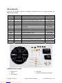
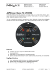
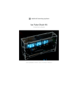
Web Site: www.parallax.com
Forums: forums.parallax.com
Sales: [email protected]
Technical: [email protected]
Office: (916) 624-8333
Fax: (916) 624-8003
Sales: (888) 512-1024
Tech Support: (888) 997-8267
AVRSimon Game Kit (#28905)
The Parallax AVRSimon Game Kit, designed by Grand Idea Studio, is a re-creation of the addictive, flyingsaucer-shaped memory game of Simon launched in 1978 by Milton Bradley. The premise of the game is
simple: Repeat the sequence of lights and tones.
This easy-to-assemble kit is perfect for learning how to solder. Additionally, all design files, including the
schematic and source code, are available for you to learn from and modify to create your own projects.
Features
y
y
y
y
Completely open-source project with all design files available
Easy-to-assemble kit
Simple design is a perfect platform for learning how to solder
Optional game play enhancements: No sound mode, fast mode, no LED mode, and reverse mode
Key Specifications
y
y
y
Power requirements: CR2032 3V Lithium coin cell battery (not included)
Interface: 6-pin male header for optional Atmel AVR reprogramming
Dimensions: Approximate PCB diameter is 3.25 in (8.5 cm)
Copyright © Parallax Inc.
Downloaded from Elcodis.com electronic components distributor
AVRSimon Game Kit (#28905)
v1.0 3/22/2010 Page 1 of 10
Bill of Materials
Verify that your AVRSimon Game Kit is complete in accordance with the list below, and gather the
additional items needed.
Designator
Quantity
R1
R5
R2
R3, R4, R6
C1
1
1
1
3
1
1
1
1
1
1
1
4
1
1
1
1
1
D3
D1
D4
D2
SW5
SW1-SW4
U1
P1
U1
BT1
LS1
Description
Part #
Resistor, 1 kΩ (brown, black, red)
Resistor, 10 kΩ (brown, black, orange)
Resistor, 3.3 kΩ (orange, orange, red)
Resistor, 330 Ω (orange, orange, brown)
Capacitor, ceramic, 0.1uF
AVRSimon PCB
LED, Green
LED, Red
LED, Yellow
LED, Blue
SPDT slide switch, 2mm
SPST pushbutton
Socket, DIP20
Header, 3 x 2 vertical, male
AVR Microcontroller, pre-programmed
Battery holder,CR2032 Lithium
Piezoelectric Buzzer
150-01020
150-01030
150-03314
150-03315
211-01011
300-28905
350-00001
350-00006
350-00007
350-00030
400-00026
400-00030
450-02020
451-00602
604-28905
753-00004
900-00017
Additional items needed
y
y
y
Soldering iron
Solder
Eye protection
Copyright © Parallax Inc.
Downloaded from Elcodis.com electronic components distributor
y
y
Wire snips
CR2032 3V Lithium coin cell battery
AVRSimon Game Kit (#28905)
v1.0 3/22/2010 Page 2 of 10
Assembly Instructions
Assembly of the AVRSimon kit should take about 15 to 30 minutes.
The recommended assembly order is as follows, starting with the lowest profile (shortest) components
and building up from there: R1-R6, C1, SW1-SW5, D1-D4, LS1, U1, BT1. For quick reference, this list is
also printed on the back of the AVRSimon circuit board.
Most of the parts are non-polarized, meaning they can be inserted into the circuit board in any
orientation and still function normally. The only exceptions are the microcontroller U1, LEDs D1-D4, and
battery holder BT1, and care must be taken to ensure these components are inserted properly to avoid
potential damage to AVRSimon.
Step 1:
Begin by inserting and soldering the resistors R1R6 and capacitor C1. After clipping the leads,
insert and solder the four pushbuttons SW1-SW4
and power switch SW5. The four pushbuttons will
“snap” into the circuit board when they are
properly pushed all the way in.
Step 2:
Next, insert and solder the four LEDs, colored red,
blue, green, and yellow, denoted by D1-D4,
respectively. LEDs are polarized and must be
inserted in the proper orientation in order for
them to work. The flat edge of the plastic LED
casing designates the cathode (sometimes a
notch is used instead) and should be lined up with
the flat side of the LED outline printed on the
circuit board.
Then, insert and solder the piezo buzzer LS1.
Orientation is not crucial, but for aesthetic
reasons you may want to place it so the logo
printed on it appears right-side up.
Copyright © Parallax Inc.
Downloaded from Elcodis.com electronic components distributor
AVRSimon Game Kit (#28905)
v1.0 3/22/2010 Page 3 of 10
Step 3:
Now, insert and solder U1’s 20-pin socket. A
handy tip is to place a piece of Scotch tape over
the socket once it has been inserted into the PCB
to prevent it from falling out when you flip the
board over to solder. This part is the trickiest for
beginners, as the pins are spaced close together,
so be careful not to create any “solder bridges”
between pins.
Once the socket is soldered into place, remove
the tape if you used any and align U1 so the
notch on its plastic packaging is facing to the left
(so pin 1 is at the lower-left corner of the socket).
Gently but firmly press U1 into the socket,
ensuring that all the pins are seated properly
within the socket and none of the leads have
accidentally bent outwards.
Step 4:
Finally, flip the circuit board over and solder the
BT1 battery holder, the only surface mount part in
the kit, onto the backside of the board. Pay close
attention to the positive (“+”) and negative (“-”)
markings on the plastic part of the holder and
align the positive side with the “+” marking on
the circuit board.
Step 5:
With the kit assembly complete, the last step is to insert the CR2032 Lithium coin cell battery into the
holder. Slide the edge of the battery towards the “+” side of the battery holder and underneath the two
gold “teeth.” Then, press firmly down on the other edge of the battery until it snaps into place within the
holder.
Copyright © Parallax Inc.
Downloaded from Elcodis.com electronic components distributor
AVRSimon Game Kit (#28905)
v1.0 3/22/2010 Page 4 of 10
How to Play
In a nutshell, AVRSimon gameplay is as follows:
y
y
y
y
Turn On
Play Game
Memorize and Repeat Pattern
Score Given When Game Over
When you first power on the game, a start-up tune will welcome you. Press any of the pushbuttons to
start playing.
The game will generate a sequence of lights/sounds that you are to repeat, first starting with a single
element. After the sequence has been presented, simply press the button(s) corresponding to the LED
that was illuminated and repeat the pattern. The sequence length will increment each time you
successfully repeat the pattern, making the game increasingly more difficult as you go. The maximum
sequence length is 255.
When your game is over, a short tune will be played, the correct LED in the sequence that you were
supposed to enter will be illuminated, and then your score will be given by a series of blinking LEDs. The
green LED corresponds to ‘hundred,’ the red LED to ‘ten,’ and the blue LED to ‘one.’ For example, if you
failed after a thirteen element sequence, the red LED will first blink once and then the blue LED will blink
three times.
AVRSimon has a few optional twists to make gameplay more fun and interesting for advanced players.
These special modes are selected by holding down one the pushbuttons SW1-SW4 while first turning on
the game (multiple pushbuttons can be held down at one time to create various combinations):
SW1: No Sound/Quiet mode
No sounds are generated while in this mode, making it perfect for gameplay while late at night, in a
library, conference session, or classroom.
SW2: Fast mode
This mode increases the speed of which the LED sequence is played by three times and reduces the
length of time allowed for you to repeat the sequence. Normally, you have five seconds to make a
decision for each move. In fast mode, you’re only allowed two.
SW3: No LED mode
No LEDs are illuminated while in this mode. You’ll have to repeat the pattern based on sound alone.
SW4: Reverse move
This mode operates like a FIFO (First In, First Out) stack in which you have to replay the sequence in
reverse order (instead of repeating the exact order that the game presents).
To revert back to game’s normal mode of operation, simply power cycle the unit.
Copyright © Parallax Inc.
Downloaded from Elcodis.com electronic components distributor
AVRSimon Game Kit (#28905)
v1.0 3/22/2010 Page 5 of 10
How it Works
Hardware
The schematic is available from the AVRsimon product page; search “28905” at www.parallax.com.
Like the original game of Simon, AVRSimon’s user interface is simple, comprising four buttons, four LEDs,
and a buzzer for playing sounds. AVRSimon runs on an Atmel ATtiny2313V, an 8-bit AVR microcontroller.
One side of each button (SW1, SW2, SW3, SW4) is connected to Port B 1, 4, 0, and 3, respectively. The
other side of the buttons are connected to ground. The internal pull-up resistor (with a value between
20 kΩ and 50 kΩ, according to the ATtiny2313V data sheet) is enabled on each of the Port B pins,
removing the need for four external resistors. The buttons are active low, so the microprocessor normally
sees a high signal (‘1’), due to the pull-up resistor, when the button isn’t being pressed. When a button is
pressed, the microprocessor sees a low signal (‘0’).
The cathodes of the four LEDs, matching the four colors of the original Simon game (D1 red, D2, blue,
D3 green, D4 yellow), are connected to Port D 0, 3, 1, and 2, respectively. A current limiting resistor (R1,
R3, R4, R2) connected to VCC is used in series with each LED to limit the amount of current allowed to
flow through the LED, which sets the brightness and prevents excessive current from damaging the LED.
Like the buttons, the LEDs are active low and set up in a current sink configuration, meaning they will
turn on when the output signal on one of the Port D pins is low (‘0’). When we want to turn an LED off,
we simply set the corresponding pin’s output value to high (‘1’). Each port pin on the ATtiny2313V can
safely sink 20 mA, which is well above what the LEDs on AVRSimon require - when the red LED is on, it
requires 1.3 mA, the green 3.0 mA, blue 0.13 mA, and yellow 3.2 mA.
One side of the piezo buzzer, LS1, is connected to ground and the other side is connected to Port B 2 via
R6, a current-limiting resistor. Instead of using the general purpose I/O function as with the button
inputs and LEDs, Port B 2 is used as its special function, Output Compare for Timer 0, which output
waveforms that will drive the piezo buzzer.
Turning the game on and off is achieved with a simple slide switch used in an SPST configuration that
connects and disconnects the battery supply from the VCC bus of the circuitry. The system is powered
with a single CR2032 3V Lithium coin cell, which is easy to obtain from any local drugstore, convenience
store, or electronics outlet. The CR2032 has a very nice current capacity for its size (20mm in diameter)
of approximately 225 mAh, although the lithium battery chemistry works best for applications requiring
very low current discharge over months or years of use. Its maximum recommended continuous
discharge is 3 mA, which is what AVRSimon draws during gameplay. When the game is not being used
and while the system is waiting for a button press to begin a new game, U1 is placed into a sleep mode
and current consumption is reduced to a scant 19.5uA. With typical gameplay of a few hours a day, a
single battery should last more than a month.
There are a few other discrete components used in this design: C1 is a standard bypass/decoupling
capacitor connected close to the VCC input of U1. R5 is a pull-up resistor connected to the active-low
/RESET line of U1 that keeps the microcontroller operating properly (e.g., not resetting) unless the pin is
intentionally pulled low, which will only be done if you take advantage of the AVR In-System
Programming (ISP) functionality. P1 is the standard 6-pin AVR ISP header. This is an optional part that is
only required if you plan on making changes to the firmware and want to reprogram U1 while it is incircuit.
Copyright © Parallax Inc.
Downloaded from Elcodis.com electronic components distributor
AVRSimon Game Kit (#28905)
v1.0 3/22/2010 Page 6 of 10
Firmware
AVRSimon combines a number of basic microcontroller
functions, such as reading switch inputs and turning LEDs
on and off, with more complicated ones, such as using sleep
modes to extend battery life and playing sounds, which
makes it a great platform to learn about microcontrollers
and embedded programming.
From the highest level view, the operation of the AVRSimon
firmware is straightforward.
Upon power-up, the hardware is initialized within the aptly
named hardware_init() function, which brings the system
into a known state. The function configures the I/O pins
(LED pins as outputs, switch pins as inputs), sets up the
timers (Timer 0 is used for tone generation and Timer 1 for
timeout counting used during gameplay), and enables the
Pin Change Interrupt.
Then, simon_config() is called, which sets the gameplay
mode based on the combination of pushbuttons SW1-SW4
held down during power-up. If no buttons are pressed
during power-up, then the game will play in the normal
mode. Other modes include no sound mode, fast mode, no
LED mode, and reverse mode, and serve as an additional
challenge for advanced users. Details of each special mode
are discussed in the How to Play section.
After all configuration is complete, we move into the core simon_game() routine. Immediately after
entering simon_game(), the system is configured to enter a low-power sleep mode and to awake on a
button press from any of the four buttons. Sleep mode is attained by calling a specific sequence of
functions/macros, which define the type of sleep mode we want to enter, configuring the interrupts, and
then going to sleep:
// prepare to go to sleep/idle mode...
set_sleep_mode(SLEEP_MODE_PWR_DOWN);
cli();
sleep_enable();
sei();
sleep_cpu(); // go to sleep here to save power
Sleep mode conserves a significant amount of power by shutting down all unused modules of the
microcontroller and only keeping the absolute essential features awake. In our selected Power-Down
Mode (SLEEP_MODE_PWR_DOWN), all clocks and oscillators are disabled, all peripheral modules are
turned off, and the only ways to awaken the device are via specific resets (external, watchdog, or brown
out), serial interface or INT0 external interrupts, or a Pin Change Interrupt generated on specific port
pins when the level changes from low to high or high to low. Fore more details of sleep mode
implementations, see http://www.nongnu.org/avr-libc/user-manual/group__avr__sleep.html.
With AVRSimon, when a button press is detected via the Pin Change Interrupt on Port B 0, 1, 3, or 4
(corresponding to SW3, SW1, SW4, SW2, respectively) the system springs to life and begins the game.
Copyright © Parallax Inc.
Downloaded from Elcodis.com electronic components distributor
AVRSimon Game Kit (#28905)
v1.0 3/22/2010 Page 7 of 10
The game itself is comprised of two core functions, simon_play_moves() and simon_read_moves():
simon_play_moves() first pulls a number
from rand(), a linear feedback shift register
used as a pseudo-random number generator
(http://en.wikipedia.org/wiki/PRNG), which
is seeded at the beginning of each game
with the current value of the Timer 1
counter and whatever pushbutton was
pushed to start the game, and limits the
result from ‘0’ to ‘3’ (corresponding to one of
the four possible LED colors on AVRSimon).
The number is then stored in U1’s internal
EEPROM (Electrically Erasable Programmable
Read-Only Memory), a non-volatile storage
container with individual byte addressing, at
the memory address equal to the current
length of the sequence. The game then
plays the entire sequence that is currently in
its EEPROM, contiguously from address 0
until the end of the sequence is reached. For
more details on EEPROM handling, see the
web address at the bottom of this page.
The
game
then
enters
the
simon_read_moves() routine, which waits
for the player to begin replaying the
sequence. For each move in the sequence,
the corresponding address of the EEPROM is
read and compared with the player’s input.
If the values do not match, then the player
must have pushed the wrong button and the
game will end via the simon_failed_input()
function. If the values do match, then the
player pushed the correct button and the
game proceeds to the next move in the
sequence. If the player successfully repeats
the entire sequence, the game jumps back
to simon_play_moves() to add another
move to the sequence and repeat the
process until the game is over.
http://www.nongnu.org/avr-libc/user-manual/group__avr__eeprom.html
Copyright © Parallax Inc.
Downloaded from Elcodis.com electronic components distributor
AVRSimon Game Kit (#28905)
v1.0 3/22/2010 Page 8 of 10
Sound
Tone generation is based on the xyloduino project:
http://www.rocketnumbernine.com/2009/03/27/xyloduino-simple-arduinopiezo-organ/
...and modified to support arrays of octaves, notes, and durations in order to create melodies. Timer 0, a
hardware peripheral internal to U1, is used as an 8-bit counter that will toggle the OC0A output pin (Port
B pin 2) from low to high or high to low when the counter value (TCNT0) matches the value programmed
into the Output Compare Register (OCR0A). The toggling of the output pin will generate a square wave
at the desired frequency that is fed into the piezo buzzer LS1.
The play_note() routine is passed the octave, note, and length of the sound. It configures the
Timer/Counter Control Register (TCCR0B) and OCR0A accordingly, waits for the sound to be played, and
then disables the counter:
if (note)
{
TCCR0B = pre[(int)octave];
// set the prescaler depending on what
octave is selected
OCR0A = note >> (octave%2); // there are two octaves for each
prescale setting, so adjust accordingly
}
delay_ms(length); // play sound for specified length
TCCR0B = 0; // turn off sound
In order to play a melody (comprising a sequence of notes stored in an array), the routine is called one
time for each note:
for (i = 0; i < STARTGAME_SND_SIZE * 4; i = i + 4)
{
// octave, note, length
play_note(pgm_read_byte(startgame_snd_p + i),
pgm_read_byte(startgame_snd_p + i + 1),
pgm_read_word(startgame_snd_p + i + 2));
delay_ms(50); // pause in between notes
}
The four sounds generated on the original Simon were based on four primary notes of a bugle, which
sound “in tune” when played in any order. AVRSimon closely mimic those notes:
http://www.waitingforfriday.com/index.php/Reverse_engineering_an_MB_Electronic_Simon_game
Tone
Tone
Tone
Tone
1:
2:
3:
4:
Blue, 392 Hz (G note)
Yellow, 330 Hz (E note)
Red, 262 Hz (C note)
Green, 196 Hz (G note)
Copyright © Parallax Inc.
Downloaded from Elcodis.com electronic components distributor
AVRSimon Game Kit (#28905)
v1.0 3/22/2010 Page 9 of 10
Development Environment
AVRSimon was developed on OS X using CrossPack for AVR:
http://www.obdev.at/products/crosspack/download-de.html
Formerly known as AVR MacPack, the package contains the core compiler, debugger, and AVR-specific
tools and integrates seamlessly with Apple’s Xcode.
In-circuit device programming was achieved using an adafruit industries USBtinyISP interface:
http://www.adafruit.com/index.php?main_page=product_info&cPath=16&products_id=46
If you choose to modify AVRSimon’s firmware, you’ll need to recompile the code and then reprogram it
into the microcontroller. To reprogram, hook up the USBtinyISP to P1 (insert and solder this optional 6pin male header onto AVRSimon if you haven’t done so already), locating pin 1 by its square pad on the
backside of the circuit board (as opposed to the other pads on the connector which are circular). Then,
open a Terminal window and go to your /firmware/ directory. Finally, run the make install command,
which launches the avrdude application twice with different parameters - once to load the compiled
binary into Flash memory and once to set the device’s configuration fuses (set in the Makefile):
1) avrdude -c usbtiny -p attiny2313 -U flash:w:main.hex:i
2) avrdude -c usbtiny -p attiny2313 -U hfuse:w:0xd1:m -U lfuse:w:0xe4:m
For more information on Atmel AVR development, see:
•
•
AVR Freaks web page: http://www.avrfreaks.net/
adafruit industries’ AVR Tutorial web page: http://www.ladyada.net/learn/avr/
Additional Resources
•
•
•
Grand Idea Studio’s AVRSimon web page: www.grandideastudio.com/portfolio/AVRSimon/
Simon (game), Wikipedia entry, http://en.wikipedia.org/wiki/Simon_(game)
U.S. Patent #4,207,087, Microcomputer controlled game (the original Simon patent):
www.google.com/patents/about?id=MAIyAAAAEBAJ&dq=4207087
Copyright © Parallax Inc.
Downloaded from Elcodis.com electronic components distributor
AVRSimon Game Kit (#28905)
v1.0 3/22/2010 Page 10 of 10