1
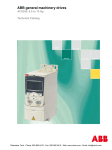
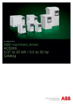
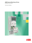
ABB standard drives
ACS310, 0.37 to 22 kW / 0.5 to 30 hp
Technical catalogue
PROFILE
INDUSTRIES
PRODUCTS
APPLICATIONS
EXPERTISE
PARTNERS
SERVICES
Clearwater Tech - Phone: 800.894.0412 - Fax: 208.368.0415 - Web: www.clrwtr.com - Email: [email protected]
Two ways to select your drive
Choice 1: Simply contact your local ABB drives
sales office (see page 17) and let them know what
you want. Use page 3 as a reference section for
more information.
Type code stucture:
1
2
3
4
5
ACS310
-
Choice 2: Build up your own ordering code using
the simple 7-step approach below. Each step is
accompanied by a reference to a page that is filled
with useful information.
03E
-
02A6
-
2
+
J400
Product series
Rating and types
Voltages
Construction
Dimension
6
Options
7
Technical data
Control connections
8
9
OR
Services
Contact and web information
Clearwater Tech - Phone: 800.894.0412 - Fax: 208.368.0415 - Web: www.clrwtr.com - Email: [email protected]
ABB standard drives
ACS310
-
03E
-
02A6
-
2
ABB standard drives
An extension to the ABB standard drives family is a
series of drives specifically designed for variable torque
applications such as pumps and fans. The specific
design includes a powerful set of features which
benefit pump and fan applications including built-in
PID controllers and PFC (pump and fan control) that
varies the drive’s performance in response to changes
in pressure, flow or other external data.
These features, combined with pre-programmed
application macros, an intuitive user interface and
several assistant screens, speed up the installation,
parameter setting and commissioning of the drive.
+
J400
Applications
■
■
■
■
Booster pumps
Submersible pumps
Irrigation pumps
Supply and return fans
Highlights
■
■
■
■
Pump and fan features
Unified height and depth
Energy efficiency calculators
Advanced or basic control panel depending on
application
■ Embedded Modbus RS-485 fieldbus interface
■ FlashDrop tool for fast parameter setting
Feature
Advantage
Benefit
Pump and fan control
(PFC) macro to control
pumps and fans in parallel
One drive controls several pumps or fans and eliminates
the need for an external programmable logic controller.
Saves cost of additional drives and external PLC.
Reduces motor stress and increases lifetime when
auxiliary motors are driven according to the needed
pump/fan capacity.
Longer life for pump or fan system while reducing
maintenance time and costs.
Interlock function enables one motor to be disengaged
from the mains supply while others continue operating
in parallel.
Maintenance can be carried out safely without stopping
process.
Soft pump and fan control
macro (SPFC)
Reduces unwanted pressure peaks in pumps and
pipelines when an auxiliary motor is started.
Reduces maintenance costs.
Longer life for pump or fan system.
Smoother processes.
Pump protection
functions
Improved protection with pre-programmed features for
preventive maintenance.
Helps avoid corrosion in the pump systems.
Reduces maintenance costs.
Longer life for pump system.
Embedded Modbus
RS-485 fieldbus interface
No need for external fieldbus options.
Integrated and compact design.
Saves costs of external fieldbus devices.
Increases reliability.
On/off cooling fan control
Cooling fan rotates only when the drive is modulating,
thereby cooling only when needed.
Silent operation.
Improves drive’s energy efficiency.
Software controlled phase
inversion
Fast and easy way to change the phase order of the
motor rotation.
Time savings as there is no need to change the output
cable order manually.
Short parameter menu
view
Only the most needed drive parameters are shown on
the drive’s parameter view. Complete parameter view
can be changed by setting one parameter.
Time savings as user can quickly see the most
important parameters.
Fast commissioning of the drive.
Energy optimizer
Improved motor efficiency with intelligent drive control
method, especially while operating on partial loads.
Boosts energy efficiency due to lower motor currents.
Reduces audible noise from the motor.
Energy efficiency tools
Several tools to illustrate saved energy (kWh), carbondioxide emissions (CO2) and cost in local currency.
Shows direct impact on energy bill and helps control
operational expenditure (OPEX).
Full output current at
50 °C ambient
Drive can be operated in ambient temperatures up to
50 °C without de-rating the output current.
Optimized drive dimensioning for wide temperature
range.
Load analyzer
Load analyzer saves process data, such as current
and torque values, which can be used to analyze the
process and dimensioning of the drive and motor.
Optimized dimensioning of the drive, motor and
process.
Clearwater Tech - Phone: 800.894.0412 - Fax: 208.368.0415 - Web: www.clrwtr.com - Email: [email protected]
Technical specification
ACS310
-
03E
-
02A6
-
2
Mains connection
Voltage and
power range
Frequency
3-phase, 200 to 240 V ± 10%
0.37 to 11 kW (0.5 to 15 hp)
3-phase, 380 to 480 V ± 10%
0.37 to 22 kW (0.5 to 30 hp)
48 to 63 Hz
Motor connection
Voltage
Frequency
Continuous loading
capability
3-phase, from 0 to Usupply
0 to 500 Hz
I2N maximum continuous output current
at ambient temperature of +40 °C.
No overloadability, derating 1% for
every additional 1 °C up to 50 °C.
ILD continuous output current at max
ambient temperature of +50 °C.
10% overloadability for one minute
every ten minutes.
Switching frequency
Default
Selectable
Acceleration time
Deceleration time
4 kHz
4 to 16 kHz with 4 kHz steps
0.1 to 1800 s
0.1 to 1800 s
Environmental limits
Ambient temperature
Altitude
Output current
Relative humidity
Degree of protection
Enclosure colour
Contamination levels
Transportation
Storage
Operation
-10 to 50 oC (14 to 122 oF), no frost
allowed
Rated current available at 0 to 1000 m
(0 to 3281 ft) reduced by 1% per 100 m
(328 ft) over 1000 to 2000 m
(3281 to 6562 ft)
Lower than 95% (without condensation)
IP20 / optional NEMA 1 enclosure
NCS 1502-Y, RAL 9002, PMS 420 C
IEC721-3-3
No conductive dust allowed
Class 1C2 (chemical gases)
Class 1S2 (solid particles)
Class 2C2 (chemical gases)
Class 2S2 (solid particles)
Class 3C2 (chemical gases)
Class 3S2 (solid particles)
Product compliance
+
J400
Programmable control connections
Two analog inputs
Voltage signal
Unipolar
Bipolar
Current signal
Unipolar
Bipolar
Resolution
Accuracy
One analog output
Auxiliary voltage
Five digital inputs
Input impedance
One relay output
Type
Maximum switching voltage
Maximum switching current
Maximum continuous
current
One digital output
Type
Maximum switching voltage
Maximum switching current
Frequency
Resolution
Accuracy
0 (2) to 10 V, Rin > 312 kΩ
-10 to 10 V, Rin > 312 kΩ
0 (4) to 20 mA, Rin = 100 Ω
-20 to 20 mA, Rin = 100 Ω
0.1%
± 1%
0 (4) to 20 mA, load < 500 Ω
24 V DC ± 10%, max. 200 mA
12 to 24 V DC with internal or external
supply, PNP and NPN, pulse train
0 to 16 kHz
2.4 kΩ
NO + NC
250 V AC/30 V DC
0.5 A/30 V DC; 5 A/230 V AC
2 A rms
Transistor output
30 V DC
100 mA/30 V DC, short circuit
protected
10 Hz to 16 kHz
1 Hz, 0.2%
Serial communication
Fieldbus
Cable
Termination
Isolation
Transfer rate
Communication type
Protocol
Modbus RS-485, embedded
Schielded twisted pair, impedance 100
to150 ohms
Trunk line, drop lines allowed
Bus interface isolated from drive
1.2 to 76.8 kbit/s
Serial, asynchronous, half duplex
Modbus
Chokes
AC input chokes
AC output chokes
External option
For reducing THD in partial loads and to
comply with EN 61000-3-2.
External option
To achieve longer motor cables
Low Voltage Directive 2006/95/EC
Machinery Directive 98/37/EC
EMC Directive 2004/108/EC
Quality assurance system ISO 9001
Environmental system ISO 14001
CE and C-Tick approvals
UL, cUL and GOST R pending
RoHS compliant
EMC
Class C3 (2nd environment unrestricted distribution) inbuilt as standard
Class C2 and C1 with external optional EMC filters
Clearwater Tech - Phone: 800.894.0412 - Fax: 208.368.0415 - Web: www.clrwtr.com - Email: [email protected]
Ratings, types, voltages and construction
ACS310
-
03E
-
02A6
-
2
+
J400
Ratings
Type code
This is the unique reference number (shown above
and in column 4, right) that clearly identifies your
drive by power rating and frame size. Once you have
selected the type code, the frame size (column 6) can
be used to determine the drive dimensions, shown on
the next page.
PN
kW
1)
ILD
A
2)
Type code
Frame
size
R0
0.55
0.75
3.9
3.5
ACS310-03X-03A9-2
R0
0.75
1.0
5.2
4.7
ACS310-03X-05A2-2
R1
1.1
1.5
7.4
6.7
ACS310-03X-07A4-2
R1
1.5
2.0
8.3
7.5
ACS310-03X-08A3-2
R1
2.2
3.0
10.8
9.8
ACS310-03X-10A8-2
R2
3.0
4.0
14.6
13.3
ACS310-03X-14A6-2
R2
4.0
5.0
19.4
17.6
ACS310-03X-19A4-2
R2
5.5
7.5
26.8
24.4
ACS310-03X-26A8-2
R3
7.5
10.0
34.1
31.0
ACS310-03X-34A1-2
R4
11.0
15.0
50.8
46.2
ACS310-03X-50A8-2
R4
3-phase supply voltage 380 - 480 V units
1.3
1.2
ACS310-03X-01A3-4
0.37
0.5
Construction
"03E" within the type code (shown above) varies
depending on the drive phase and EMC filtering.
Choose below the one you need.
03 = 3-phase
E = EMC filter connected, 50 Hz frequency
U = EMC filter disconnected, 60 Hz frequency
(In case the filter is required it can easily
be connected.)
I2N
A
3-phase supply voltage 200 - 240 V units
2.6
2.4
ACS310-03X-02A6-2
0.37
0.5
Voltages
ACS310 is available in two voltage ranges:
2 = 200 - 240 V
4 = 380 - 480 V
Insert either "2" or “4”, depending on your chosen
voltage, into the type code shown above.
PN
hp
R0
0.55
0.75
2.1
1.9
ACS310-03X-02A1-4
R0
0.75
1.0
2.6
2.4
ACS310-03X-02A6-4
R1
1.1
1.5
3.6
3.3
ACS310-03X-03A6-4
R1
1.5
2.0
4.5
4.1
ACS310-03X-04A5-4
R1
2.2
3.0
6.2
5.6
ACS310-03X-06A2-4
R1
3.0
4.0
8.0
7.3
ACS310-03X-08A0-4
R1
4.0
5.0
9.7
8.8
ACS310-03X-09A7-4
R1
5.5
7.5
13.8
12.5
ACS310-03X-13A8-4
R3
7.5
10.0
17.2
15.6
ACS310-03X-17A2-4
R3
11.0
15.0
25.4
23.1
ACS310-03X-25A4-4
R3
15.0
20.0
34.1
31
ACS310-03X-034A-1
R4
18.5
25.0
41.8
38
ACS310-03X-41A8-4
R4
22.0
30.0
48.4
44
ACS310-03X-48A4-4
R4
X within the type code stands for E or U.
1)
I2N maximum continuous output current at ambient temperature of +40 °C.
No overloadability, derating 1% for every additional 1 °C up to 50 °C.
2)
ILD continuous output current at max ambient temperature of +50 °C.
10% overloadability for one minute every ten minutes.
Clearwater Tech - Phone: 800.894.0412 - Fax: 208.368.0415 - Web: www.clrwtr.com - Email: [email protected]
Dimensions
ACS310
-
03E
-
02A6
-
2
Cabinet-mounted drives (IP20 UL open)
H1
H2
+
J400
Wall-mounted drives (NEMA 1)
H3
H4
W
H5
D
D
W
Frame
size
IP20 UL open
NEMA 1
H1 H2 H3 W
D Weight H4 H5 W
D Weight
mm mm mm mm mm
kg
mm mm mm mm
kg
R0
169 202 239
70
161
1.2
257 280
70
169
R1
169 202 239
70
161
1.2
257 280
70
169
1.6
1.6
R2
169 202 239 105 165
1.5
257 282 105 169
1.9
R3
169 202 236 169 169
2.5
260 299 169 177
3.1
R4
181 202 244 260 169
4.4
270 320 260 177
5.0
H1
H2
H3
H4
H5
W
D
= Height without fastenings and clamping plate
= Height with fastenings but without clamping plate
= Height with fastenings and clamping plate
= Height with fastenings and NEMA 1 connection box
= Height with fastenings, NEMA 1 connection box and hood
= Width
= Depth
Clearwater Tech - Phone: 800.894.0412 - Fax: 208.368.0415 - Web: www.clrwtr.com - Email: [email protected]
Options
ACS310
-
03E
-
02A6
-
2
+
J400
How to select options
The options shown in the table are available within the
ACS310 range. The control panels have an associated
4-figure option code, which is shown in the second
column. It is this code that replaces J400 in the type
code above.
Options
Protection class
Ordering
code
Description
Model
*)
NEMA 1 (R0, R1, R2)
MUL1-R1
*)
NEMA 1 (R3)
MUL1-R3
*)
NEMA 1 (R4)
MUL1-R4
J400
Assistant control panel
ACS-CP-A 2)
J404
Basic control panel
ACS-CP-C 1)
*)
Panel mounting kit
ACS/H-CP-EXT
*)
Panel holder mounting kit
OPMP-01
Extension module
*)
Relay output extension
module
MREL-01
Tools
*)
FlashDrop tool
MFDT-01
*)
DriveWindow Light 2
DriveWindow Light 2
*)
Input chokes
*)
EMC filters
*)
Output chokes
*)
Ethernet adapter
Control panel
Panel mounting kit
External options
Remote monitoring
*)
1)
2)
SREA-01
= Ordering with a separate MRP code number.
The ACS310 is compatible with ACS-CP-C basic control panel Rev M or later.
The ACS310 is compatible with ACS-CP-A assistant control panel Rev E or later.
(New panel series manufactured since 2007 with serial number XYXXRXXXX,
where year Y = 7 or greater and revision R = E, F, G, …)
Clearwater Tech - Phone: 800.894.0412 - Fax: 208.368.0415 - Web: www.clrwtr.com - Email: [email protected]
Options
Interfaces
ACS310
-
03E
-
02A6
-
2
+
J400
User interfaces
Panel cover
The purpose of the panel cover is to protect the drive's
connection surfaces.The ACS310 drive is delivered with
a panel cover as standard. In addition there are two
alternative control panels available as options.
Basic control panel
The basic control panel features a single line numeric
display. The panel can be used to control the drive,
set parameter values or copy them from one drive to
another.
Basic control panel
Panel cover
(included as standard)
Assistant control panel
Assistant control panel
The assistant control panel features a multilingual
alphanumeric display for easy drive programming.
The control panel has various assistants and an inbuilt
help function to guide the user. It includes a real
time clock, which can be used during fault logging
and in controlling the drive, such as start/stop. The
control panel can be used for copying parameters for
back up or for downloading to another drive. A large
graphical display and soft keys make it extremely easy
to navigate.
Panel mounting kits
To attach the control panel to the outside of a larger
enclosure, two panel mounting kits are available. A
simple and cost-efficient installation is possible with the
ACS/H-CP-EXT kit, while the OPMP-01 kit provides a
more user-friendly solution, including a panel platform
that enables the panel to be removed in the same way
as a drive-mounted panel. The panel mounting kits
include all hardware required, including 3 m extension
cables and installation instructions.
Panel mounting kits
Clearwater Tech - Phone: 800.894.0412 - Fax: 208.368.0415 - Web: www.clrwtr.com - Email: [email protected]
Options
Interfaces
ACS310
-
03E
-
02A6
-
2
+
J400
Machine interfaces
Removable clip for
labeling
The embedded Modbus RS-485 fieldbus brings
connectivity to major automation systems. A
single twisted pair cable avoids large amounts of
conventional cabling, thereby reducing costs and
increasing system reliability.
Panel connector
Extension module
MREL-01
ACS310 has one relay output as standard. The optional
MREL-01 module offers three additional relay outputs.
The outputs can be configured for different functions
by setting selected parameters.
Protection and installation
FlashDrop connection
EMC filter
grounding
screw
(EMC)
LEDs
Fieldbus connection
Modbus RS-485
Analog I/O
Relay output
Digital output
Digital inputs
Varistor
grounding
screw
(VAR)
NEMA 1 kit
The NEMA 1 kit includes a connection box for finger
protection, conduit tube installation, and a hood for
protection against dirt and dust.
Terminal cover
The terminal cover is for protection of the I/O
connections.
Terminal cover
(included as standard)
Clamping plates
(included as standard)
Clamping plates
The clamping plates are used for protection against
electrical disturbances. The clamping plates with the
clamps are included in the drive package as standard.
MREL-01 module
Clearwater Tech - Phone: 800.894.0412 - Fax: 208.368.0415 - Web: www.clrwtr.com - Email: [email protected]
Options
External
A separate order line and type code is required for any of these external options.
FlashDrop tool
FlashDrop is a powerful palm sized tool for fast and
easy parameter selecting and setting. It gives the
possibility to hide selected parameters to protect the
machine. Only the parameters needed in the application
are shown. The tool can copy parameters between two
drives or between a PC and a drive. All the above can
be done without a power connection to the drive – in
fact, it is not even necessary to unpack the drive.
DrivePM
DrivePM (Drive parameter manager) is a tool to create,
edit and copy parameter sets for FlashDrop. For each
parameter/group the user has a possibility to hide
it, which means that the drive user does not see the
parameter/group at all.
DrivePM requirements
■ Windows 2000/XP
■ Free serial port from a PC
FlashDrop package includes
■ FlashDrop tool
■ DrivePM software on a CD-rom
■ User’s manual in English and in pdf-format on the
CD-rom
■ Cable OPCA-02 for connection between the PC and
FlashDrop tool
■ Battery charger
SREA-01 Ethernet adapter
SREA-01 Ethernet adapter with remote monitoring
access can send process data, data logs and event
messages independently, without a PLC or a dedicated
on-site computer. It has an internal web server for
configuration and drive access.
Clearwater Tech - Phone: 800.894.0412 - Fax: 208.368.0415 - Web: www.clrwtr.com - Email: [email protected]
Options
External
A separate order line and type code is required for any of these external options.
EMC filters
EMC standards in general
The ACS310's internal EMC filter is designed to meet
category C3 requirements of EN/IEC 61800-3 standard.
External EMC filters are used to enhance the drives
electromagnetic performance in conjunction with
its internal filtering. Maximum motor cable length
depends on required electromagnetic performance,
according to the table below.
Type code
ACS310-
Frame
size
Filter
type
Cable length
with EMC filter
C1
[m]
C2
[m]
Cable length
without EMC filter
C3
[m]
C3
[m]
C4
[m]
-
3-phase supply voltage 200 - 240 V units
03X-02A6-2
R0
RFI-32
10
30
03X-03A9-2
R0
RFI-32
10
30
03X-05A2-2
R1
RFI-32
10
30
30
30
-
30
30
50
30
50
03X-07A4-2
R1
RFI-32
10
30
50
30
50
03X-08A3-2
R1
RFI-32
10
30
50
30
50
03X-10A8-2
R2
RFI-32
10
30
50
30
50
03X-14A6-2
R2
RFI-33
10
30
50
30
50
03X-19A4-2
R2
RFI-33
10
30
50
30
50
03X-26A8-2
R3
RFI-34
10
30
50
30
50
03X-34A1-2
R4
RFI-34
10
30
50
30
50
03X-50A8-2
R4
RFI-34
10
30
50
30
50
-
3-phase supply voltage 380 - 480 V units
03X-01A3-4
R0
RFI-32
30
30
03X-02A1-4
R0
RFI-32
30
30
03X-02A6-4
R1
RFI-32
50
50
30
30
-
30
30
50
30
50
03X-03A6-4
R1
RFI-32
50
50
50
30
50
03X-04A5-4
R1
RFI-32
50
50
50
30
50
03X-06A2-4
R1
RFI-32
50
50
50
30
50
03X-08A0-4
R1
RFI-32
50
50
50
30
50
03X-09A7-4
R1
RFI-32
50
50
50
30
50
03X-13A8-4
R3
RFI-33
40
40
40
30
50
03X-17A2-4
R3
RFI-33
40
40
40
30
50
03X-25A4-4
R3
RFI-33
40
40
40
30
50
03X-034A-1
R4
RFI-34
-
30
-
30
50
03X-41A8-4
R4
RFI-34
-
30
-
30
50
03X-48A4-4
R4
RFI-34
-
30
-
30
50
EN 61800-3
(2004),
product
standard
EN 55011, product
family standard for
industrial, scientific
and medical (ISM)
equipment
EN 61800-3/A11 (2000),
product standard
Category C1
Group 1
Class B
1st environment,
unrestricted distribution
Category C2
Group 1
Class A
1st environment, restricted
distribution
Category C3
Group 2
Class A
2nd environment,
unrestricted distribution
Category C4
Not applicable
2nd environment, restricted
distribution
Clearwater Tech - Phone: 800.894.0412 - Fax: 208.368.0415 - Web: www.clrwtr.com - Email: [email protected]
Options
Software tools
A separate order line and type code is required for any of these software tool options.
DriveWindow Light 2
DriveWindow Light 2 is an easy-to-use start-up and
maintenance tool for ACS310 drives. It can be used
in an offline mode, which enables parameter setting
at the office even before going to the actual site.
The parameter browser enables viewing, editing and
saving of parameters. The parameter comparison
feature makes it possible to compare parameter values
between the drive and saved parameter files. With the
parameter subset you can create your own parameter
sets. Controlling the drive is one of the features in
DriveWindow Light. With this software tool, you can
monitor up to four signals simultaneously. This can
be done in both graphical and numerical format.
Any signal can be set to stop the monitoring from a
predefined level.
Start-up wizards
Start-up wizards make the setting of parameters easy.
Simply launch the wizard, select an appropriate
assistant e.g. for setting analog outputs, and all
parameters related to this function are shown together
with help pictures.
Highlights
■ Editing, saving and downloading parameters
■ Graphical and numerical signal monitoring
■ Drive control
■ Start-up wizards
DriveWindow Light requirements
■ Windows NT/2000/XP
■ Free serial port from a PC
■ Free control panel connector
Clearwater Tech - Phone: 800.894.0412 - Fax: 208.368.0415 - Web: www.clrwtr.com - Email: [email protected]
Technical data
Cooling
Fuses
ACS310 is fitted with cooling fans as standard. The
cooling air must be free from corrosive substances and
must not be above the maximum ambient temperature
of 50 oC. For more specific limits see the Technical
specification - Environmental limits in this catalogue.
Standard fuses can be used with ABB standard drives.
For input fuse connections see table below.
Cooling air flow
Selection table
Frame
size
Type code
Heat dissipation
w
3-phase supply voltage 200 - 240 V units
ACS310-03X-02A6-2
R0
42
ACS310-03X-03A9-2
R0
54
ACS310-03X-05A2-2
R1
64
Air flow
3
3
BTU/Hr
m /h
142
183
-*
)
-*
)
-*
)
-*
220
24
14
ft /min
)
Type code
Frame
size
IEC Fuses
A
Fuse
)
type*
3-phase supply voltage 200 - 240 V units
ACS310-03X-02A6-2
R0
10
gG
ACS310-03X-03A9-2
R0
10
gG
ACS310-03X-05A2-2
R1
10
gG
ACS310-03X-07A4-2
R1
16
gG
UL Fuses
A
Fuse
)
type*
10
UL class T
10
UL class T
15
UL class T
15
UL class T
ACS310-03X-07A4-2
R1
86
295
24
14
ACS310-03X-08A3-2
R1
88
302
21
12
ACS310-03X-08A3-2
R1
16
gG
15
UL class T
ACS310-03X-10A8-2
R2
111
377
21
12
ACS310-03X-10A8-2
R2
16
gG
20
UL class T
ACS310-03X-14A6-2
R2
140
476
52
31
ACS310-03X-14A6-2
R2
25
gG
30
UL class T
ACS310-03X-19A4-2
R2
180
613
52
31
ACS310-03X-19A4-2
R2
25
gG
35
UL class T
ACS310-03X-26A8-2
R3
285
975
71
42
ACS310-03X-26A8-2
R3
63
gG
60
UL class T
ACS310-03X-34A1-2
R4
328
1119
96
57
ACS310-03X-34A1-2
R4
80
gG
80
UL class T
ACS310-03X-50A8-2
R4
488
1666
96
57
ACS310-03X-50A8-2
R4
100
gG
100
UL class T
121
)
-*
)
-*
10
UL class T
138
)
-*
)
-*
10
UL class T
170
13
8
10
UL class T
10
UL class T
3-phase supply voltage 380 - 480 V units
ACS310-03X-01A3-4
R0
35
ACS310-03X-02A1-4
R0
40
ACS310-03X-02A6-4
R1
50
3-phase supply voltage 380 - 480 V units
ACS310-03X-01A3-4
R0
10
gG
ACS310-03X-02A1-4
R0
10
gG
ACS310-03X-02A6-4
R1
10
gG
ACS310-03X-03A6-4
R1
10
gG
ACS310-03X-03A6-4
R1
60
204
13
8
ACS310-03X-04A5-4
R1
69
235
13
8
ACS310-03X-04A5-4
R1
16
gG
15
UL class T
ACS310-03X-06A2-4
R1
90
306
19
11
ACS310-03X-06A2-4
R1
16
gG
15
UL class T
ACS310-03X-08A0-4
R1
107
364
24
14
ACS310-03X-08A0-4
R1
16
gG
20
UL class T
ACS310-03X-09A7-4
R1
127
433
24
14
ACS310-03X-09A7-4
R1
20
gG
25
UL class T
ACS310-03X-13A8-4
R3
161
551
52
31
ACS310-03X-13A8-4
R3
25
gG
30
UL class T
ACS310-03X-17A2-4
R3
204
697
52
31
ACS310-03X-17A2-4
R3
35
gG
35
UL class T
ACS310-03X-25A4-4
R3
301
1029
71
42
ACS310-03X-25A4-4
R3
50
gG
50
UL class T
ACS310-03X-034A-1
R4
408
1393
96
57
ACS310-03X-034A-1
R4
80
gG
80
UL class T
ACS310-03X-41A8-4
R4
498
1700
96
57
ACS310-03X-41A8-4
R4
100
gG
100
UL class T
ACS310-03X-48A4-4
R4
588
2007
96
57
ACS310-03X-48A4-4
R4
100
gG
100
UL class T
X within the type code stands for E or U.
*) Frame size R0 with free convection cooling.
X within the type code stands for E or U.
*) According to IEC-60269 standard.
Free space requirements
Enclosure
type
Space above
mm
Space below
mm
Space on left/right
mm
All frame sizes
75
75
0
Clearwater Tech - Phone: 800.894.0412 - Fax: 208.368.0415 - Web: www.clrwtr.com - Email: [email protected]
Control connections
The diagram below gives an overview of ACS310
control connections. Please refer to the ACS310 User's
Manual for more detailed information.
1
SCR
Analog input 1
0 to 10 V
2
AI1
3
GND
Reference voltage
+10 V DC, max 10 mA
4
+10 V
Analog input 2
5
AI2
6
GND
9
+24 V
10
GND
11
DCOM
12
DI1
13
DI2
Aux. voltage output
+24 V DC, max. 200 mA
PROGRAMMABLE
DIGITAL INPUTS
DI5 can also be used
as a frequency input
Modbus RTU
(RS-485)
mA
V
14
DI3
15
DI4
16
DI5
23
SHIELD
24
B J701
25
A
26
GND_A
FlashDrop
3-phase power supply,
200 to 480 V AC
S1
AI1
AI2
Screen
8
Control panel
(RJ-45)
Modbus RTU
(RS-232)
GND
PROGRAMMABLE RELAY
AND DIGITAL OUTPUTS
ROCOM
Relay output
250 V AC / 30 V DC / 6 A
RONC
RONO
DOSRC
Digital/frequency output,
PNP transistor type
30 V DC, max. 100 mA
DOOUT
DOGND
6 Output relay
module MREL-01
EMC
EMC filter grounding screw
VAR
Varistor grounding screw
L1
U1
U2
L2
V1
V2
L3
W1
W2
DI configuration
NPN connected (sink)
Analog output
0 to 20 mA
AO
AC motor
DI configuration
PNP connected (source) with external power supply
+ 24 V
ramp
pair sel.
const.
speed 1
fwd/
rev
start/
stop
9
10
11
12
13
14
15
16
+24 V
GND
DCOM
DI1
DI2
DI3
DI4
DI5
const.
speed 1
fwd/
rev
start/
stop
9
10
11
12
13
14
15
16
+24 V
GND
DCOM
DI1
DI2
DI3
DI4
DI5
0V
Clearwater Tech - Phone: 800.894.0412 - Fax: 208.368.0415 - Web: www.clrwtr.com - Email: [email protected]
Services
The services offered for ABB low voltage drives span
the entire value chain, from the moment a customer
makes the first enquiry through to disposal and
recycling of the drive. Throughout the value chain,
ABB provides training and learning, technical support
and contracts. All of this is supported by one of the
most extensive global drive sales and service networks.
All industries face a common goal: to maximize their
production output at the lowest possible cost, while
maintaining the highest quality end products. One of
ABB’s key objectives is to maximize the uptime of its
customers’ processes by ensuring optimum lifetime of
all ABB products in a predictable, safe and low cost
manner.
Order
and
delivery
Pre-purchase
Installation
and
commissioning
Operation
and
maintenance
Upgrade
and
retrofit
Replacement
and
recycling
Training and learning
Technical support
Contracts
Complete lifecycle management maximizes return on investment
helps the customer when deciding about upgrades,
retrofits and replacements.
At the heart of ABB’s services is its drive lifecycle
management model. All services available for ABB low
voltage drives are planned according to this model. For
customers it is easy to see which services are available
at which product lifecyle phase.
Professional management of the drive’s lifecycle
maximizes the return on any investment in ABB low
voltage drives.
Drive specific maintenance schedules are also based
on this four-phase model. Thus, a customer knows
precisely the timing of the part replacements plus all
other maintenance related actions. The model also
More detailed information on services can be found in
the brochure “ABB drives - Lifecycle services for low
voltage drives.”
ABB drive lifecycle management model
Drive lifecycle phases:
Active
■
The drive, with complete
lifecycle services, is available
for purchase.
Classic
■
The drive, with complete
lifecycle services, is available
for plant extensions.
Complete lifecycle services
Limited
■
Spare parts, maintenance and
repair services are available
as long as materials can be
obtained.
Obsolete
■
ABB cannot guarantee
availability of lifecycle services
for technical reasons or within
reasonable cost.
Limited lifecycle services
ABB follows a four-phase model for managing drive lifecycles, which brings enhanced customer support and improved efficiency.
Examples of lifecycle services are: selection and dimensioning, installation and commissioning, preventive and corrective maintenance,
remote services, spare part services, training and learning, technical support, upgrade and retrofit, replacement and recycling.
Clearwater Tech - Phone: 800.894.0412 - Fax: 208.368.0415 - Web: www.clrwtr.com - Email: [email protected]