1
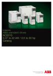
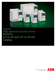
Catalog
ABB standard drives
ACS310, 0.37 to 22 kW / 0.5 to 30 hp
Two ways to select your drive
Choice 1: Simply contact your local ABB drives sales office (see page 17) and let them know what you want. Use page 3 as a reference section for
more information.
Type code stucture:
1
2
3
4
5
6
7
8
9
2
OR
ACS310
-
Choice 2: Build up your own ordering code using the simple 7-step approach below. Each step is accompanied by a reference to a page that is filled with useful information.
03E
-
02A6
-
2
+
J400
Product series
Rating and types
Voltages
Construction
Dimension
Options
Technical data
Control connections
Services
Contact and web information
3AUA0000051082 REV B EN 5.6.2009
ABB
Contents
ABB standard drives, ACS310
ABB standard drives........................................................4
Features..............................................................5
Technical specification.....................................................6
Ratings, types, voltages and construction ......................7
Type code . .........................................................7
Voltages .............................................................7
Construction........................................................7
Dimensions......................................................................8
Cabinet-mounted drives .....................................8
Wall-mounted drives ...........................................8
Options...........................................................................8
How to select options . .......................................8
User interfaces ...................................................9
Machine interfaces ...........................................10
Extension module..............................................10
Protection and installation . ...............................10
FlashDrop tool ..................................................11
SREA-01 Ethernet adapter ...............................11
EMC filters.........................................................12
Low leakage current filters.................................12
DriveWindow Light 2 ........................................13
Technical data ..............................................................14
Cooling and fuses . ...........................................14
Control connections .....................................................15
Connection examples .......................................15
Services........................................................................16
www.abb.com/drives.....................................................17
ABB
1
2
3
4
5
6
7
8
9
3AUA0000051082 REV B EN 5.6.2009
3
ABB standard drives
ACS310
-
03E
-
02A6
-
2
ABB standard drives
The ABB standard drives family has been extended with a
new series dedicated drives designed for squared torque
applications such as booster pumps and centrifugal fans.
The drive design includes a powerful set of features
which benefit pump and fan applications including builtin PID controllers and PFC (pump and fan control) that
varies the drive’s performance in response to changes
in pressure, flow or other external data. The drives also
have pre-programmed protection functions such as pipe
cleaning for preventive maintenance.
These features, combined with preprogrammed
application macros, an intuitive user interface and several
assistant screens, speed up the installation, parameter
setting and commissioning of the drive.
4
3AUA0000051082 REV B EN 5.6.2009
+
J400
Applications
■■Booster pumps
■■Submersible pumps
■■Irrigation pumps
■■Centrifugal fans
Highlights
■■Pump and fan features such and pum and fan
control (PFC and SPFC)
■■Pipe cleaning and fill functions
■■Unified hight and depth
■■Energy efficiency counters
■■Energy optimizer
■■Load Analyzer for optimized dimensioning of the
drive, motor and process
■■Embedded Modbus RS-485 fieldbus interface
■■FlashDrop tool for fast parameter setting
ABB
ABB standard drives
ACS310
-
03E
-
02A6
-
2
+
J400
Feature
Advantage
Pump and fan control (PFC)
feature to control pumps
and fans in parallel
One drive controls several pumps or fans and eliminates the Saves cost of additional drives and external PLC.
need for an external programmable logic controller.
Reduces motor stress and increases lifetime when auxiliary
motors are driven according to the needed pump/fan
capacity.
Interlock function enables one motor to be disengaged
from the mains supply while others continue operating in
parallel.
Benefit
Longer life for pump or fan system while reducing
maintenance time and costs.
Maintenance can be carried out safely without stopping
process.
Soft pump and fan control
feature (SPFC)
Reduces unwanted pressure peaks in pumps and pipelines
when an auxiliary motor is started.
Reduces maintenance costs.
Longer life for pump or fan system.
Smoother processes.
Pump protection functions
Integrated protection and control with pre-programmed
features like pipe cleaning, pipefill, inlet/outlet pressure
supervision and detection of under or over load for
preventive maintenance.
Reduces maintenance costs.
Longer life and reliable operation of pump system.
Improves process control and system reliability. Integrates
system protection.
Smoother processes: improved and optimized system.
Longer life for pump and fan system, reduced maintenance
costs.
PID controllers
Varies the drive’s performance according to the need of the
application.
Enhances production output, stability and accuracy.
Embedded Modbus
RS-485 fieldbus interface
No need for external fieldbus options.
Integrated and compact design.
Saves costs of external fieldbus devices.
Increases reliability.
On/off cooling fan control
Cooling fan rotates only when the drive is running, thereby
cooling only when needed.
Silent operation.
Improves drive’s energy efficiency.
Software controlled phase
inversion
Fast and easy way to change the phase order of the motor
rotation.
Time savings as there is no need to change the output cable
order manually.
Short parameter menu view
Only the most needed drive parameters are shown on the
drive’s parameter view. Complete parameter view can be
changed by setting one parameter.
Time savings as user can quickly see the most important
parameters.
Fast commissioning of the drive.
Energy optimizer
Improved motor efficiency with intelligent drive control
method, especially while operating on partial centrifugal
loads.
Boosts energy efficiency due to lower motor currents.
Reduces audible noise from the motor.
Energy efficiency counters
Several counters to illustrate saved energy (kWh), carbondioxide emissions (CO2) and cost in local currency.
Shows direct impact on energy bill and helps control
operational expenditure (OPEX).
Full output current at
50 °C ambient
Drive can be operated in ambient temperatures up to
50 °C without de-rating the output current.
Optimized drive dimensioning for wide temperature range.
Load analyzer
Load analyzer saves process data, such as current and
torque values, which can be used to analyze the process
and dimensioning of the drive and motor.
Optimized dimensioning of the drive, motor and process.
Compact size and high
power density ratio
Efficient cabinet space usage.
Space savings.
Unified height and depth
Optimum installation layout.
Space savings.
Different mounting options;
screw or DIN rail mounting,
sideways or side-by-side
Flexible installation.
One drive can be used in various designs, saving installation
costs and time.
User interfaces
Assistant control panel with clear alphanumerical dynamic
menus, real time clock and 14 languages.
Basic panel with numerical display.
Different control panels available according to functionality
need.
Maintenance assistant
Monitors consumed energy (kWh), running hours or motor
rotation.
Assists in preventive maintenance of the drive, motor or run
application.
Commissioning assistants
Easy set up of parameters for PID controllers, real-time
clock, serial communication, drive optimizer and drive
start-up.
Time savings with reduced need to set the parameters
manually.
Ensures all required parameters are set.
Drive protection
Motor output and I/O protected against wiring faults.
Protection against unstable supply networks.
Coated boards as standard.
Latest solution to protect the drive and offer trouble free use
and the highest quality.
ABB
3AUA0000051082 REV B EN 5.6.2009
5
Technical specification
ACS310
-
03E
-
02A6
-
2
Mains connection
Voltage and
power range
Frequency
3-phase, 200 to 240 V ± 10%
0.37 to 11 kW (0.5 to 15 hp)
3-phase, 380 to 480 V ± 10%
0.37 to 22 kW (0.5 to 30 hp)
48 to 63 Hz
Motor connection
Voltage
Frequency
Continuous loading
capability
3-phase, from 0 to Usupply
0 to 500 Hz
I2N maximum continuous output current
at ambient temperature of +40 °C.
No overloadability, derating 1% for
every additional 1 °C up to 50 °C.
ILD continuous output current at max
ambient temperature of +50 °C.
10% overloadability for one minute
every ten minutes.
Switching frequency
Default
Selectable
Acceleration time
Deceleration time
4 kHz
4 to 16 kHz with 4 kHz steps
0.1 to 1800 s
0.1 to 1800 s
Environmental limits
Ambient temperature
Altitude
Output current
Relative humidity
Degree of protection
Enclosure colour
Contamination levels
Transportation
Storage
Operation
-10 to 50 oC (14 to 122 oF), no frost
allowed
Rated current available at 0 to 1000 m
(0 to 3281 ft) reduced by 1% per 100 m (328 ft) over 1000 to 2000 m
(3281 to 6562 ft)
Lower than 95% (without condensation)
IP20 / optional NEMA 1 enclosure
NCS 1502-Y, RAL 9002, PMS 420 C
IEC721-3-3
No conductive dust allowed
Class 1C2 (chemical gases)
Class 1S2 (solid particles)
Class 2C2 (chemical gases)
Class 2S2 (solid particles)
Class 3C2 (chemical gases)
Class 3S2 (solid particles)
Product compliance
+
J400
Programmable control connections
Two analog inputs
Voltage signal
Unipolar
Bipolar
Current signal
Unipolar
Bipolar
Resolution
Accuracy
One analog output
Auxiliary voltage
Five digital inputs
Input impedance
One relay output
Type
Maximum switching voltage
Maximum switching current
Maximum continuous
current
One digital output
Type
Maximum switching voltage
Maximum switching current
Frequency
Resolution
Accuracy
0 (2) to 10 V, Rin > 312 kΩ
-10 to 10 V, Rin > 312 kΩ
0 (4) to 20 mA, Rin = 100 Ω
-20 to 20 mA, Rin = 100 Ω
0.1%
± 1%
0 (4) to 20 mA, load < 500 Ω
24 V DC ± 10%, max. 200 mA
12 to 24 V DC with internal or external
supply, PNP and NPN, pulse train
0 to 16 kHz
2.4 kΩ
NO + NC
250 V AC/30 V DC
0.5 A/30 V DC; 5 A/230 V AC
2 A rms
Transistor output
30 V DC
100 mA/30 V DC, short circuit
10 Hz to 16 kHz
1 Hz
0.2%
Serial communication
Fieldbus
Cable
Termination
Isolation
Transfer rate
Communication type
Protocol
Modbus RS-485, embedded
Schielded twisted pair, impedance 100
to150 ohms
Daisy-chained bus, without dropout lines
Bus interface isolated from drive
1.2 to 76.8 kbit/s
Serial, asynchronous, half duplex
Modbus
Chokes
AC input chokes
AC output chokes
External option
For reducing THD in partial loads and to
comply with EN/IEC 61000-3-12
External option
To achieve longer motor cables
Low Voltage Directive 2006/95/EC
Machinery Directive 98/37/EC
EMC Directive 2004/108/EC
Quality assurance system ISO 9001
Environmental system ISO 14001
CE and C-Tick approvals
UL, cUL and GOST R
RoHS compliant
EMC
Class C3 (2nd environment unrestricted distribution) inbuilt as standard
Class C2 and C1 with external optional EMC filters
6
3AUA0000051082 REV B EN 5.6.2009
ABB
Ratings, types, voltages and construction
ACS310
-
03E
-
02A6
-
2
+
J400
Type code
This is the unique reference number (shown above
and in column 4, right) that clearly identifies your
drive by power rating and frame size. Once you have
selected the type code, the frame size (column 6) can
be used to determine the drive dimensions, shown on
the next page.
Ratings
PN
kW
ABB
1)
ILD
A
2)
Type code
Frame
size
R0
0.55
0.75
3.9
3.5
ACS310-03X-03A9-2
R0
0.75
1.0
5.2
4.7
ACS310-03X-05A2-2
R1
1.1
1.5
7.4
6.7
ACS310-03X-07A4-2
R1
1.5
2.0
8.3
7.5
ACS310-03X-08A3-2
R1
2.2
3.0
10.8
9.8
ACS310-03X-10A8-2
R2
3.0
4.0
14.6
13.3
ACS310-03X-14A6-2
R2
4.0
5.0
19.4
17.6
ACS310-03X-19A4-2
R2
5.5
7.5
26.8
24.4
ACS310-03X-26A8-2
R3
7.5
10.0
34.1
31.0
ACS310-03X-34A1-2
R4
11.0
15.0
50.8
46.2
ACS310-03X-50A8-2
R4
3-phase supply voltage 380 - 480 V units
1.3
1.2
ACS310-03X-01A3-4
0.37
0.5
R0
Construction
"03E" within the type code (shown above) varies
depending on the drive phase and EMC filtering.
Choose below the one you need.
03 =3-phase
E =EMC filter connected, 50 Hz frequency
U =EMC filter disconnected, 60 Hz frequency
(In case the filter is required it can easily
be connected.)
I2N
A
3-phase supply voltage 200 - 240 V units
2.6
2.4
ACS310-03X-02A6-2
0.37
0.5
Voltages
ACS310 is available in two voltage ranges:
2 = 200 - 240 V
4 = 380 - 480 V
Insert either "2" or “4”, depending on your chosen
voltage, into the type code shown above.
PN
hp
0.55
0.75
2.1
1.9
ACS310-03X-02A1-4
R0
0.75
1.0
2.6
2.4
ACS310-03X-02A6-4
R1
1.1
1.5
3.6
3.3
ACS310-03X-03A6-4
R1
1.5
2.0
4.5
4.1
ACS310-03X-04A5-4
R1
2.2
3.0
6.2
5.6
ACS310-03X-06A2-4
R1
3.0
4.0
8.0
7.3
ACS310-03X-08A0-4
R1
4.0
5.0
9.7
8.8
ACS310-03X-09A7-4
R1
5.5
7.5
13.8
12.5
ACS310-03X-13A8-4
R3
7.5
10.0
17.2
15.6
ACS310-03X-17A2-4
R3
11.0
15.0
25.4
23.1
ACS310-03X-25A4-4
R3
15.0
20.0
34.1
31
ACS310-03X-34A1-4
R4
18.5
25.0
41.8
38
ACS310-03X-41A8-4
R4
22.0
30.0
48.4
44
ACS310-03X-48A4-4
R4
X within the type code stands for E or U.
1)
I2N maximum continuous output current at ambient temperature of +40 °C.
No overloadability, derating 1% for every additional 1 °C up to 50 °C.
2)
ILD continuous output current at max ambient temperature of +50 °C.
10% overloadability for one minute every ten minutes.
3AUA0000051082 REV B EN 5.6.2009
7
Dimensions
ACS310
-
03E
-
02A6
-
2
+
Cabinet-mounted drives (IP20 UL open)
H1
H2
Wall-mounted drives (NEMA 1)
H3
H4
H5
W
D
Frame
size
J400
D
IP20 UL open
W
NEMA 1
H1 H2 H3 W
D Weight H4 H5 W
D Weight
mm mm mm mm mm
kg
mm mm mm mm
kg
R0
169 202 239
70
161
1.1
257 280
70
169
1.5
R1
169 202 239
70
161
1.3
257 280
70
169
1.7
R2
169 202 239 105 165
1.5
257 282 105 169
1.9
R3
169 202 236 169 169
2.9
260 299 169 177
3.5
R4
181 202 244 260 169
4.4
270 320 260 177
5.0
-
02A6
2
H1= Height without fastenings and clamping plate
H2= Height with fastenings but without clamping plate
H3= Height with fastenings and clamping plate
H4= Height with fastenings and NEMA 1 connection box
H5= Height with fastenings, NEMA 1 connection box and hood
W = Width
D = Depth
Options
ACS310
-
03E
-
+
J400
How to select options
The options shown in the table are available within the
ACS310 range. The control panels have an associated
4-figure option code, which is shown in the second
column. It is this code that replaces J400 in the type
code above.
Options
Protection class
Ordering code
*)
*)
*)
Control panel
Panel mounting kit
J400
J404
*)
*)
Extension module
*)
Tools
*)
*)
External options
*)
*)
*)
Remote monitoring
8
*)
3AUA0000051082 REV B EN 5.6.2009
Description
NEMA 1 (R0, R1, R2)
NEMA 1 (R3)
NEMA 1 (R4)
Assistant control panel
Basic control panel
Panel mounting kit
Panel holder mounting kit
Relay output extension
module
FlashDrop tool
DriveWindow Light 2
Input chokes
EMC filters
Output chokes
Ethernet adapter
Model
MUL1-R1
MUL1-R3
MUL1-R4
ACS-CP-A 2)
ACS-CP-C 1)
ACS/H-CP-EXT
OPMP-01
MREL-01
*)
MFDT-01
DriveWindow Light 2
SREA-01
1)
2)
= Ordering with a separate MRP code number.
The ACS310 is compatible with ACS-CP-C basic control panel Rev M or later.
The ACS310 is compatible with ACS-CP-A assistant control panel Rev E or later.
(New panel series manufactured since 2007 with serial number XYYWWRXXXX, where year Y = 7 or greater and revision R = E, F, G, …)
ABB
Options
Interfaces
ACS310
-
03E
-
02A6
-
2
+
J400
User interfaces
Panel cover
The purpose of the panel cover is to protect the drive's
connection surfaces.The ACS310 drive is delivered with
a panel cover as standard. In addition there are two
alternative control panels available as options.
Basic control panel
The basic control panel features a single line numeric
display. The panel can be used to control the drive,
set parameter values or copy them from one drive to
another.
Basic control panel
Panel cover
(included as standard)
Assistant control panel
Assistant control panel
The assistant control panel features a multilingual
alphanumeric display for easy drive programming.
The control panel has various assistants and an inbuilt
help function to guide the user. It includes a real
time clock, which can be used during fault logging
and in controlling the drive, such as start/stop. The
control panel can be used for copying parameters for
back up or for downloading to another drive. A large
graphical display and soft keys make it extremely easy
to navigate.
Panel mounting kits
To attach the control panel to the outside of a larger
enclosure, two panel mounting kits are available. A
simple and cost-efficient installation is possible with the
ACS/H-CP-EXT kit, while the OPMP-01 kit provides a
more user-friendly solution, including a panel platform
that enables the panel to be removed in the same way
as a drive-mounted panel. The panel mounting kits
include all hardware required, including 3 m extension
cables and installation instructions.
Panel mounting kits
ABB
3AUA0000051082 REV B EN 5.6.2009
9
Options
Interfaces
ACS310
-
03E
-
02A6
-
2
+
J400
Machine interfaces
Removable clip for
labeling
The embedded Modbus RS-485 fieldbus brings
connectivity to major automation systems. A
single twisted pair cable avoids large amounts of
conventional cabling, thereby reducing costs and
increasing system reliability.
Panel connector
MREL-01 connector
Extension module
MREL-01
ACS310 has one relay output as standard. The optional
MREL-01 module offers three additional relay outputs.
The outputs can be configured for different functions
by setting selected parameters.
Protection and installation
FlashDrop connection
EMC filter
grounding
screw
(EMC)
LEDs
Fieldbus connection
Modbus RS-485
Analog I/O
Relay output
Digital output
Digital inputs
Varistor
grounding
screw
(VAR)
NEMA 1 kit
The NEMA 1 kit includes a connection box for finger
protection, conduit tube installation, and a hood for
protection against dirt and dust.
Terminal cover
The terminal cover is for protection of the I/O
connections.
Terminal cover
(included as standard)
Clamping plates
(included as standard)
Clamping plates
The clamping plates are used for protection against
electrical disturbances. The clamping plates with the
clamps are included in the drive package as standard.
MREL-01 module
NEMA 1 kit
10
3AUA0000051082 REV B EN 5.6.2009
ABB
Options
External
A separate order line and type code is required for any of these external options.
FlashDrop tool
FlashDrop is a powerful palm sized tool for fast and
easy parameter selecting and setting. It gives the
possibility to hide selected parameters to protect the
machine. Only the parameters needed in the application
are shown. The tool can copy parameters between two
drives or between a PC and a drive. All the above can
be done without a power connection to the drive – in
fact, it is not even necessary to unpack the drive.
DrivePM
DrivePM (Drive parameter manager) is a tool to
create, edit and copy parameter sets for FlashDrop.
For each parameter/group the user has a possibility
to hide it, which means that the drive user does not
see the parameter/group at all. DrivePM version 1.2 is
compatible with ACS310 drives.
DrivePM requirements
■■Windows 2000/XP/Vista
■■Free serial port from a PC
FlashDrop package includes
■■FlashDrop tool
■■DrivePM software on a CD-rom
■■User’s manual in English and in pdf-format on the
CD-rom
■■Cable OPCA-02 for connection between the PC and
FlashDrop tool
■■Battery charger
SREA-01 Ethernet adapter
SREA-01 Ethernet adapter with remote monitoring
access can send process data, data logs and event
messages independently, without a PLC or a dedicated
on-site computer. It has an internal web server for
configuration and drive access.
ABB
3AUA0000051082 REV B EN 5.6.2009
11
Options
External
A separate order line and type code is required for any of these external options.
Low leakage current filters
EMC filters
The ACS310's internal EMC filter is designed to meet
category C3 requirements of EN/IEC 61800-3 standard.
External EMC filters are used to enhance the drives
electromagnetic performance in conjunction with
its internal filtering. Maximum motor cable length
depends on required electromagnetic performance,
according to the table below.
Type code
ACS310-
Frame
size
Filter
type
Cable length
with EMC filter
C1
[m]
C2
[m]
Cable length
without EMC filter
C3
[m]
C3
[m]
C4
[m]
-
30
30
Type code
ACS310-
Frame
size
Cable length1)
with LRFI filter
Filter type
C2
[m]
3-phase supply voltage 200 - 240 V units
03X-02A6-2
R0
RFI-32
10
30
03X-03A9-2
R0
RFI-32
10
30
03X-05A2-2
R1
RFI-32
10
30
03X-01A3-4
R0
LRFI-31
10
-
30
30
03X-02A1-4
R0
LRFI-31
10
50
30
50
03X-02A6-4
R1
LRFI-31
10
03X-07A4-2
R1
RFI-32
10
30
50
30
50
03X-03A6-4
R1
LRFI-31
10
03X-08A3-2
R1
RFI-32
10
30
50
30
50
03X-10A8-2
03X-04A5-4
R1
LRFI-31
10
R2
RFI-32
10
30
50
30
50
03X-14A6-2
03X-06A2-4
R1
LRFI-31
10
R2
RFI-33
10
30
50
30
50
03X-19A4-2
R2
RFI-33
10
30
50
30
50
03X-08A0-4
R1
LRFI-32
10
03X-26A8-2
R3
RFI-34
10
30
50
30
50
03X-09A7-4
R1
LRFI-32
10
03X-34A1-2
R4
RFI-34
10
30
50
30
50
03X-50A8-2
R4
RFI-34
10
30
50
30
50
3-phase supply voltage 380 - 480 V units
03X-01A3-4
R0
RFI-32
30
30
03X-02A1-4
R0
RFI-32
30
30
03X-02A6-4
R1
RFI-32
50
50
12
Low leakage current filters are ideal for installations
where residual current devices (RCD) are required and
leakage current needs to be below 30 mA.
Low leakage current filters, 3-phase supply voltage 400 V units
-
30
30
-
30
30
50
30
50
03X-03A6-4
R1
RFI-32
50
50
50
30
50
03X-04A5-4
R1
RFI-32
50
50
50
30
50
03X-06A2-4
R1
RFI-32
50
50
50
30
50
03X-08A0-4
R1
RFI-32
50
50
50
30
50
03X-09A7-4
R1
RFI-32
50
50
50
30
50
03X-13A8-4
R3
RFI-33
40
40
40
30
50
03X-17A2-4
R3
RFI-33
40
40
40
30
50
03X-25A4-4
R3
RFI-33
40
40
40
30
50
50
03X-34A1-4
R4
RFI-34
-
30
-
30
03X-41A8-4
R4
RFI-34
-
30
-
30
50
03X-48A4-4
R4
RFI-34
-
30
-
30
50
3AUA0000051082 REV B EN 5.6.2009
1)
Internal EMC filter must be disconnected by removing the EMC screw
from the drive.
EMC standards in general
EN 61800-3
(2004),
product
standard
EN 55011, product
family standard for
industrial, scientific
and medical (ISM)
equipment
EN 61800-3/A11 (2000),
product standard
Category C1
Group 1
Class B
1st environment,
unrestricted distribution
Category C2
Group 1
Class A
1st environment, restricted
distribution
Category C3
Group 2
Class A
2nd environment,
unrestricted distribution
Category C4
Not applicable
2nd environment, restricted
distribution
ABB
Options
Software tools
A separate order line and type code is required for any of these software tool options.
DriveWindow Light 2
DriveWindow Light 2 is an easy-to-use start-up and
maintenance tool for ACS310 drives. It can be used
in an offline mode, which enables parameter setting
at the office even before going to the actual site.
The parameter browser enables viewing, editing and
saving of parameters. The parameter comparison
feature makes it possible to compare parameter values
between the drive and saved parameter files. With the
parameter subset you can create your own parameter
sets. Controlling the drive is one of the features in
DriveWindow Light. With this software tool, you can
monitor up to four signals simultaneously. This can
be done in both graphical and numerical format.
DriveWindow Light 2 version 2.9 or later is compatible
with ACS310 drives.
Start-up wizards
Start-up wizards make the setting of parameters easy.
Simply launch the wizard, select an appropriate
assistant e.g. for setting analog outputs, and all
parameters related to this function are shown together
with help pictures.
Highlights
■■ Editing, saving and downloading parameters
■■ Graphical and numerical signal monitoring
■■ Drive control
■■ Start-up wizards
DriveWindow Light requirements
■■Windows NT/2000/XP/Vista
■■Free serial port from a PC
■■Free control panel connector
ABB
3AUA0000051082 REV B EN 5.6.2009
13
Technical data
Cooling
Fuses
ACS310 is fitted with cooling fans as standard. The
cooling air must be free from corrosive substances and
must not be above the maximum ambient temperature
of 50 oC. For more specific limits see the Technical
specification - Environmental limits in this catalogue.
Standard fuses can be used with ABB standard drives.
For input fuse connections see table below.
Cooling air flow
Selection table
Frame
size
Type code
Heat dissipation
w
3-phase supply voltage 200 - 240 V units
ACS310-03X-02A6-2
R0
42
ACS310-03X-03A9-2
R0
54
ACS310-03X-05A2-2
R1
64
Air flow
3
3
BTU/Hr
m /h
ft /min
142
183
-*
)
-*
)
-*
)
-*
220
24
14
)
Type code
Frame
size
IEC Fuses
A
Fuse
)
type*
3-phase supply voltage 200 - 240 V units
ACS310-03X-02A6-2
R0
10
gG
ACS310-03X-03A9-2
R0
10
gG
ACS310-03X-05A2-2
R1
10
gG
ACS310-03X-07A4-2
R1
16
gG
UL Fuses
A
Fuse
)
type*
10
UL class T
10
UL class T
15
UL class T
15
UL class T
ACS310-03X-07A4-2
R1
86
295
24
14
ACS310-03X-08A3-2
R1
88
302
21
12
ACS310-03X-08A3-2
R1
16
gG
15
UL class T
ACS310-03X-10A8-2
R2
111
377
21
12
ACS310-03X-10A8-2
R2
16
gG
20
UL class T
ACS310-03X-14A6-2
R2
140
476
52
31
ACS310-03X-14A6-2
R2
25
gG
30
UL class T
ACS310-03X-19A4-2
R2
180
613
52
31
ACS310-03X-19A4-2
R2
25
gG
35
UL class T
ACS310-03X-26A8-2
R3
285
975
71
42
ACS310-03X-26A8-2
R3
63
gG
60
UL class T
ACS310-03X-34A1-2
R4
328
1119
96
57
ACS310-03X-34A1-2
R4
80
gG
80
UL class T
ACS310-03X-50A8-2
R4
488
1666
96
57
ACS310-03X-50A8-2
R4
100
gG
100
UL class T
10
UL class T
10
UL class T
10
UL class T
10
UL class T
3-phase supply voltage 380 - 480 V units
ACS310-03X-01A3-4
R0
35
ACS310-03X-02A1-4
R0
40
ACS310-03X-02A6-4
R1
50
138
)
-*
)
-*
)
-*
)
-*
170
13
8
121
3-phase supply voltage 380 - 480 V units
ACS310-03X-01A3-4
R0
10
gG
ACS310-03X-02A1-4
R0
10
gG
ACS310-03X-02A6-4
R1
10
gG
ACS310-03X-03A6-4
R1
10
gG
ACS310-03X-03A6-4
R1
60
204
13
8
ACS310-03X-04A5-4
R1
69
235
13
8
ACS310-03X-04A5-4
R1
16
gG
15
UL class T
ACS310-03X-06A2-4
R1
90
306
19
11
ACS310-03X-06A2-4
R1
16
gG
15
UL class T
ACS310-03X-08A0-4
R1
107
364
24
14
ACS310-03X-08A0-4
R1
16
gG
20
UL class T
ACS310-03X-09A7-4
R1
127
433
24
14
ACS310-03X-09A7-4
R1
20
gG
25
UL class T
ACS310-03X-13A8-4
R3
161
551
52
31
ACS310-03X-13A8-4
R3
25
gG
30
UL class T
ACS310-03X-17A2-4
R3
204
697
52
31
ACS310-03X-17A2-4
R3
35
gG
35
UL class T
ACS310-03X-25A4-4
R3
301
1029
71
42
ACS310-03X-25A4-4
R3
50
gG
50
UL class T
ACS310-03X-34A1-4
R4
408
1393
96
57
ACS310-03X-34A1-4
R4
80
gG
80
UL class T
ACS310-03X-41A8-4
R4
498
1700
96
57
ACS310-03X-41A8-4
R4
100
gG
100
UL class T
ACS310-03X-48A4-4
R4
588
2007
96
57
ACS310-03X-48A4-4
R4
100
gG
100
UL class T
X within the type code stands for E or U.
*) Frame size R0 with free convection cooling.
X within the type code stands for E or U.
*) According to IEC-60269 standard.
Free space requirements
14
Enclosure
type
Space above
mm
Space below
mm
Space on left/right
mm
All frame sizes
75
75
0
3AUA0000051082 REV B EN 5.6.2009
ABB
Control connections
The diagram below gives an overview of ACS310
control connections. Please refer to the ACS310 User's
Manual for more detailed information.
1
SCR
Analog input 1
0 to 10 V
2
AI1
3
GND
Reference voltage
+10 V DC, max 10 mA
4
+10 V
Analog input 2
5
AI2
6
GND
9
+24 V
10
GND
11
DCOM
12
DI1
13
DI2
Aux. voltage output
+24 V DC, max. 200 mA
PROGRAMMABLE
DIGITAL INPUTS
DI5 can also be used
as a frequency input
Modbus RTU
(RS-485)
DI3
15
DI4
16
DI5
23
SHIELD
24
B J701
25
A
26
GND_A
Control panel
(RJ-45)
Analog output
0 to 20 mA
AO
GND
PROGRAMMABLE RELAY
AND DIGITAL OUTPUTS
ROCOM
Relay output
250 V AC / 30 V DC / 6 A
RONC
RONO
DOSRC
Digital/frequency output,
PNP transistor type
30 V DC, max. 100 mA
DOOUT
DOGND
6 Output relay
module MREL-01
EMC
EMC filter grounding screw
VAR
Varistor grounding screw
L1
U1
U2
L2
V1
V2
L3
W1
W2
DI configuration
NPN connected (sink)
AC motor
DI configuration
PNP connected (source) with external power supply
ACS310: X1
Ramp Const
Fwd /
pair sel Speed 1 Rev
mA
V
14
FlashDrop
3-phase power supply,
200 to 480 V AC
S1
AI1
AI2
Screen
8
Start /
Stop
+24 V
GND
DCOM
DI1
DI2
DI3
DI4
DI5
ACS310: X1
+ 24 V
const.
speed 1
fwd/
rev
start/
stop
9
10
11
12
13
14
15
16
+24 V
GND
DCOM
DI1
DI2
DI3
DI4
DI5
0V
ABB
3AUA0000051082 REV B EN 5.6.2009
15
Services
Pre-purchase
Order
and
delivery
Installation
and
commissioning
Operation
and
maintenance
Upgrade
and
retrofit
Replacement
and
recycling
Training and learning
Technical support
Contracts
The services offered for ABB low voltage drives span
the entire value chain, from the moment a customer
makes the first enquiry through to disposal and
recycling of the drive. Throughout the value chain,
ABB provides training and learning, technical support
and contracts. All of this is supported by one of the
most extensive global drive sales and service networks.
All industries face a common goal: to maximize their
production output at the lowest possible cost, while
maintaining the highest quality end products. One of
ABB’s key objectives is to maximize the uptime of its
customers’ processes by ensuring optimum lifetime of
all ABB products in a predictable, safe and low cost
manner.
Maximizing return on investment
precisely the timing of the part replacements plus all
other maintenance related actions. The model also
helps the customer when deciding about upgrades,
retrofits and replacements.
At the heart of ABB’s services is its drive lifecycle
management model. All services available for ABB low
voltage drives are planned according to this model. For
customers it is easy to see which services are available
at which phase.
Professional management of the drive’s lifecycle
maximizes the return on any investment in ABB low
voltage drives.
Drive specific maintenance schedules are also based
on this four-phase model. Thus, a customer knows
ABB drive lifecycle management model
Active
■
The drive, with complete lifecycle
services, is available for purchase.
Classic
■
Active
Classic
The drive, with complete lifecycle
services, is available for plant extensions.
Complete lifecycle services
To ensure the availability of complete lifecycle services, a drive must be in the Active or Classic phase. A drive can be kept in the Active or Classic phase by
upgrading, retrofitting or replacing.
Active
Classic
Limited
■
Spare parts, maintenance and
repair services are available as
long as materials can be obtained.
Obsolete
■
ABB cannot guarantee availability
of lifecycle services for technical
reasons or within reasonable cost.
Limited lifecycle services
Caution! A drive entering the Limited or Obsolete phase has limited repair
options. This may result in unpredictable process downtime. To avoid this
possibility, the drive should be kept in the Active or Classic phase.
ABB follows a four-phase model for managing drive lifecycles, which brings enhanced customer support and improved efficiency.
Examples of lifecycle services are: selection and dimensioning, installation and commissioning, preventive and corrective maintenance, remote services,
spare part services, training and learning, technical support, upgrade and retrofit, replacement and recycling.
16
3AUA0000051082 REV B EN 5.6.2009
ABB
Contact and web information
www.abb.com/drives
ABB’s worldwide presence is built on strong local
companies working together with the channel partner
network. By combining the experience and know-how
gained in local and global markets, we ensure that
our customers in all industries can gain the full benefit
from our products.
For further details about all our low voltage AC drives
and services please contact your nearest ABB office
or ABB drives channel partner or visit the websites
www.abb.com/drives and www.abb.com/
drivespartners.
Albania (Tirana)
Tel: +355 42 241 492
Fax: +355 42 234 368
Croatia (Zagreb)
Tel: +385 1 600 8550
Fax: +385 1 619 5111
Israel (Haifa)
Tel: +972 4 850 2111
Fax: +972 4 850 2112
Oman (Muscat)
Tel: +968 2456 7410
Fax: +968 2456 7406
Sri Lanka (Colombo)
Tel: +94 11 2399304/6
Fax: +94 11 2399303
Algeria
Tel: +213 21 553 860
Fax: +213 21 552 330
Czech Republic (Prague)
Tel: +420 234 322 327
e-mail: motors&[email protected]
Italy (Milan)
Tel: +39 02 2414 3085
Fax: +39 02 2414 3979
Pakistan (Lahore)
Tel: +92 42 6315 882-85
Fax: +92 42 6368 565
Sweden (Västerås)
Tel: +46 (0)21 32 5000
Fax: +46 (0)21 14 8671
Argentina (Valentin Alsina)
Tel: +54 11 4229 5500
Fax: +54 11 4229 5784
Denmark (Skovlunde)
Tel: +45 44 504 345
Fax: +45 44 504 365
Ivory Coast (Abidjan)
Tel: +225 21 21 7575
Fax: +225 21 35 0414
Panama (Panama City)
Tel: +507 209 5400, 2095408
Fax: +507 209 5401
Switzerland (Zürich)
Tel: +41 (0)58 586 0000
Fax: +41 (0)58 586 0603
Australia (Victoria - Notting Hill)
Tel: +1800 222 435
Tel: +61 3 8544 0000
e-mail: [email protected]
Dominican Republic (Santo
Domingo)
Tel: +809 562 9010
Fax: +809 562 9011
Japan (Tokyo)
Tel: +81(0)3 5784 6010
Fax: +81(0)3 5784 6275
Peru (Lima)
Tel: +51 1 415 5100
Fax: +51 1 561 2902
Syrian Arab Republic
Tel: +963 11 212 7018 / 9551
Fax: +963 11 212 8614
Austria (Vienna)
Tel: +43 1 60109 0
Fax: +43 1 60109 8312
Ecuador (Quito)
Tel: +593 2 2500 645
Fax: +593 2 2500 650
Jordan (Amman)
Tel: +962 6 562 0181
Fax: +962 6 5621369
The Philippines (Metro Manila)
Tel: +63 2 821 7777
Fax: +63 2 823 0309, 824 4637
Taiwan (Taipei)
Tel: +886 2 2577 6090
Fax: +886 2 2577 9467, 2577
9434
Azerbaijan (Baku)
Tel: +994 12 404 5200
Fax: +994 12 404 5202
Egypt (Cairo)
Tel: +202 2 6251630
[email protected]
Kazakhstan (Almaty)
Tel: +7 727 2583838
Fax: +7 727 2583839
Poland (Lodz)
Tel: +48 42 299 3000
Fax: +48 42 299 3340
Bahrain (Manama)
Tel: +973 725 377
Fax: +973 725 332
El Salvador (San Salvador)
Tel: +503 2264 5471
Fax: +503 2264 2497
Kenya (Nairobi)
Tel: +254 20 828811/13 to 20
Fax: +254 20 828812/21
Portugal (Oeiras)
Tel: +351 21 425 6000
Fax: +351 21 425 6390, 425 6354
Bangladesh (Dhaka)
Tel: +88 02 8856468
Fax: +88 02 8850906
Estonia (Tallinn)
Tel: +372 6801 800
e-mail: [email protected]
Kuwait (Kuwait city)
Tel: +965 2428626 ext. 106
Fax: +965 2403139
Qatar (Doha)
Tel: +974 4253888
Fax: +974 4312630
Belarus (Minsk)
Tel: +375 228 12 40, 228 12 42
Fax: +375 228 12 43
Ethiopia (Addis Abeba)
Tel: +251 1 669506, 669507
Fax: +251 1 669511
Latvia (Riga)
Tel: +371 7 063 600
Fax: +371 7 063 601
Romania (Bucharest)
Tel: +40 21 310 4377
Fax: +40 21 310 4383
Lithuania (Vilnius)
Tel: +370 5 273 8300
Fax: +370 5 273 8333
Russia (Moscow)
Tel: +7 495 960 22 00
Fax: +7 495 960 22 20
Luxembourg (Leudelange)
Tel: +352 493 116
Fax: +352 492 859
Saudi-Arabia (Al Khobar)
Tel: +966 (0)3 882 9394, ext. 240,
254, 247
Fax: +966 (0)3 882 4603
Belgium (Zaventem)
Tel: +32 2 718 6320
Fax: +32 2 718 6664
Bolivia (La Paz)
Tel: +591 2 278 8181
Fax: +591 2 278 8184
Bosnia Herzegovina (Tuzla)
Tel: +387 35 246 020
Fax: +387 35 255 098
Brazil (Osasco)
Tel: 0800 014 9111
Tel: +55 11 3688 9282
Fax: +55 11 3688 9421
Bulgaria (Sofia)
Tel: +359 2 807 5500
Fax: +359 2 807 5599
Canada (Montreal)
Tel: +1 514 420 3100
Fax: +1 514 420 3138
Chile (Santiago)
Tel: +56 2 471 4391
Fax: +56 2 471 4399
China (Beijing)
Tel: +86 10 5821 7788
Fax: +86 10 5821 7618
Colombia (Bogotá)
Tel: +57 1 417 8000
Fax: +57 1 413 4086
Costa Rica (San Jose)
Tel: +506 288 5484
Fax: +506 288 5482
ABB
Finland (Helsinki)
Tel: +358 10 22 11
Tel: +358 10 222 1999
Fax: +358 10 222 2913
France (Montluel)
Tel: +33 (0)4 37 40 40 00
Fax: +33 (0)4 37 40 40 72
Germany (Ladenburg)
Tel: +01805 222 580 (Service)
Tel: +49 (0)6203 717 717
Fax: +49 (0)6203 717 600
Greece (Athens)
Tel: +30 210 289 1 651
Fax: +30 210 289 1 792
Guatemala (Guatemala City)
Tel: +502 2 363 3814
Fax: +502 2 363 3624
Hungary (Budapest)
Tel: +36 1 443 2224
Fax: +36 1 443 2144
India (Bangalore)
Tel: +91 80 2294 9585
Fax: +91 80 2294 9389
Indonesia (Jakarta)
Tel: +62 21 2551 5555
e-mail: [email protected]
Iran (Tehran)
Tel: +98 21 2222 5120
Fax: +98 21 2222 5157
Ireland (Dublin)
Tel: +353 1 405 7300
Fax: +353 1 405 7307
Macedonia (Skopje)
Tel: +389 23 118 010
Fax: +389 23 118 774
Malaysia (Kuala Lumpur)
Tel: +603 5628 4888
Fax: +603 5635 8200
Mauritius (Port-Louis)
Tel: +230 208 7644, 211 8624
Fax: +230 211 4077
Mexico (Mexico City)
Tel: +52 (55) 5328 1400 ext. 3008
Fax: +52 (55) 5328 7467
Morocco (Casablanca)
Tel: +212 2 234 5540
Fax: +212 2 234 2099
The Netherlands (Rotterdam)
Tel: +31 (0)10 407 8886
e-mail: [email protected]
New Zealand (Auckland)
Tel: +64 9 356 2160
Fax: +64 9 357 0019
Nigeria (Ikeja, Lagos)
Tel: +234 1 4937 347
Fax: +234 1 4937 329
Turkey (Istanbul)
Tel: +90 216 528 2200
Fax: +90 216 365 2944
Serbia (Belgrade)
Tel: +381 11 3094 320, 3094 300
Fax: +381 11 3094 343
Singapore (Singapore)
Tel: +65 6776 5711
Fax: +65 6778 0222
Uganda (Nakasero, Kampala)
Tel: +256 41 348 800
Fax: +256 41 348 799
Ukraine (Kiev)
Tel: +380 44 495 22 11
Fax: +380 44 495 22 10
The United Arab Emirates (Dubai)
Tel: +971 4 3147500, 3401777
Fax: +971 4 3401771, 3401539
United Kingdom (Daresbury,
Warrington)
Tel: +44 1925 741 111
Fax: +44 1925 741 693
Uruguay (Montevideo)
Tel: +598 2 707 7300
Tel: +598 2 707 7466
Slovakia (Banska Bystrica)
Tel: +421 48 410 2324
Fax: +421 48 410 2325
USA (New Berlin)
Tel: +1 800 752 0696
Tel: +1 262 785 3200
Fax: +1 262 785 0397
Slovenia (Ljubljana)
Tel: +386 1 2445 440
Fax: +386 1 2445 490
South Africa (Johannesburg)
Tel: +27 11 617 2000
Fax: +27 11 908 2061
Spain (Barcelona)
Tel: +34 (9)3 728 8500
Fax: +34 (9)3 728 7659
Thailand (Bangkok)
Tel: +66 (0)2665 1000
Fax: +66 (0)2665 1042
Tunisia (Tunis)
Tel: +216 71 860 366
Fax: +216 71 860 255
Senegal (Dakar)
Tel: +221 832 1242, 832 3466
Fax: +221 832 2057, 832 1239
South Korea (Seoul)
Tel: +82 2 528 2794
Fax: +82 2 528 2338
Tanzania (Dar es Salaam)
Tel: +255 51 2136750, 2136751,
2136752
Fax: +255 51 2136749
Venezuela (Caracas)
Tel: +58 212 2031949
Fax: +58 212 237 6270
Vietnam (Hochiminh)
Tel: +84 8 8237 972
Fax: +84 8 8237 970
Zimbabwe (Harare)
Tel: +263 4 369 070
Fax: +263 4 369 084
Norway (Oslo)
Tel: +47 03500
[email protected]
3AUA0000051082 REV B EN 5.6.2009
17
Notes
18
3AUA0000051082 REV B EN 5.6.2009
ABB
Notes
ABB
3AUA0000051082 REV B EN 5.6.2009
19
www.abb.com/drives
www.abb.com/drivespartners
© Copyright 2009 ABB. All rights reserved.
Specifications subject to change without notice.
3AUA0000051082 REV B EN 5.6.2009. #14473
Contact us