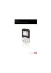
1
Low voltage AC drives
ABB general purpose drives
ACS310
0.5 to 30 hp/0.37 to 22 kW
Catalog
Selecting and ordering your drive
Build up your own ordering code using the type designation
key below or contact your local ABB drives sales office and let
them know what you want. Use page 3 as a reference section
for more information.
Type designation:
Product series
Ratings and types
Voltages
Constructions
Dimensions
Options
2 ABB general purpose drives ACS310 | Catalog
ACS310
-
0XU
-
XXXX
-
2
+
XXXX
Contents
ABB general purpose drives, ACS310
Introduction to ACS310, AC drives for pump and fan applications
4
Typical applications
5
Main features
6
Features, advantages and benefits
Ratings and types
6
7
Type designation
7
Voltages
7
Construction
7
Technical data
8
Dimensions and weights
9
Cabinet-mounted drives (IP20 UL Open)
Wall-mounted drives (NEMA 1/UL Type 1)
9
9
Cooling
10
Circuit protection
11
Control connections
12
Application macros
Options
12
13
How to select options
13
User interfaces
14
Protection and installation
14
Serial communication
15
Extension module
15
DriveWindow Light
16
FlashDrop tool
17
Input chokes
18
EMC filters
18
Taking care of your drives, caring about your business
19
Catalog | ABB general purpose drives ACS310 3
Introduction to ACS310
AC drives for pump and fan applications
ACS310
-
0XU
-
XXXX
-
2
ABB general purpose drives, ACS310, are dedicated to variable
torque applications such as booster pumps and centrifugal fans.
The drive’s dedicated pump and fan features lower operating
costs, boost energy efficiency and reduce CO2 emissions.
Included among these features are built-in PID controllers and
PFC (pump and fan control) that varies the drive’s performance
in response to changes in pressure, flow or other external data.
Among the pre-programmed protection functions is pump
cleaning. This prevents pump and pipes clogging by initiating a
sequence of forward and reverse runs of the pump to clean the
impeller.
Within pumping applications, energy savings up to 50 percent
can be achieved compared to direct-on-line motor-driven
systems that use mechanical flow control methods. The ABB
general purpose drives provide built-in features for efficient
energy management. Energy savings can be easily monitored
using the built-in counters that display energy savings in
kilowatt hours and saved carbon dioxide emissions. The savings
can also be displayed in local currencies.
4 ABB general purpose drives ACS310 | Catalog
+
XXXX
The compact design and uniform dimensions make cabinet
mounting of the drive straightforward, thereby providing a
speedy and space saving installation. The ACS310 drives
have an embedded Modbus interface for system monitoring
that saves the cost of external fileldbus devices and enables
to integrate the drives easily with PLC. When combined
with preprogrammed application macros, an intuitive user
interface and several assistant screens, installation time is
further reduced while speeding up parameter setting and drive
commissioning.
The ACS310 drives meet the needs of logistical and technical
distributors as well as the requirements of end users with
pumping and ventilation applications. The drives are supported
by one of the most extensive global sales and service networks
with presence in over 100 countries.
Highlights
− Powerful set of pump and fan features
− Boosted energy efficiency
− Tailored for cabinet installations
− Clever drive commissioning assistants and convenient user
interface
− Worldwide availability and service
Typical applications
The ACS310 drive is specifically designed to meet the variable
torque loads demanded by centrifugal fans and pumps. The
result is maximum application uptime, reduced maintenance cost
and higher energy savings.
Irrigation systems, whether agricultural, horticultural or those
used on golf courses, have a common demand for a reliable
and efficient flow of water.
The built-in real-time clock provides true time and date stamps
that control the start and stop times of watering based on the
daily demand profile. Soft pipe filling provides a pump with
soft-start, enabling a smooth build-up of flow in pipes while
increasing the life time of the pipe work and pumping system.
A booster pump system is designed to boost supplied water
pressure to a predetermined level in water and wastewater
plants. The ACS310 drive features pump and fan control (PFC)
for use where several parallel pumps are operated together and
the required flow rate is variable.
PID control is available to allow the process to accurately
maintain a pressure setpoint by adjusting the control outputs,
thus allowing for precise control within difficult processes.
A sleep & boost function detects slow rotation and runs the
pump to boost pressure prior to shutdown. The pressure
is continuously monitored and pumping restarts when the
pressure falls below the minimum level.
Level control is used to adjust the filling or emptying of storage
tanks. Storage tanks may be located within processes such as
pulp and paper for supplying process fluids like wastewater. The
drive has signal supervision for level control and a pipe cleaning
feature, thereby preventing solids from building up on pumps
impellers or the tank walls.
Storage tanks are often mounted in narrow locations, with limited
space for components like AC drives. The compact size and
various mounting methods of the ACS310 drives enables easy
installation and space savings in new installations and retrofits.
Wood drying kilns´ have a high demand for powerful and
efficient ventilation to dry out the wood. In wood kilns centrifugal
fans and AC drives are used to control the air flow demand. To
increase the kilns´ capacity, multiple fans may be controlled via
one drive by using the pump and fan control (PFC) feature. At
the start of the drying process, the relative humidity is high thus
there is a demand for higher air flow rates. As the wood dries
out the auxiliary fans may shut-down, thereby saving energy and
reducing maintenance.
Catalog | ABB general purpose drives ACS310 5
Main features
ACS310
-
0XU
-
XXXX
-
2
+
XXXX
Feature
Advantage
Benefit
Pump and fan control
One drive controls several pumps or fans and eliminates the need
Saves cost of additional drives and external PLC.
(PFC) feature to control
for an external programmable logic controller.
pumps and fans in parallel
Reduces motor stress and increases lifetime when auxiliary motors
Longer life for pump or fan systems while reducing
are driven according to the needed pump/fan capacity.
maintenance time and costs.
Interlock function enables one motor to be disengaged from the
Maintenance can be carried out safely without stopping
mains supply while others continue operating in parallel.
the process.
Soft pump and fan control
Reduces unwanted pressure peaks in pumps and pipelines when
Reduces maintenance costs.
feature (SPFC)
an auxiliary motor is started.
Longer life for pump or fan systems.
Reduces inrush current to the power network while connecting
Smoother processes.
new auxiliary motors.
Pump protection functions
Integrated protection and control with preprogrammed features
Reduces maintenance costs.
like pipe cleaning, pipefill, inlet/outlet pressure supervision and
Longer life and reliable operation of pump systems.
detection of under or over load for preventive maintenance.
Improves process control and system reliability. Integrates system
protection.
Smoother processes: improved and optimized system. Longer life
for pump and fan systems, reduced maintenance costs.
PID controllers
Varies the drive’s performance according to the need of the
Enhances production output, stability and accuracy.
application.
Embedded Modbus
No need for external fieldbus options.
EIA-485 fieldbus interface
Integrated and compact design.
Saves costs of external fieldbus devices.
Increases reliability.
On/off cooling fan control
Cooling fan rotates only when the drive is running, thereby cooling
Silent operation.
only when needed.
Improves drive’s energy efficiency.
Software controlled phase
Fast and easy way to change the phase order of the motor
Time savings as there is no need to change the output
inversion
rotation.
cable order manually.
Short parameter menu
Only the most needed drive parameters are shown on the drive’s
Time savings as the user quickly sees the most important
view
parameter view. Complete parameter view can be changed by
parameters.
setting one parameter.
Fast commissioning of the drive.
Energy optimizer
Improved motor efficiency with intelligent drive control method,
Boosts energy efficiency due to lower motor currents.
especially while operating on partial centrifugal loads.
Reduces audible noise from the motor.
Energy efficiency counters
Several counters to illustrate saved energy (kWh), carbon-dioxide
Shows direct impact on energy bill and helps control
emissions (CO 2) and cost in local currency.
operational expenditure (OPEX).
Full output current at
The drive can be operated in ambient temperatures up to
Optimized drive dimensioning for wide temperature
50 °C ambient
50 °C without derating the output current.
ranges.
Load analyzer
Load analyzer saves process data, such as current and
Optimized dimensioning of the drive, motor and process.
torque values, which can be used to analyze the process and
dimensioning of the drive and motor.
Compact size and flexible
The high power-to-size ratio of the drive facilitates efficient cabinet
mounting options
space usage.
Space savings.
Optimum installation layout.
Flexible installation with screw or DIN rail mounting.
Drive can be installed sideways or side-by-side.
User interfaces
Assistant control panel with clear alphanumerical dynamic menus,
Different control panels available according to
real time clock and 14 languages. Basic panel with numerical
functionality needs.
display.
Maintenance assistant
Monitors consumed energy (kWh), running hours or motor rotation.
Assists in preventive maintenance of the drive, motor or
Commissioning assistants
Easy setup of parameters for PID controllers, real-time clock, serial
Time savings with reduced need to set the parameters
communication, drive optimizer and drive startup.
manually.
Motor output and I/O protected against wiring faults.
Latest solution to protect the drive and offer trouble free
Protection against unstable supply networks.
use and the highest quality.
run application.
Ensures all required parameters are set.
Drive protection
Coated boards as standard.
6 ABB general purpose drives ACS310 | Catalog
Ratings and types
ACS310
-
0XU
-
XXXX
-
2
Type designation
This is the unique reference number (shown above and in
column 5. left) that clearly identifies the drive by power rating
and frame size. Once the drive’s type designation has been
selected, the frame size (column 6) can be used to determine
the drive dimensions, shown on the next page.
+
XXXX
Construction
“00U” within the type designation (shown above) varies
depending on the drive phase and EMC filtering. Choose below
the one you need.
01 = 1-phase
03 = 3-phase
Voltages
ACS310 is available in two voltage ranges:
2 = 200 to 240 V
4 = 380 to 480 V
Insert either “2” or “4”, depending on your chosen voltage, into
the type designation shown above.
Ratings
Type designation
PN
PN
I 2N
hp
kW
A
1)
I LD
2)
Frame
size
A
1-phase AC supply, 200 to 240 V
0.5
0.37
2.4
2.3
ACS310-01U-02A4-2
R0
1.0
0.75
4.7
4.5
ACS310-01U-04A7-2
R1
1.5
1.1
6.7
6.5
ACS310-01U-06A7-2
R1
2.0
1.5
7.5
7.2
ACS310-01U-07A5-2
R2
3.0
2.2
9.8
9.4
ACS310-01U-09A8-2
R2
3-phase AC supply, 200 to 240 V
2.6
2.4
0.5
0.37
ACS310-03U-02A6-2
R0
0.75
0.55
3.9
3.5
ACS310-03U-03A9-2
R0
1.0
0.75
5.2
4.7
ACS310-03U-05A2-2
R1
1.5
1.1
7.4
6.7
ACS310-03U-07A4-2
R1
2.0
1.5
8.3
7.5
ACS310-03U-08A3-2
R1
3.0
2.2
10.8
9.8
ACS310-03U-10A8-2
R2
5.0
4.0
19.4
17.6
ACS310-03U-19A4-2
R2
7.5
5.5
26.8
24.4
ACS310-03U-26A8-2
R3
10.0
7.5
34.1
31.0
ACS310-03U-34A1-2
R4
15.0
11.0
50.8
46.2
ACS310-03U-50A8-2
R4
3-phase AC supply, 380 to 480 V
1.3
1.2
0.5
0.37
ACS310-03U-01A3-4
R0
1.9
ACS310-03U-02A1-4
R0
0.75
0.55
2.1
1.0
0.75
2.6
2.4
ACS310-03U-02A6-4
R1
1.5
1.1
3.6
3.3
ACS310-03U-03A6-4
R1
2.0
1.5
4.5
4.1
ACS310-03U-04A5-4
R1
3.0
2.2
6.2
5.6
ACS310-03U-06A2-4
R1
5.0
4.0
9.7
8.8
ACS310-03U-09A7-4
R1
7.5
5.5
13.8
12.5
ACS310-03U-13A8-4
R3
10.0
7.5
17.2
15.6
ACS310-03U-17A2-4
R3
15.0
11.0
25.4
23.1
ACS310-03U-25A4-4
R3
20.0
15.0
34.1
31
ACS310-03U-34A1-4
R4
25.0
18.5
41.8
38
ACS310-03U-41A8-4
R4
30.0
22.0
48.4
44
ACS310-03U-48A4-4
R4
1)
2)
I2N maximum continuous output current at ambient temperature of +40 °C.
No overloadability, derating 1% for every additional 1 °C up to +50 °C.
ILD continuous output current at max ambient temperature of +50 °C.
10% overloadability for one minute every ten minutes.
Catalog | ABB general purpose drives ACS310 7
Technical data
ACS310
-
0XU
-
XXXX
-
Mains connection
Voltage and
power range
Frequency
2
+
XXXX
Programmable control connections
1-phase, 200 to 240 V ± 10%
0.5 to 3 hp (0.37 to 2.2 kW)
3-phase, 200 to 240 V ± 10%
0.5 to 15 hp (0.37 to 11 kW)
3-phase, 380 to 480 V ± 10%
0.5 to 30 hp (0.37 to 22 kW)
48 to 63 Hz
Motor connection
Voltage
3-phase, from 0 to U supply
Frequency
0 to 500 Hz
Continuous loading
capability
I 2N maximum continuous output current at
ambient temperature of +40 °C.
No overloadability, derating 1% for every
additional 1 °C up to 50 °C.
I LD continuous output current at max
ambient temperature of +50 °C.
10% overloadability for one minute every
ten minutes.
At start 1.8 x I2N for 2 s
Two analog inputs
Voltage signal
Unipolar
Bipolar
Current signal
Unipolar
Bipolar
Resolution
Accuracy
0 (4) to 20 mA, R in = 100 Ω
-20 to 20 mA, R in = 100 Ω
0.1%
± 1%
One analog output
0 (4) to 20 mA, load < 500 Ω
Auxiliary voltage
24 V DC ± 10%, max. 200 mA
Five digital inputs
Input impedance
12 to 24 V DC with internal or external
supply, PNP and NPN, pulse train
0 to 16 kHz
2.4 kΩ
One relay output
Type
Maximum switching voltage
Maximum switching current
Maximum continuous current
NO + NC
250 V AC/30 V DC
0.5 A/30 V DC; 5 A/230 V AC
2 A rms
Transistor output
30 V DC
100 mA/30 V DC, short circuit
10 Hz to 16 kHz
1 Hz
0.2%
Switching frequency
Default
Selectable
4 kHz
4 to 16 kHz with 4 kHz steps
Acceleration time
0.1 to 1800 s
Deceleration time
0.1 to 1800 s
Motor control method
Scalar U/f
One digital output
Type
Maximum switching voltage
Maximum switching current
Frequency
Resolution
Accuracy
14 to 122 o F (-10 to 50 o C), no frost
allowed
Fieldbus
Cable
Rated current available at 0 to 1000 m
(0 to 3281 ft) reduced by 1% per 100 m
(328 ft) over 1000 to 2000 m
(3281 to 6562 ft)
Termination
Isolation
Transfer rate
Communication type
Protocol
Environmental limits
Ambient temperature
Altitude
Output current
o
0 (2) to 10 V, Rin > 312 kΩ
-10 to 10 V, R in > 312 kΩ
Serial communication
Modbus EIA-485, embedded
Shielded twisted pair, impedance 100 to
150 ohms
Daisy-chained bus, without dropout lines
Bus interface isolated from drive
1.2 to 76.8 kbit/s
Serial, asynchronous, half duplex
Modbus
Relative humidity
Lower than 95% (without condensation)
Degree of protection
IP20/optional NEMA 1 enclosure
Chokes
Enclosure colour
NCS 1502-Y, RAL 9002, PMS 420 C
AC input chokes
Contamination levels
IEC721-3-3
No conductive dust allowed
Class 1C2 (chemical gas es)
Class 1S2 (solid particles)
Class 2C2 (chemical gases)
Class 2S2 (solid particles)
Class 3C2 (chemical gases)
Class 3S2 (solid particles)
External option
For reducing THD in partial loads and to
comply with EN/IEC 61000-3-12
AC output chokes
External option
To achieve longer motor cables
Transportation
Storage
Operation
Product compliance
Low Voltage Directive 2006/95/EC
Machinery Directive 2006/42/EC
EMC Directive 2004/108/EC
Quality assurance system ISO 9001
Environmental system ISO 14001
UL, cUL, CE, C-Tick and GOST R approvals
RoHS compliant
8 ABB general purpose drives ACS310 | Catalog
Dimensions and weights
ACS310
-
0XU
-
XXXX
-
2
+
XXXX
Cabinet-mounted drives (IP20 UL open)
Frame size
H1
H2
H3
W
D
=
=
=
=
=
IP20 UL open
H1
H2
H3
W
D
in
in
in
in
in
Weight
lb
R0
6.65
7.95
9.41
2.76
6.34
2.4
R1
6.65
7.95
9.41
2.76
6.34
2.9
R2
6.65
7.95
9.41
4.13
6.5
3.3
R3
6.65
7.95
9.29
6.65
6.65
6.4
R4
7.13
7.95
9.61
10.24
6.65
9.7
H1
H2
H3
Height without fastenings and clamping plate
Height with fastenings but without clamping plate
Height with fastenings and clamping plate
Width
Depth
D
W
Wall-mounted drives (NEMA 1)
Frame size
H4
H5
W
D
=
=
=
=
NEMA 1
H4
H5
W
D
in
in
in
in
lb
R0
10.12
11.02
2.76
6.65
3.3
R1
10.12
11.02
2.76
6.65
3.7
R2
10.12
11.1
4.13
6.65
4.2
R3
10.24
11.77
6.65
6.97
7.7
R4
10.63
12.6
10.24
6.97
11
Height with fastenings and NEMA 1 connection box
Height with fastenings, NEMA 1 connection box and hood
Width
Depth
Weight
H4
H5
D
W
Catalog | ABB general purpose drives ACS310 9
Cooling
Cooling
ACS310 is fitted with cooling fans as standard. The cooling air
must be free from corrosive substances and must not be above
the maximum ambient temperature of 50 °C.
Cooling air flow
Type designation
For more specific limits see the Technical data - Environmental
limits in this catalogue.
Free space requirements
Frame
Heat dissipation
Air flow
Enclosure type
Space above
Space below
Space on left/right
All frame sizes
in
2.95
in
2.95
in
0
size
3
[W]
BTU/hr1)
ft /min
3
m /h
1-phase AC supply, 200 to 240 V
2)
2)
ACS310-01U-02A4-2
R0
48
163
-
ACS310-01U-04A7-2
R1
72
247
14
24
ACS310-01U-06A7-2
R1
97
333
14
24
ACS310-01U-07A5-2
R2
101
343
12
21
ACS310-01U-09A8-2
R2
124
422
12
21
42
142
-
2)
-
2)
2)
-
2)
-
3-phase AC supply, 200 to 240 V
ACS310-03U-02A6-2
R0
ACS310-03U-03A9-2
R0
54
183
-
ACS310-03U-05A2-2
R1
64
220
14
24
ACS310-03U-07A4-2
R1
86
295
14
24
ACS310-03U-08A3-2
R1
88
302
12
21
ACS310-03U-10A8-2
R2
111
377
12
21
ACS310-03U-19A4-2
R2
180
613
31
52
ACS310-03U-26A8-2
R3
285
975
42
71
ACS310-03U-34A1-2
R4
328
1119
57
96
ACS310-03U-50A8-2
R4
488
1666
57
96
35
121
-
2)
2)
3-phase AC supply, 380 to 480 V
ACS310-03U-01A3-4
1)
2)
R0
-
2)
-
2)
ACS310-03U-02A1-4
R0
40
138
-
ACS310-03U-02A6-4
R1
50
170
8
13
ACS310-03U-03A6-4
R1
60
204
8
13
ACS310-03U-04A5-4
R1
69
235
8
13
ACS310-03U-06A2-4
R1
90
306
11
19
ACS310-03U-09A7-4
R1
127
433
14
24
ACS310-03U-13A8-4
R3
161
551
31
52
ACS310-03U-17A2-4
R3
204
697
31
52
ACS310-03U-25A4-4
R3
301
1029
42
71
ACS310-03U-34A1-4
R4
408
1393
57
96
ACS310-03U-41A8-4
R4
498
1700
57
96
ACS310-03U-48A4-4
R4
588
2007
57
96
BTU/hr = British Thermal Unit per hour. BTU/hr is approximately 0.293 Watts.
Frame size R0 with free convection cooling.
10 ABB general purpose drives ACS310 | Catalog
Circuit protection
Circuit protection
Standard fuses can be used with ABB general purpose drives.
For input fuse connections see table below.
Selection table
Type designation
Frame
size
IEC fuses
UL fuses
Fuse
type
[A]
1)
UL Class T or
Manual motor protector
MMP type code
3) 4)
Trip current
CC (600 V)
setting
[A]
[A]
1-phase AC supply, 200 to 240 V
5)
ACS310-01U-02A4-2
R0
10
gG
10
ACS310-01U-04A7-2
R1
16
gG
20
MS451-16E
11.4
ACS310-01U-06A7-2
R1
MS132-6.3 & S1-M3-25
6.1
16/20
2)
gG
25
MS451-20E
16.1
gG
30
MS451-20E
16.8
gG
35
MS451-25E
21.0
ACS310-01U-07A5-2
R2
20/25
2)
ACS310-01U-09A8-2
R2
25/35
2)
Other fuse types can be used if they
meet the ratings and the melting curve
of the fuse does not exceed the melting
curve of the fuse mentioned in this
table.
1)
According to IEC-60269 standard.
2)
If 50% overload capacity is needed,
use the bigger fuse alternative.
3)
All manual motor protectors listed are
Type E self-protected up to 65 kA.
4)
Manual motor protectors may require
adjusting the trip limit from the factory
setting at or above the drive input
Amps to avoid nuisance tripping. If
the manual motor protector is set to
the maximum current trip level and
nuisance tripping is occurring, then
select the next size MMP. (MS132-10
is the highest size in MS132 frame
size to meet Type E at 65 kA; the next
size up is the MS451-16E).
5)
S1-M3-25 line side feeder terminal is
needed with manual motor protector
to meet Type E self protection
class according to UL and cUL
requirements.
6)
480Y/277V only.
3-phase AC supply, 200 to 240 V
ACS310-03U-02A6-2
R0
10
gG
10
MS132-6.3 & S1-M3-25
5)
4.7
ACS310-03U-03A9-2
R0
10
gG
10
MS132-10 & S1-M3-25
5)
6.7
MS132-10 & S1-M3-25
5)
8.4
ACS310-03U-05A2-2
R1
10
gG
15
ACS310-03U-07A4-2
R1
16
gG
15
MS451-16E
13.0
ACS310-03U-08A3-2
R1
16
gG
15
MS451-16E
13.2
ACS310-03U-10A8-2
R2
16
gG
20
MS451-20E
15.7
ACS310-03U-19A4-2
R2
25
gG
35
MS451-32E
27.3
ACS310-03U-26A8-2
R3
63
gG
60
MS451-50E
45.0
ACS310-03U-34A1-2
R4
80
gG
80
MS495-63E
55.0
ACS310-03U-50A8-2
R4
100
gG
100
MS495-90E
76.0
3-phase AC supply, 380 to 415 V
6)
ACS310-03U-01A3-4
R0
10
gG
10
MS132-2.5 & S1-M3-25
5)
2.4
ACS310-03U-02A1-4
R0
10
gG
10
MS132-6.3 & S1-M3-25
5)
4.0
ACS310-03U-02A6-4
R1
10
gG
10
MS132-6.3 & S1-M3-25
5)
4.5
6.6
ACS310-03U-03A6-4
R1
10
gG
10
MS132-10 & S1-M3-25
5)
ACS310-03U-04A5-4
R1
16
gG
15
MS132-10 & S1-M3-25
5)
ACS310-03U-06A2-4
R1
16
gG
15
MS451-16E
10.6
ACS310-03U-09A7-4
R1
20
gG
25
MS451-20E
15.0
ACS310-03U-13A8-4
R3
25
gG
30
MS451-25E
20.7
ACS310-03U-17A2-4
R3
35
gG
35
MS451-32E
24.3
ACS310-03U-25A4-4
R3
50
gG
50
MS451-40E
34.0
ACS310-03U-34A1-4
R4
80
gG
80
MS495-63E
57.0
ACS310-03U-41A8-4
R4
100
gG
100
MS495-75E
67.0
ACS310-03U-48A4-4
R4
100
gG
100
MS495-90E
74.0
3-phase AC supply, 440 to 480 V
7.6
6)
ACS310-03U-01A3-4
R0
10
gG
10
MS132-2.5 & S1-M3-25
5)
2.0
ACS310-03U-02A1-4
R0
10
gG
10
MS132-4.0 & S1-M3-25
5)
3.3
ACS310-03U-02A6-4
R1
10
gG
10
MS132-6.3 & S1-M3-25
5)
3.8
ACS310-03U-03A6-4
R1
10
gG
10
MS132-6.3 & S1-M3-25
5)
5.5
ACS310-03U-04A5-4
R1
16
gG
15
MS132-10 & S1-M3-25
5)
6.3
ACS310-03U-06A2-4
R1
16
gG
15
MS132-10 & S1-M3-25
5)
ACS310-03U-09A7-4
R1
20
gG
25
MS451-16E
12.0
ACS310-03U-13A8-4
R3
25
gG
30
MS451-20E
17.0
ACS310-03U-17A2-4
R3
35
gG
35
MS451-25E
20.0
ACS310-03U-25A4-4
R3
50
gG
50
MS451-32E
28.0
ACS310-03U-34A1-4
R4
80
gG
80
MS451-50E
48.0
ACS310-03X-41A8-4
R4
100
gG
100
MS495-63E
56.0
ACS310-03X-48A4-4
R4
100
gG
100
MS495-63E
61.0
8.8
Catalog | ABB general purpose drives ACS310 11
Control connections
ACS310
-
0XU
-
XXXX
-
2
Application macros
Application macros are preprogrammed parameter sets. While
starting up the drive, the user typically selects one of the
macros that is best suited for the application. The diagram
below gives an overview of ACS310 control connections and
shows the default I/O connections for the ABB standard macro.
−
−
−
−
−
−
−
−
+
XXXX
In addition to the standard macros the user can create three
user macros. The user macro allows the user to save the
parameter settings for later use.
The diagram below gives an overview of ACS310 control
connections. Please refer to the ACS310 user’s manual for more
detailed information.
ABB standard macro
3-wire macro
Alternative macro
Motor potentiometer
Hand/auto macro
PID control macro
PFC control macro
SPFC control macro
Typical I/O connections
8
ACS310: X1
Control panel
(RJ-45)
1
SCR
Analog input 1
2
AI1
3
GND
0 to 10 V
Ramp Const. Fwd/
pair sel Speed 1 Rev
S1
AI1
AI2
Screen
Reference voltage
+10 V DC, max 10 mA
4
mA
V
+10 V
Analog input 2
5
AI2
6
GND
9
+24 V
10
GND
11
DCOM
12
DI1
13
DI2
14
DI3
Aux. voltage output
+24 V DC, max. 200 mA
PROGRAMMABLE
DIGITAL INPUTS
15
DI5 can also be used
DI4
16
DI5
23
SHIELD
GND
+24 V
10 GND
11 DCOM
Analog output
0 to 20 mA
AO
12 DI1
13 DI2
14 DI3
15 DI4
16 DI5
PROGRAMMABLE RELAY
AND DIGITAL OUTPUTS
DI configuration NPN connected (sink)
ROCOM
Relay output
250 V AC/30 V DC/6 A
RONC
RONO
+ 24 V
ACS310: X1
9
DOSRC
Digital/frequency output,
PNP transistor type
30 V DC, max. 100 mA
DOOUT
DOGND
Const.
speed 1
Fwd/ Start/
Rev Stop
+24 V
10 GND
11 DCOM
12 DI1
as a frequency input
13 DI2
6
Modbus RTU
(EIA-485)
24
B J701
25
A
26
GND_A
FlashDrop
EMC
EMC filter grounding screw
VAR
Varistor grounding screw
PE
L1
U1
U2
L2
V1
V2
W1
W2
L3
EMC
filter
12 ABB general purpose drives ACS310 | Catalog
14 DI3
Output relay
module MREL-01
15 DI4
0V
PE
3-phase
Input
power supply, choke
200 to
480 V AC
9
Start/
Stop
M
3~
AC motor
Output
choke
16 DI5
DI configuration PNP connected (source) with external
power supply
Options
ACS310
-
0XU
-
XXXX
-
2
+
XXXX
How to select options
The options shown in the table below are available within the
ACS310 range. The control panels have an associated 4-figure
option code, which is shown in the second column.
It is this code that replaces XXXX in the type code above.
Options
Ordering code
Description
Model
*)
NEMA 1/UL type 1 (R0, R1, R2)
MUL1-R1
*)
NEMA 1/UL type 1 (R3)
MUL1-R3
*)
NEMA 1/UL type 1 (R4)
MUL1-R4
J400
Assistant control panel
ACS-CP-A
J404
Basic control panel
ACS-CP-C
*)
Panel mounting kit
ACS/H-CP-EXT
*)
Panel holder mounting kit
OPMP-01
L511
Relay output extension module. Option includes three (3)
MREL-01
Protection class
Control panel
Panel mounting kit
Extension modules
additional relay outputs.
Tools
External options
Remote monitoring
*)
FlashDrop tool
MFDT-01
*)
DriveWindow Light
DriveWindow Light
*)
Input chokes
*)
EMC filters
*)
Ethernet adapter
*)
Ordering with a separate MRP code number.
1)
The ACS310 is compatible with ACS-CP-C basic control panel Rev M or later.
2)
The ACS310 is compatible with ACS-CP-A assistant control panel Rev E or later.
(New panel series manufactured since 2007 with serial number
XYYWWRXXXX, where year Y = 7 or greater and revision R = E, F, G, …)
SREA-01
Catalog | ABB general purpose drives ACS310 13
Options
User interfaces
ACS310
-
0XU
-
XXXX
-
2
+
XXXX
User interface
Panel cover
The purpose of the panel cover is to protect the drive’s
connection surfaces.The ACS310 drive is delivered with a panel
cover as standard. In addition there are two alternative control
panels available as options.
Basic control panel
The basic control panel features a single line numeric display.
The panel can be used to control the drive, set parameter
values or copy them from one drive to another.
Assistant control panel
The assistant control panel features a multilingual alphanumeric
display for easy drive programming. The control panel has
various assistants and an built-in help function to guide the
user. It includes a real time clock, which can be used during
fault logging and in controlling the drive, such as at start/stop.
The control panel can be used for copying parameters for back
up or for downloading to another drive. A large graphical display
and soft keys make it extremely easy to navigate.
Panel mounting kits
To attach the control panel to the outside of a larger enclosure,
two panel mounting kits are available. A simple and costefficient installation is possible with the ACS/H-CP-EXT kit,
while the OPMP-01 kit provides a more user-friendly solution,
including a panel platform that enables the panel to be removed
in the same way as a drive-mounted panel. The panel mounting
kits include all hardware required, including 3 meters extension
cables and installation instructions.
Basic control panel
Panel cover (included as standard)
Assistant control panel
Panel holder mounting kit OPMP-01
Protection and installation
NEMA 1 kit
The NEMA 1 kit includes a connection box for finger protection,
conduit tube installation, and a hood for protection against dirt
and dust.
Terminal cover
(included as standard)
Terminal cover
The terminal cover is for protection of the I/O connections.
Clamping plates
The clamping plates are used for protection against electrical
disturbances. The clamping plates with the clamps are included
in the drive package as standard.
NEMA 1 kit
14 ABB general purpose drives ACS310 | Catalog
Clamping plates
(included as standard)
Options
User interfaces
ACS310
-
0XU
-
XXXX
-
2
+
XXXX
Serial communication
The embedded Modbus EIA-485 fieldbus brings connectivity to
major automation systems. A single twisted pair cable avoids
large amounts of conventional cabling, thereby reducing costs
and increasing system reliability.
Removable clip for
labeling
Panel connector
Modbus TCP to Modbus RTU gateway
Additionally SREA-01 Ethernet adapter offers Modbus TCP to
Modbus RTU gateway functionality which enables Modbus TCP
connectivity to ACS310. Please refer to SREA-01 user’s guide
for more detailed information.
Extension module
MREL-01
ACS310 has one relay output as standard. The optional
MREL-01 module offers three additional relay outputs. The
outputs can be configured for different functions by setting
selected parameters.
MREL-01 connector
FlashDrop connection
EMC filter
grounding screw
(EMC)
Varistor
grounding screw
(VAR)
LEDs
Fieldbus connection
Modbus EIA-485
Analog I/O
Relay output
Digital output
Digital inputs
SREA-01 Ethernet adapter
SREA-01 Ethernet adapter with remote monitoring access
can send process data, data logs and event messages
independently, without a PLC or a dedicated on-site computer.
It has an internal web server for configuration and drive access.
In remote locations without qualified service people on-site it
is vital to be able to monitor the drive remotely. Monitoring and
diagnostics routines can be easily implemented with ABB’s
remote monitoring tool. The remote monitoring tool enables
to connect multiple drives to Ethernet, to collect operational
data from the process and send the collected data to a central
location for process monitoring and further analysis.
Extension module MREL-01
SREA-01 Ethernet adapter
Catalog | ABB general purpose drives ACS310 15
Options
Software tools
A separate order line and type designation is required for
any of these software tool options.
DriveWindow Light
DriveWindow Light is an easy-to-use startup and maintenance
tool for ACS310 drives. It can be used in an offline mode, which
enables parameter setting at the office even before going to
the actual site. The parameter browser enables viewing, editing
and saving of parameters. The parameter comparison feature
makes it possible to compare parameter values between the
drive and saved parameter files. With the parameter subset you
can create your own parameter sets. Controlling the drive is one
of the features in DriveWindow Light. With this software tool,
you can monitor up to four signals simultaneously. This can be
done in both graphical and numerical format. DriveWindow Light
version 2.9 or later is compatible with ACS310 drives.
Startup wizards
Startup wizards make the setting of parameters easy. Simply
launch the wizard, select an appropriate assistant eg, for setting
analog outputs, and all parameters related to this function are
shown together with help pictures.
16 ABB general purpose drives ACS310 | Catalog
Highlights
− Editing, saving and downloading parameters
− Graphical and numerical signal monitoring
− Drive control
− Startup wizards
DriveWindow Light requirements
− Windows NT/2000/XP/Vista/Windows 7
− Serial port from a PC
− Control panel connector
Options
External
A separate order line and type designation is required for
any of these external options.
FlashDrop tool
FlashDrop is a powerful palm sized tool for fast and easy
parameter selecting and setting. It gives the possibility to
hide selected parameters to protect the machine. Only the
parameters needed in the application are shown. The tool can
copy parameters between two drives or between a PC and a
drive. All the above can be done without a power connection to
the drive – in fact, it is not even necessary to unpack the drive.
DrivePM requirements
− Windows 2000/XP/Vista/Windows 7
− Serial port from a PC
FlashDrop package includes
− FlashDrop tool
− DrivePM software on a CD-rom
− User’s manual in English and in pdf-format on the CD-rom
− Cable OPCA-02 for connection between the PC and
FlashDrop tool
− Battery charger
DrivePM
DrivePM (Drive parameter manager) is a tool to create, edit and
copy parameter sets for FlashDrop. For each parameter/group
the user has a possibility to hide it, which means that the drive
user does not see the parameter/group at all. DrivePM version
1.2 is compatible with ACS310 drives.
FlashDrop tool
Catalog | ABB general purpose drives ACS310 17
Options
External
A separate order line and type designation is required for
any of these external options.
A separate order line and type designation is required for
any of these external options.
Input chokes
An input choke smoothens the wave shape of mains current
and reduces total harmonic distortion (THD). Together with the
input choke, the ACS310 is designed to fulfill the requirements
of the harmonics standard EN/IEC 61000-3-12. In addition, the
input choke provides improved protection against mains voltage
transients.
EMC filters
The ACS310’s internal EMC filter is designed to meet category
C3 requirements of EN/IEC 61800-3 standard. External
EMC filters are used to enhance the drives electromagnetic
performance in conjunction with its internal filtering. Maximum
motor cable length depends on required electromagnetic
performance, according to the table below.
Type
Frame
Input
I 1N
designation
size
choke
without
ACS310-
choke
I 1N
I TH
L
with
choke
[A]
1)
[A]
Type
Frame
Filter
Cable length 1) with
Cable length1)
designation
size
type
external EMC filter
without external
ACS310[A]
EMC filter
[mH]
1-phase AC supply, 200 to 240 V
C1
C2
C3
C3
C4
[m]
[m]
[m]
[m]
[m]
01U-02A4-2
R0
CHK-A1
6.1
4.5
5
8.0
01U-04A7-2
R1
CHK-B1
11.4
8.1
10
2.8
01U-02A4-2
R0
RFI-11
10
30
-
30
30
01U-06A7-2
R1
CHK-C1
16.1
11
16
1.2
01U-04A7-2
R1
RFI-12
10
30
50
30
50
01U-07A5-2
R2
CHK-C1
16.8
12
16
1.2
01U-06A7-2
R1
RFI-12
10
30
50
30
50
01U-09A8-2
R2
CHK-D1
21
15
25
1.0
01U-07A5-2
R2
RFI-13
10
30
50
30
50
01U-09A8-2
R2
RFI-13
10
30
50
30
50
1-phase AC supply, 200 to 240 V
3-phase AC supply, 200 to 240 V
03U-02A6-2
R0
CHK-01
4.7
2.6
4.2
6.4
03U-03A9-2
R0
CHK-02
6.7
3.5
7.6
4.6
03U-02A6-2
R0
RFI-32
10
30
-
30
30
03U-05A2-2
R1
CHK-03
8.4
4.2
13
2.7
03U-03A9-2
R0
RFI-32
10
30
-
30
30
03U-07A4-2
R1
CHK-03
13
6.1
13
2.7
03U-05A2-2
R1
RFI-32
10
30
50
30
50
03U-08A3-2
R1
CHK-04
13.2
6.9
22
1.5
03U-07A4-2
R1
RFI-32
10
30
50
30
50
03U-10A8-2
R2
CHK-04
15.7
9.2
22
1.5
03U-08A3-2
R1
RFI-32
10
30
50
30
50
03U-19A4-2
R2
CHK-04
27.3
13.3
22
1.5
03U-10A8-2
R2
RFI-32
10
30
50
30
50
03U-26A8-2
R3
CHK-06
45
20.9
47
0.7
03U-19A4-2
R2
RFI-33
10
30
50
30
50
03U-34A1-2
R4
CHK-06
55
26.2
47
0.7
03U-26A8-2
R3
RFI-34
10
30
50
30
50
03U-50A8-2
R4
CHK-06
76
41
47
0.7
03U-34A1-2
R4
RFI-34
10
30
50
30
50
03U-50A8-2
R4
RFI-34
10
30
50
30
50
3-phase AC supply, 200 to 240 V
3-phase AC supply, 380 to 480 V
03U-01A3-4
R0
CHK-01
2.4
1.3
4.2
6.4
03U-02A1-4
R0
CHK-01
4.9
2
4.2
6.4
03U-01A3-4
R0
RFI-32
30
30
-
30
30
R0
RFI-32
30
30
-
30
30
3-phase AC supply, 380 to 480 V
03U-02A6-4
R1
CHK-01
4.5
2.5
4.2
6.4
03U-02A1-4
03U-03A6-4
R1
CHK-01
6.6
3.5
4.2
6.4
03U-02A6-4
R1
RFI-32
50
50
50
30
50
03U-04A5-4
R1
CHK-02
7.6
3.8
7.6
4.6
03U-03A6-4
R1
RFI-32
50
50
50
30
50
03U-06A2-4
R1
CHK-02
10.6
5.3
7.6
4.6
03U-04A5-4
R1
RFI-32
50
50
50
30
50
03U-09A7-4
R1
CHK-03
15
8.6
13
2.7
03U-06A2-4
R1
RFI-32
50
50
50
30
50
03U-13A8-4
R3
CHK-03
20.7
12.3
13
2.7
03U-09A7-4
R1
RFI-32
50
50
50
30
50
03U-17A2-4
R3
CHK-04
24.3
12.6
22
1.5
03U-13A8-4
R3
RFI-33
40
40
40
30
50
03U-25A4-4
R3
CHK-04
34
19.5
22
1.5
03U-17A2-4
R3
RFI-33
40
40
40
30
50
03U-34A1-4
R4
CHK-05
57
27.2
33
1.1
03U-25A4-4
R3
RFI-33
40
40
40
30
50
03U-41A8-4
R4
CHK-06
67
35.2
47
0.7
03U-34A1-4
R4
RFI-34
-
30
-
30
50
03U-48A4-4
R4
CHK-06
74
42
47
0.7
03U-41A8-4
R4
RFI-34
-
30
-
30
50
03U-48A4-4
R4
RFI-34
-
30
-
30
50
1)
Values at 50 Hz/230 V and at 50 Hz/400 V power supplies
I1N = Nominal input current
I TH = Nominal choke thermal current
L = Choke inductance
18 ABB general purpose drives ACS310 | Catalog
1)
Internal EMC filter must be connected with the EMC screw in the drive. When
the filter is not connected the C4 maximum cable lengths are allowed to be used.
Taking care of your drives, caring about your business
Whether a drive is a part of the product you sell or a
component in your production process, reliable and
efficient drive operation is key. You will find support
from your first meeting with ABB to the drive installation,
commissioning and maintenance, all the way up to the
eventual drive replacement and recycling. With offices
in over 90 countries, we are well placed to offer you
technical advice and local support.
Fast and reliable global delivery and
support
ABB drives, spare parts and services
are available worldwide and can be
purchased through the dedicated global
service and support network. More than
1400 companies, located throughout
the world and able to serve you locally
as well as provide you technical
support. These companies include
ABB’s own offices and authorized third
party channel companies
Installation and commissioning
We offer accurate advice and timely
support before and during installation.
ABB-certified engineers or third-party
channel companies can adjust the
drive parameters to meet the precise
demands of the application.
Check your local ABB contact from
www.abb.com/searchchannels
Preventive Maintenance
ABB recommends regular preventive
maintenance of drives throughout their
lifetime to ensure maximum availability
and minimum unplanned repair costs.
Drive preventive maintenance consists
of annual drive inspections and
component replacements according
to product specific maintenance
schedules.
Training services
To enhance personnel’s product
knowledge, and, with that, improve
plant safety and availability we offer a
selection of on-line courses. Check for
more information about ABB’s training
centers and the courses from
www.abb.com/abbuniversity.
Maintenance intervals
If installed in an appropriate environment, the drive requires very little maintenance.
The table lists the routine maintenance intervals recommended by ABB.
Maintenance
Interval
Reforming of capacitors
Every year when stored
Check of dustiness, corrosion and temperature
Every year
Cooling fan replacement (frame sizes R1 to R2)
Every three years
Check and tightening of the power terminals
Every six years
Consult your local ABB drives service representative for more details on the
maintenance or visit www.abb.com/drives.
Catalog | ABB general purpose drives ACS310 19
For more information please contact your local ABB
representative or visit:
www.abb.com/drives
© Copyright 2014 ABB. All rights reserved.
Specifications subject to change without notice.
3AUA0000159910 REV F US 10.4.2014 #17036
Contact us