1
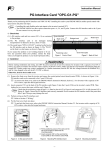
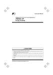
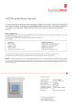
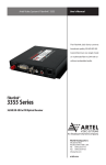
MOTOR CONTROL
Contactors and Thermal Overload Relays
FJ Series
62C1-E-0129a
The FJ Series is compact, safety, environmental friendly and
the world's smallest magnetic contactors.
(applied motor capacity: 400 VAC, 2.2 to 15 kW)
Compact
Compact and space-saving of magnetic contactor and thermal overload relay
Unit:mm
Contactors
World's smallest
Type :
FJ-B06
FJ-B09
FJ-B12
Type :
FJ-B18
81
48
49
Type :
FJ-B25
FJ-B32
81
81
80
45
53
43
Thermal overload relays
Type :
TK12B
49.5
Type :
TK18B
48.5
50
50.5
61
45
Motor rating
400V AC
Type :
TK32B
61
53
45
12A frame
18A frame
32A frame
FJ-B062.2kW
FJ-B093.7kW
FJ-B125.5kW
FJ-B187.5kW
FJ-B2511kW
FJ-B3215kW
Average of FJ-B06 to B32 types
Floor mounting area
73% of
previous models
Average of models with thermal overload relay
Volume
Floor mounting area
59% of
previous models
77% of
previous models
Volume
64% of
previous models
Compact DC operated Contactor
6 to 12 A frame products have been made much
smaller and lighter by adopting a newly developed
electromagnet.
Volume ratio
72% DOWN
Weight ratio
68% DOWN
Previous
DC operated types
48
45
2
49
DC operated types
• FJ-B06/G
• FJ-B09/G
• FJ-B12/G
Highly efficient electromagnet has been developed by using a computer simulation
with 3D magnetic field analysis so that AC and DC electromagnets have the same
appearance. (FJ-B06, B09, and B12 types)
Developing DC electromagnet
Developing compact and highly efficient electromagnet by using permanent magnet and making use of
coil energy
The DC electromagnet can be directly powered by 2.4 W through semiconductor output by minimizing
the leaked magnetic flux, distributing optimized magnetic flux, and satisfying demand for both less loss
and smaller size.
DC operated electromagnet
(FJ-B06/G, B09/G, and B12/G types)
Analyzing electromagnet
(distribution of magnetic flux density
and magnetic flux flow)
Developing AC electromagnet
A compact electromagnet has been developed by optimizing the sectional area of each iron core part
and excluding magnetic flux saturation and not having a wasteful shape
The iron-core-fixing rivets are optimally arranged in order to remove the impact on magnetic flux route
and the rivets can reduce eddy current loss.
This optimal design makes it possible to develop an energy saving electromagnet that
has 4.5 VA of electromagnetic capacity.
AC operated electromagnet
(FJ-B06, B09, and B12 types)
Analyzing electromagnet
(distribution of magnetic flux density
and magnetic flux flow)
Optimization was achieved through 3D thermal analysis and inversion mechanism
simulation.
3D thermal analysis simulation
To increase the accuracy of overcurrent detection, the
temperature rise in the built-in heater, the bimetal differential,
and the interphase thermal interference must be known in
detail.
To achieve this, interaction analysis of ”current, heat transfer,
bimetal differential” as shown in the Fig. 1 was performed.
Through research of the most efficient heat transfer path,
downsizing and reduction of power consumption for the
heaters were achieved.
Fig. 1 3D Thermal Analysis Simulation
New inversion mechanism
To downsize the relays and to stabilize high-performance
operating characteristics, a toggle inversion mechanism with
a tension spring was used for the inversion mechanism as
shown in the Fig. 2.
An inversion mechanism simulation was carried out
on the tension spring which is the core of the inversion
mechanism. The purpose was to verify that the input-output
characteristics of the loads and variants as well as the space
efficiency had been optimized.
In this way, the operating characteristics have been stabilized
while the spring size has been minimized to reduce the
necessary space.
Inversion Mechanism
Fig. 2 Inversion Mechanism Simulation
3
Safety
Standards
Terminal cover for finger protection
The terminal cover satisfies the requirements of
Machinery Directive EN60204-1 “Direct Contact
Prevention” concerning mechanical safety.
Standard models of the FJ Series are certified
by CCC and have obtained a CE mark, and that
is shown on the nameplate of the main unit.
Magnetic contactor equipped with mirror contact
Mirror contact conforms to the requirement for auxiliary contact that is intended to be included in the future
amendment to IEC 60947-4-1.
Mirror contact : Normally closed auxiliary contact,which cannot be in closed position simultaneously with the
normally open main contact.
Ecology
Environmental friendly
Energy Efficiency Label
Compliant with RoHS directive
(Restriction of Hazardous Substances in the EU)
The materials used do not contain any of the six substances that are
specified in the RoHS Directive or have less than the specified content
percentages of those substances.
China Energy Label
The FJ Series of magnetic contactors is highly energy efficient and they
have met the specified value defined by the Energy Efficiency Label
Management Method. Especially, FJ-B06, B09, and B12 types are energy
saving with an energy efficiency class of 2.
Frame
Sealed VA
Class
4
06
09
12
18
25
32
4.5
4.5
4.5
9
9
9
2
2
2
3
3
3
Many options
Auxiliary contact block
(front mounting)
Options for FJ-B06 to B12 types
SZ1FA11 type, SZ1FA11H type
Auxiliary contact block
Mechanical interlock unit
Auxiliary contact block with 2-pole
or 4-pole contacts adopting a
bifurcated contact. Easy to mount
on a magnetic contactor.
Mechanical interlock unit
SZ1KRW1W
The mechanical interlock unit
is used to interlock two
contactors for reversing.
One size fits all contactors.
Power Connection Kit
for Reversing
SZ1KRW1W
Front mounting
Cable kit for reversible circuit
between main circuit terminals for
two magnetic contactors.
Auxiliary contact block
(front mounting)
Options for FJ-B18 to B32 types
SZ-A
Auxiliary
contact block
(4 contacts)
type
Two and four auxiliary contact
blocks adopting a bifurcated
contact. Easy to mount on a
magnetic contactor.
Auxiliary
contact block
(2 contacts)
Coil-surge
suppression
unit
Auxiliary contact block
(side mounting)
SZ-A
type
Auxiliary contact block with 2
(1NO1NC) contacts adopting a
highly reliable auxiliary contact.
Easy to mount on a magnetic
contactor.
Auxiliary
contact block
(2 contacts)
Auxiliary
contact block
(2 contacts)
Interlock unit
SZ-RM type
Two magnetic contactors are
mechanically interlocked.
Reversible and easy to assemble.
Interlock
unit
Front mounting
Side mounting
Top mounting
Coil-surge suppression unit
SZ-Z
type
Built-in surge voltage suppression
elements (varistor, CR) while the
coil is turned off.
5
List of Products
Magnetic contactors
Series
Frame
Appearance
FJ Series
06
09
W
W
NE
Type
AC operated type
DC operated type
Max. motor capacity (kW)
220/230V
AC-3, IEC60947-4-1
380/400V
660/690V
Operational current (A)
220/230V
380/400V
660/690V
Conventional free air thermal current (rated thermal current) Ith (A)
Auxiliary contact arrangement
Dimensions
AC operated type
W × H × D (mm)
DC operated type
Optional unit
Auxiliary contact block
Front mounting
Side mounting
Coil surge suppression unit *1
Standards
FJ-B06
FJ-B06/G
1.5kW
2.2kW
2.7kW
6A
6A
3A
20A
1NO or 1NC
45 × 48 × 49
12
W
NE
FJ-B09
FJ-B09/G
2.2kW
4kW
4kW
9A
9A
5A
20A
1NO or 1NC
NE
FJ-B12
FJ-B12/G
3kW
5.5kW
5.5kW
12A
12A
6A
20A
1NO or 1NC
SZ1FA11 or SZ1FA11H
–
SZ1KZ1 to SZ1KZ5
V
Note: *1. Attach “S” behind the built-in order model of coil surge suppression unit.
Thermal overload relays
Type
Appearance
TK12BW
NE
Protection function
Tripping class
Ampere setting range (A) / code
Overload and phase loss
10A
0.1-0.15 [P10]
0.13-0.2 [P13]
0.18-0.27 [P18]
0.24-0.36 [P24]
0.34-0.52 [P34]
0.48-0.72 [P48]
0.64-0.96 [P64]
0.8-1.2 [P80]
0.95-1.45 [P95]
1.4-2.1 [1P4]
Applicable contactors
Dimensions W × H × D (mm)
FJ-B06, B09, B12
45 × 49.5 × 50
6
1.7-2.6 [1P7]
2.2-3.4 [2P2]
2.8-4.2 [2P8]
4-6 [004]
5-7.5 [005]
6-9 [006]
7-10.5 [007]
9-13 [009]
18
25
32
40
50
65
80
95
Coming soon
EW
EW
N
N
FJ-B18
FJ-B18/G
4kW
7.5kW
7.5kW
18A
18A
7A
25A
1NO or 1NC
43 × 81 × 80
43 × 81 × 107
SZ-A (2pole or 4pole)
SZ-AS1
SZ-Z1 to Z9
EW
N
FJ-B25
FJ-B32
FJ-B25/G
FJ-B32/G
5.5kW
7.5kW
11kW
15kW
7.5kW
7.5kW
25A
32A
25A
32A
9A
10A
32A
40A
1NO or 1NC 1NO or 1NC
53 × 81 × 81
53 × 81 × 108
FJ-B40
–
11kW
18.5kW
11kW
40A
40A
15A
50A
1NO1NC
64 x 90 x 96
–
FJ-B50
–
15kW
22kW
15kW
50A
50A
19A
60A
1NO1NC
64 x 90 x 96
–
FJ-B65
–
18.5kW
30kW
22kW
65A
65A
26A
65A
1NO1NC
64 x 90 x 96
–
FJ-B80
–
22kW
40kW
30kW
80A
80A
38A
100A
1NO1NC
77 x 110 x 111
–
FJ-B95
–
25kW
45kW
37kW
95A
95A
44A
105A
1NO1NC
77 x 110 x 111
–
SZ-Z31 to Z35
V
TK18B-
TK32BW
NE
W
NE
Overload and phase loss
Overload and phase loss
10A
10A
0.1-0.15 [P10] 1.7-2.6 [1P7]
0.1-0.15 [P10] 1.7-2.6 [1P7]
0.13-0.2 [P13] 2.2-3.4 [2P2]
0.13-0.2 [P13] 2.2-3.4 [2P2]
0.18-0.27 [P18] 2.8-4.2 [2P8] 0.18-0.27 [P18] 2.8-4.2 [2P8]
4-6 [004]
4-6 [004] 0.24-0.36 [P24]
0.24-0.36 [P24]
5-7.5 [005]
5-7.5 [005] 0.34-0.52 [P34]
0.34-0.52 [P34]
6-9 [006]
6-9 [006] 0.48-0.72 [P48]
0.48-0.72 [P48]
0.64-0.96 [P64] 7-10.5 [007] 0.64-0.96 [P64] 7-10.5 [007]
9-13 [009]
0.8-1.2 [P80]
9-13 [009]
0.8-1.2 [P80]
12-18 [012]
12-18 [012] 0.95-1.45 [P95]
0.95-1.45 [P95]
16-22 [016]
1.4-2.1 [1P4]
1.4-2.1 [1P4]
20-26 [020]
26-32 [026]
FJ-B18
FJ-B25, B32
45 × 48.5 × 61
53 × 50.5 × 61
7
Safety Considerations
• Operate (keep) in the environment specified in the operating instructions and manual. High temperature, high humidity, condensation, dust,
corrosive gases, oil, organic solvents, excessive vibration or shock might cause electric shock, fire, erratic operation or failure.
• For safe operation, before using the product read the instruction manual or user manual that comes with the product carefully or consult the
Fuji sales representative from which you purchased the product.
• Products introduced in this catalog have not been designed or manufactured for such applications in a system or equipment that will affect
human bodies or lives.
• Customers, who want to use the products introduced in this catalog for special systems or devices such as for atomic-energy control,
aerospace use, medical use, passenger vehicle, and traffic control, are requested to consult with Fuji Electric FA.
• Customers are requested to prepare safety measures when they apply the products introduced in this catalog to such systems or facilities
that will affect human lives or cause severe damage to property if the products become faulty.
• For safe operation, wiring should be conducted only by qualified engineers who have sufficient technical knowledge about electrical work or
wiring.
• Follow the regulations of industrial wastes when the product is to be discarded.
• For further questions, please contact your Fuji sales representative or Fuji Electric FA.
5-7, Nihonbashi Odemma-cho, Chuo-ku, Tokyo, 103-0011, Japan
URL http://www.fujielectric.co.jp/fcs/eng
Information in this catalog is subject to change without notice.
2013-05 PDF FOLS 62C1-E-0129a