
1
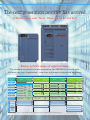
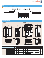
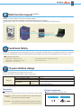
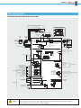
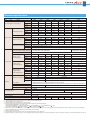
High Performance Inverter
New
F U J I I N V E RT E R S
The FRENIC-Ace is the inverter that produces excellent cost-performance;
maintains high performance through optimal design.
In this way, it can be applied to various machines and devices.
24A1-E-0042
The next generation inverter has arrived
Introducing our New Standard Inverter!
Enjoy a full range of applications
The standard inverter for the next generation, the FRENIC-Ace, can be used
in almost any type of application—from fans and pumps to specialized machinery.
3-phase 400V series
Nominal
applied motor
[kW]
ND rating
Model
HD rating
Rated output
current
Model
HND rating
Rated output
current
Model
HHD rating
Rated output
current
FRN0059E2S-4
39A
45A
FRN0059E2S-4
45A
FRN0072E2S-4
45A
30
FRN0059E2S-4
59A
FRN0072E2S-4
60A
FRN0072E2S-4
60A
FRN0085E2S-4
60A
37
FRN0072E2S-4
72A
FRN0085E2S-4
75A
FRN0085E2S-4
75A
FRN0105E2S-4
75A
45
FRN0085E2S-4
85A
FRN0105E2S-4
91A
FRN0105E2S-4
91A
FRN0139E2S-4
91A
55
FRN0105E2S-4
105A
FRN0139E2S-4
112A
FRN0139E2S-4
112A
FRN0168E2S-4
112A
FRN0203E2S-4
150A
75
FRN0139E2S-4
139A
FRN0168E2S-4
150A
FRN0168E2S-4
150A
90
FRN0168E2S-4
168A
FRN0203E2S-4
176A
FRN0203E2S-4
176A
110
FRN0203E2S-4
203A
Rating condition
Overload current rating Max. ambient temp.
120% -1min
40
Overload current rating Max. ambient temp.
150% -1min
40
Overload current rating Max. ambient temp.
120% -1min
50
Fans, pumps
Application
Rated output
current
FRN0059E2S-4
18.5
22
Model
Wire drawing
Vertical
conveyance
Winding
machines
Printing
machines
Note: The 3-phase 400V 0.1 - 15 kW, 132 kW - 220 kW, 3-phase 200V series, and single-phase 200V will be coming soon.
Overload current rating Max. ambient temp.
150% -1min,
50
200% -0.5sec
F U J I I N V E RT E R S
Type
How to read the model number
Series name
FRN
Destination, specialty items
Standard motor (kW)
FRENIC Series
ND
30
37
45
55
75
90
110
Code
0059
0072
0085
0105
0139
0168
0203
HD
22
30
37
45
55
75
90
HND
22
30
37
45
55
75
90
C
A
E
HHD
18.5
22
30
37
45
55
75
China
Asia
Europe
External diagram
Fig. A
Fig. B
MAX.W
W1
W2
246.2
66.8
40
W
D
66.8
61.3
D2
10
M
6
D2
D1
4
M
H
378
H
H1
H2
41.4
303.1
41.4
147.2
25
12
12
11
8.3
12
32.6
MAX.D
D3
40
25
8
Inverter type
FRN0059E2S-4
FRN0072E2S-4
Fig
A
FRN0085E2S-4
Three-phase 400V
FRN0105E2S-4
FRN0139E2S-4
FRN0168E2S-4
FRN0203E2S-4
512
530
205
243
19
8
Series
312
288
4×M8
357
417
418.5
4×M8
N
9
252
226
(41)
11
OPEN
N
W
W1
W2
W3
W4
H
H1
H2
D
D1
D2
D3
250
—
—
—
—
400
—
—
195
105
90
—
326.2
320
240
310.2
304
550
530
500
261
140
255
615
595
565
361.2
355
275
345.2
339
675
655
625
155
270
740
720
690
MAX.W3
W4
8
8
240
Dimensions (mm)
B
115
276
M
N
2×
10
10
F U J I I N V E RT E R S
Customizable logic
Customizable logic function is available as a standard feature. FRENIC-Ace has built-in customizable logic functions with a
maximum of 100 steps* including both digital and analog operation functions, giving customers the ability to customize their
inverters—from simple logic functions to full-scale programming. Fuji also has plans to offer programming templates for wire drawing
machines, hoists, spinning machines, and other applications so that the FRENIC-Ace can be used as a dedicated purpose inverter.
Example: Hoist crane application
Programming the FRENIC-Ace main unit with the required logic for controlling a hoist
(1) Set speed program
(2) Reset the alarm by using the push-button switch
(3) Mechanical limit switch function
Dedicated/specialized functions for
hoist application implemented by
using customizable logic
(4) Detect load
(5) Automatic speed drive when no load is detected
(6) Overload stop function
* 200 steps planned for upcoming version upgrade
Superior flexibility (coming soon)
FRENIC-Ace has readily available interface cards and various types of fieldbus / network to maximize its flexibility.
Option
Installation type
RJ-45 connector
PG interface (5V) card
PG interface (12/15V) card
Optional control terminal block
Control terminal block
DeviceNet communication card
CC-Link communication card
PROFIBUS-DP communication card
EtherNet/IP communication card
ProfiNet-RT communication card
CANopen communication card
Digital input/output interface card
Analog input/output interface card
Front face panel
Optional front face keypad mount
30kW(ND): option card is built-in
Wide variety of functions as a standard feature
Sensorless dynamic torque vector control
Motor vector control with PG(coming soon / with optional card)
Synchronous motor with sensorless vector control(coming soon)
2-channel on-board RS485 communications port
Standard CANopen compatibility
Removable keypad device
Removable control terminal block board
F U J I I N V E RT E R S
Multi-function keypad (option)
FRENIC-Ace has two different multi-function keypads available
Multi-function keypad with LCD display: Enhanced HMI functionality (coming soon)
USB keypad: Connect to a computer for more efficient operation (set-up, troubleshooting, maintenance, etc)
LAN cable
USB–USBminiB cable
USB keypad
Multi-function keypad
with LCD screen
Functional Safety
FRENIC-Ace is equipped with STO functional safety function as a standard. Therefore output circuit magnetic contactors are not required
for safe stop implementation. Enhanced standard features position FRENIC-Ace ahead of its class (Safety input: 2CH, output: 1CH).
Complies with (coming soon)
EN ISO 13849-1: 2008, Cat.3 / PL=e
IEC/EN 61800-5-2: 2007 SIL3 (Safety feature: STO)
IEC/EN 60204-1: 2005/2006 Stop category 0
IEC/EN 62061: 2005 SIL3
IEC/EN 61508-1 to -7: 2010 SIL3
10 years lifetime design
FRENIC-Ace components have a design life of ten years.
A longer maintenance cycle also helps to reduce running costs.
Main circuit capacitor
10 years*
Electrolytic capacitors on PCB
10 years*
Cooling fan
Design life
Life conditions
10 years*
Ambient temperature
+40°C (104°F)
Load rate
100% (HHD specifications)
80% (HND/HD/ND specifications)
* ND specifications have a rated current of two sizes higher than HHD specifications, so the life is 7 years.
Standards
RoHS Directive
Standard compliance with European regulations that limit the use of specific hazardous substances (RoHS)
<Six hazardous Lead, mercury, cadmium, hexavalent chromium, polybrominated biphenyl
substances> (PBB), polybrominated biphenyl ether (PBDE)
<About RoHS>
Directive 2002/95/EC, issued by the European Parliament and European
Council, limits the use of specific hazardous substances in electrical and electronic devices.
Global compliance
Standard compliance (cominng soon)
Europe
North America/Canada
EC Directives (CE Mark)
UL Standard (cUL Certified)
F U J I I N V E RT E R S
Basic wiring diagram
Standard terminal block board model
Motor (when cooling fan is installed)
Thermal relay
Transformer
Braking resistor (option)
FU
FV
FM
FW
Braking resistor (option)
(G)
MCCB
or
ELCB
DC REACTOR
(option)
Magnetic
contactor
(MC)
R
R1
T1
Fan power AUX input
(G)
P(+) DB
R
P(+)
(CM)
(THR)
N(-)
(THR)
N(-)
P(+)
U
V
W
to [C1]
to [11]
· Power voltage switching connector
"CN UX"
· Fan power connector
"CN R" / "CN W"
DC/DC
Motor
Thermal relay
U
V
W
C
Charge lamp
2
1
(CM)
Braking unit BU
(option)
M
3~
PTC
Thermistor
TH1
THC
E
G
Ground terminal
2
1
DB
DB N(-)
P(+)
R0
T0
Control power AUX input
P
F
L1/R
L2/S
L3/T
400V series
380V to 480V
50/60Hz
DB
P
P1
2
1
(G)
G
Ground terminal
30C
RJ45 connector
+24VDC
30B
0V
30
SW2
Keypad
Data send/receive
(RS-485)
(EN2)
(PLC)
SINK
Alarm relay output
(for any fault)
(30A, 30B, 30C)
Relay output
Option connector
(EN1)
Safety signal
30A
Removable terminal block
(PLC)
SW1
<Y2>
Transistor output 2
[OL] motor overload warning
<Y1>
Transistor output 1
[RUN] running
SOURCE
(FWD)
Forward operation and
stopping command
Reverse operation and
stopping command
<CMY>
(REV)
Digital input 1
[SS1] Multistep speed selection
(X1)
Digital input 2
Digital input [SS2] Multistep speed
selection
(X2)
Digital input 3
[SS4] Multistep speed selection
Digital input 4
[BX] Coast-to-stop command
Digital input 5
[RST] Alarm (error) reset
(X3)
Current output
FMI
(4 (0) to 20 mADC)
Voltage output
FMV
(0 to +10 VDC)
Pulse output
FMP
(25 to 32 kp/s)
(X4)
(X5)
(CM)
Digital input common
[FM]
Transistor output
Transistor output common
Analog output/pulse output
[Fout1] output frequency
(prior to slip compensation)
Analog pulse output
SW5
0V
[11]
Analog output common
+10VDC
3
Voltage input for 2
speed setting
1
[13]
[12]
0V
[11]
Analog input
Current input for
speed setting
(+)
(-)
NOTE
Voltage input 12
(0 to +10 VDC)
(0 to ±10 VDC)
[C1]
AI
Current input C1
(4 (0) to 20 mADC)
PTC thermistor input
Voltage input V2
(0 to +10 VDC)
SW6
PTC
SW4
DX+
DXCAN+
CANRJ45 connector
Data send/receive
(RS-485)
(CAN-BUS)
V2
C1
SW6
SW3
0V
This wiring diagram is to be used as a reference only when using standard terminal block model.
When wiring your inverter and/or before applying power, please follow always the connection diagrams
and the relevant information written in the User's Manual.
F U J I I N V E RT E R S
Standard specifications
Item
Type
FRN
Specifications
0059
0072
0085
0105
0139
0168
0203
ND
30
37
45
55
75
90
110
HD
22
30
37
45
55
75
90
HND
22
30
37
45
55
75
90
HHD
18.5
22
30
37
45
55
75
ND
45
55
65
80
106
128
155
HD
34
46
57
69
85
114
134
HND
34
46
57
69
85
114
134
HHD
30
34
46
57
69
85
114
E2S-4
Nominal applied motor [kW] (*1)
Rated capacity [kVA] (*2)
Three-phase 380–480V (with AVR function)
Voltage [V] (*3)
Output rating
Rated current [A] (*4)
Overload current rating
ND
59.0
72.0
85.0
105
139
168
203
HD
45.0
60.0
75.0
91.0
112
150
176
HND
45.0
60.0
75.0
91.0
112
150
176
HHD
39.0
45.0
60.0
75.0
91.0
112
150
HD
150% of rated output current -1 min
ND, HND
120% of rated output current -1 min
HHD
150% of rated output current -1 min, 200% -0.5s
3-phase 380 to 480V, 50Hz/60Hz
Voltage/frequency variation
Voltage: +10 to -15% (Voltage unbalance: 2% or less (*7)), Frequency: +5 to -5%
ND
77.9
94.3
114
140
—
—
—
HD
60.6
77.9
94.3
114
140
—
—
(no DCR) [A] (*5)
HND
60.6
77.9
94.3
114
140
—
—
HHD
52.3
60.6
77.9
94.3
114
140
—
ND
57.0
68.5
83.2
102
138
164
201
Rated current
HD
42.2
57.0
68.5
83.2
102
138
164
(with DCR) [A] (*5)
HND
42.2
57.0
68.5
83.2
102
138
164
HHD
35.5
42.2
57.0
68.5
83.2
102
138
ND
39
47
58
71
96
114
139
HD
29
39
47
58
71
96
114
HND
29
39
47
58
71
96
114
HHD
25
29
39
47
58
71
96
Required power
supply capacity
(with DCR) [kVA] (*6)
Braking torque [%] (*7)
Braking
ND
12%
5 to 9%
HD
15%
7 to 12%
HND
15%
7 to 12%
HHD
20%
10 to 15%
Starting frequency: 0.1 to 60.0Hz, Braking time: 0.0 to 30.0s,
DC braking
*5
*6
*7
*8
Braking level: 0 to 100% (HHD specifications), 0 to 80% (HHD/HD specifications), 0 to 60% (ND specifications)
Braking transistor
Built-in
Braking resistor
Optional
DC reactor (DCR)
*1
*2
*3
*4
3-phase 380 to 480V, 60Hz
Rated current
Input power
ND
Optional
HD, HND
Optional
HHD
Optional
Optional
Standard
Standard
Standard
Protective structure (IEC60529)
IP20 closed type, UL open type
Cooling system
Fan cooled
Weight [kg]
3-phase 380 to 440V, 50Hz
Main power (phase, voltage, frequency)
9.5
10
IP00 open type, UL open type
25
26
30
33
40
“Nominal applied motor” refers to the use of a Fuji Electric 4-pole standard motor.
“Rated capacity” refers to 440V rating
Output voltage cannot exceed the power supply voltage.
Must be reduced if carrier frequency (function code F26) is higher than the following settings.
ND/HD: Model FRN0059E2S-4 or higher 4 kHz
HND: Model FRN0059E2S-4 ; 10kHz: FRN0072E2S-4 to FRN0168E2S-4 ; 6 kHz, FRN0203E2S-4 ; 4 kHz
HHD: Model FRN0059E2S-4 to FRN0168 E2S-4 ; 10kHz: FRN0203 E2S-4 ; 6 kHz
With a power supply of 500 kVA (if the inverter capacity is over 50 kVA, then 10 times inverter capacity), indicates the calculated value when connected to a %X=5% power supply.
When the applied motor has a capacity of 75kW or higher, use a DC reactor.
When DC reactor is connected
Average braking torque value for the motor alone (varies depending on motor efficiency).
Voltage unbalance [%] = (Max. voltage [V] – Min. voltage [V])/Three-phase average voltage [V] × 67 (see IEC/EN 61800-3). Use AC reactor (ACR, optional) for unbalance rates between 2% and 3%.
NOTES
When running general-purpose motors
• Driving a 400V general-purpose motor
When driving a 400V general-purpose motor with
an inverter using extremely long cables, damage to
the insulation of the motor may occur. Use an output
circuit filter (OFL) if necessary after checking with
the motor manufacturer. Fuji's motors do not require
the use of output circuit filters because of their
reinforced insulation.
• Torque characteristics and temperature rise
When the inverter is used to run a general-purpose
motor, the temperature of the motor becomes
higher than when it is operated using a commercial
power supply. In the low-speed range, the cooling
effect will be weakened, so decrease the output
torque of the motor. If constant torque is required in
the low-speed range, use a Fuji inverter motor or a
motor equipped with an externally powered
ventilating fan.
• Vibration
When the motor is mounted to a machine,
resonance may be caused by the natural
frequencies, including that of the machine.
Operation of a 2-pole motor at 60Hz or more may
cause abnormal vibration.
* Study use of tier coupling or dampening rubber.
* It is also recommended to use the inverter jump
frequencies control to avoid resonance points.
• Noise
When an inverter is used with a general-purpose
motor, the motor noise level is higher than that with
a commercial power supply. To reduce noise, raise
carrier frequency of the inverter. High-speed
operation at 60Hz or more can also result in more
noise.
When running special motors
• Explosion-proof motors
When driving an explosion-proof motor with an
inverter, use a combination of a motor and an
inverter that has been approved in advance.
• Brake motors
For motors equipped with parallel-connected
brakes, their braking power must be supplied from
the primary circuit (commercial power supply). If the
brake power is connected to the inverter power
output circuit (secondary circuit) by mistake,
problems may occur.
Do not use inverters for driving motors equipped
with series-connected brakes.
• Geared motors
If the power transmission mechanism uses an oillubricated gearbox or speed changer/reducer, then
continuous motor operation at low speed may
cause poor lubrication. Avoid such operation.
• Single-phase motors
Single-phase motors are not suitable for inverterdriven variable speed operation. Use three-phase
motors.
• Measures against surge currents
Environmental conditions
• Installation location
Use the inverter in a location with an ambient
temperature range of -10 to 50˚C.
The inverter and braking resistor surfaces become
hot under certain operating conditions. Install the
inverter on nonflammable material such as metal.
Ensure that the installation location meets the
environmental conditions specified in "Environment"
in inverter specifications.
Combination with peripheral devices
If an overvoltage trip occurs while the inverter is
stopped or operated under a light load, it is
assumed that the surge current is generated by
open/close of the phase-advancing capacitor in the
power system.
We recommend connecting a DC REACTOR to the
inverter.
• Megger test
When checking the insulation resistance of the
inverter, use a 500V megger and follow the
instructions contained in the Instruction Manual.
Wiring
• Installing a molded case circuit
breaker (MCCB)
• Wiring distance of control circuit
Install a recommended molded case circuit breaker
(MCCB) or an earth leakage circuit breaker (ELCB)
in the primary circuit of each inverter to protect the
wiring. Ensure that the circuit breaker capacity is
equivalent to or lower than the recommended
capacity.
• Installing a magnetic contactor (MC)
in the output (secondary) circuit
If a magnetic contactor (MC) is mounted in the
inverter's secondary circuit for switching the motor
to commercial power or for any other purpose,
ensure that both the inverter and the motor are fully
stopped before you turn the MC on or off. Remove
the surge killer integrated with the MC.
• Installing a magnetic contactor (MC)
in the input (primary) circuit
When performing remote operation, use twisted
shielded wire and limit the distance between the
inverter and the control box to 20m.
• Wiring length between inverter and motor
If long wiring is used between the inverter and the motor, the
inverter will overheat or trip as a result of overcurrent (due to
high-frequiency current flowing into the stray capacitance).
Ensure that the wiring is shorter than 50m. If this length must
be exceeded, lower the carrier frequency or mount an output
circuit filter (OFL).
When wiring is longer than 50m, and sensorless vector
control or vector control with speed sensor is selected,
execute off-line tuning.
• Wiring size
Select cables with a sufficient capacity by referring
to the current value or recommended wire size.
Do not turn the magnetic contactor (MC) in the
primary circuit on or off more than once an hour as
an inverter fault may result. If frequent starts or
stops are required during motor operation, use
FWD/REV signals.
• Protecting the motor
The electronic thermal facility of the inverter can
protect the general-purpose motor. The operation
level and the motor type (general-purpose motor,
inverter motor) should be set. For high-speed
motors or water-cooled motors, set a small value for
the thermal time constant to protect the motor.
If you connect the motor thermal relay to the motor
with a long cable, a high-frequency current may flow
into the wiring stray capacitance. This may cause
the relay to trip at a current lower than the set value
for the thermal relay. If this happens, lower the
carrier frequency or use the output circuit filter
(OFL).
• Discontinuance of power-factor correcting capacitor
Do not mount power factor correcting capacitors in
the inverter (primary) circuit. Use a DC REACTOR
to improve the inverter power factor. Do not use
power factor correcting capacitors in the inverter
output circuit (secondary). An overcurrent trip will
occur, disabling motor operation.
• Wiring type
Do not use multicore cables that are normally used
for connecting several inverters and motors.
• Grounding
Securely ground the inverter using the grounding
terminal.
Selecting inverter capacity
• Driving general-purpose motor
Select an inverter according to the applicable motor
ratings listed in the standard specifications table for
the inverter. When high starting torque is required or
quick acceleration or deceleration is required, select
an inverter with a capacity one size greater than the
standard.
• Driving special motors
Select an inverter that meets the following condition:
Inverter rated current > Motor rated current.
Transportation and storage
When transporting or storing inverters, follow the
procedures and select locations that meet the
environmental conditions according to the inverter
specifications.
• Discontinuance of surge killer
Do not mount surge killers in the inverter output
(secondary) circuit.
• Reducing noise
Use of a filter and shielded wires are typical
measures against noise to ensure that EMC
Directives are met.
Gate City Ohsaki, East Tower, 11-2,
Osaki 1-chome, Shinagawa-ku,
Tokyo 141-0032, Japan
Phone: +81-3-5435-7057 Fax: +81-3-5435-7420
URL: http://www.fujielectric.com/
Printed in Japan 2013- 02(B13/B13)CM 20 FOLS


![SP AF 28-105mm F/2.8 LD Aspherical [IF] (Model 176A)](http://vs1.manualzilla.com/store/data/005740924_1-d061f049cd68a1b27fa9e7b373db24a2-150x150.png)