1
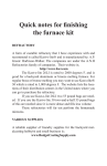
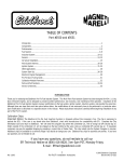
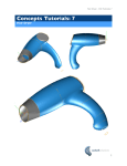
OPERATION &
MAINTENANCE MANUAL
MODERN ELECTRONICS & EQUIPMENT, INC.
AUTOMATIC PECAN CRACKER
Food Processing
Equipment and Machinery
Specializing in the Pecan
Industry
MODERN ELECTRONICS & EQUIPMENT, INC.
Mailing: PO Box 817,
Mansfield, Louisiana 71052
Located: 280 Independence Ave.,
Grand Cane, Louisiana 71032
www.me-equip.com
Phone: 318-872-4764
Fax: 318-872-4768
OPERATION & MAINTENANCE MANUAL
AUTOMATIC PECAN CRACKER
Instructions and helpful tips to
operate your Automatic Pecan
Cracker:
The cracker is shipped with the hopper bolted
in place. Be sure to check the hopper before
running the machine to remove any foreign
objects that may be in the hopper.
General Instructions
The Pecan Cracker should be oiled before
each use. An S.A.E. 20, or comparable light oil
is recommended throughout the unit. Oil all Red
Cups twice a day using 3-4 squirts of the oiler
provider with a new Cracker or using a hand
pump oiler. When maintaining the Pecan
Cracker, pay special attention to the Slide
Cover, C-6009. This part requires 6-8 squirts of
oil twice a day, so that the oil can get to the
moving parts of the Cracker Box. The Gray
Cups should be kept full at all times. This is to
make sure the Olite Bushings are replenished.
Part numbers and their location can be found
on Drawing C-6108 in the back of the manual.
These cleaning and re-lubrication instructions
should be repeated at intervals during the life
of the cracker. The frequency with which this
should be done depends to a large extent upon
the regularity with which the Cracking Box is
lubricated during service. With regular
lubrication the oil will aid in keeping the working
parts clean. During cleaning process it is good
practice to check for parts that may be worn or
need replacing. After crackers have been
operating for several seasons on long runs, it
may be more economical to return the entire
Cracking Box to Modern Electronics for a
complete reworking instead of replacing single
parts. It depends entirely on the overall
condition of the Cracking Box which method of
upkeep is best.
After crackers have been in operation for about
six months of daily operation, it is advisable that
the Cracking Box be removed from the cracker
for cleaning and re-lubrication to insure the
highest efficiency in Cracking Box operation.
To Set Crack Adjustment:
Loosen red Set Screw, #115, located behind the
Feed Chain and Hopper Bracket, C-8007-A.
Use screwdriver to turn Crack Adjustment
Screw located directly above Chain Adjustment
Cap, C-2030, and Discharge Chute at front of
machine. Turn clockwise for more crack,
counter-clockwise for less crack. After desired
adjustment is made, re-tighten Red Set Screw.
This adjustment should be made with the
Pecan Cracker running.
To Adjust Tension on Feed Chain Assembly:
Remove Inspection Plate, C-4020, located
immediately above the Chain Adjustment Cap,
C-2030. Insert a punch into one of the holes in
the Chain Adjustment Nut, C-2394. Move punch
toward the right to tighten chain, toward the left
to loosen chain. Care should be taken to tighten
chain only sufficiently to prevent slack. Too tight
adjustment on the chain will result in excessive
wear.
To Adjust Feed Chain Timing:
On new crackers Feed Chain Timing
Adjustment should be made within two to
three weeks after Pecan Cracker is placed in
operation. Inspection of Feed Chain Timing
Adjustment should then be made about twice a
month to make sure that the Nut Pockets are
clearing the Cracking Box Die properly.
Clearance between the Nut Pockets and the
Cracking Box Die, as it moves through the Nut
Pockets, must be maintained or Cracking Box
Parts may be damaged.
To check adjustment the Cracker Drive Pulley,
C-4507, should first be turned by hand until
the Cracking Box Die has moved to the
backside of the Nut Pocket. The Cracking Box
Die should not be in the Nut Pocket at this time.
Next, check to see if bottom of Nut Pocket is
1/16" to 3/32" below the Cracking Box Die. If
this clearance is correct, no further adjustments
is necessary. If clearance is not correct,
adjustment may be needed.
To adjust Feed Chain Timing, remove the
Inspection Plate, C-4020, and loosen the four
cap screws in Chain Adjustment Cap, C-2030.
Next, insert the Feed Chain Wrench, C-2141, in
MODERN ELECTRONICS &
EQUIPMENT, INC.
OUR SERVICES:
Modern Electronics and Equipment specializes in the fabrication of standard
and custom pecan shelling equipment. We have been serving the needs of
pecan shellers for more than 36 years. Our product line ranges from the
most standard elevators to rare pieces of equipment such as gas chambers.
Modern Electronics can also build equipment for any food processing
Since 1966, Modern Electronics and Equipment
operation. We are here to produce the proper equipment needed to make
has been serving the pecan industry nationwide
an operation run as smooth as possible. Our expert staff will work with you
by specializing in the fabrication of standard and
to not only populate your plant to your specifications, we also have the
custom pecan shelling equipment. Product lines
expertise and knowledge to fulfill your most daunting custom fabrication
consist of three different sizes of pecan shellers,
needs. We also manufacture all the replacement parts for products
pecan crackers, and a host of commercial and
previously owned by Meyer Machine Company.
non-commercial equipment used during the pecan
There is no parts order is too small to fulfill.
shelling process.
Page 1
MODERN ELECTRONICS & EQUIPMENT, INC.
NOTICE
Parts illustrated, and listed by number on the following pages, are for the latest model Modern Electronics & Equipment Pecan
Cracker. When ordering replacement parts, please give serial number of your Pecan Cracker, plus the following additional
information when ordering Cracking Box Yoke, C-2251 or Slide Plate, C-4165: Cracking Box Yoke, show diameter of pins, 1/2”,
9/16”, or 5/8”. Slide Plate, show thickness of bottom plate, 3/8” or 1/2”.
Please Note: Crackers after serial number 945 are considered “New Type”, shipped 12-1957.
slot of the Sprocket Idler Shaft, C-2074. Turn
Sprocket Idler Shaft in clockwise direction until
proper clearance is obtained; if necessary,
remove the four cap screws in the Chain
Adjustment Cap, C-2030, to advance to the
next Nut Pocket. NEVER TURN FEED CHAIN
COUNTER-CLOCKWISE TO MAKE FEED
CHAIN ADJUSTMENTS.
After proper clearance is obtained, tighten or
reinstall the four cap screws in the Chain
Adjustment Cap. Next, turn the Cracker by
hand through two complete cycles to make sure
the Cracking Box Die to Nut Pocket clearance
is correct. If clearance is correct, operate
machine.
To Change Nut Pockets:
Insert T-handled Wrench, C-2142, provided into
socket head screws which fasten Nut Pockets
to Feed Chain. Loosen screws, then remove
Nut Pockets and replace with desired size Nut
Pocket. In changing from one size set of Nut
Pockets to another size, it is also necessary to
remove the Tongue Casting** located at the
bottom of the Nut Hopper. Also remove the
Cracking Box Die (see next paragraph).
To remove Tongue Casting unscrew 3/8" cap
screw, then slide casting out of machine. After
the Nut Pockets have been changed, check the
clearance with the Cracking Box Die and if
necessary adjust as in preceding instructions.
** #11 and #13 Nut Pockets use Tongue
Casting C-2087 while #15 and #18 Nut Pockets
use Tongue Casting C-4460. Refer to Drawing
C-6108.
To Remove Cracking Box:
Unscrew Knockout Rod Bushing, C-2054, at the
rear of the machine and remove the Knockout
Rod, C-2420-B. Remove Cracking Box Slide
Cover, C-6009, unscrew Drive Stud, C-2287,
and lift the box out. After the Cracking Box has
been removed, it can be clamped in a vise,
taking care that clamping force is applied only
to the bottom plate of the box. The Die Rack
Spring may then be removed by removing
the Die Rack Spring Nut. Use the T-Handle
allen wrench supplied to hold pressure against
the Die Rack Spring Nut as you unscrew it.
Then ease the spring pressure off and remove
Die Rack Spring. Failure to use caution in
disassembling Cracking Box will cause bodily
harm.
Cracking box and all parts should be cleaned in
a suitable cleaning fluid, such as kerosene, and
dried. Care should be taken that the small hole
in the center of the Die Rack, C-4024, leading
to the Cracking Die is cleaned of all dust and
fine shell. This can be done by using a small
round brush which can be passed through the
hole.
In reassembling parts in the Cracking Box, care
should be taken that parts are replaced in their
proper working positions. Special attention
should also be given to the Pawl Spring
Adjustment Assembly, to make sure that Pawl
Spring Guide C-2311 is assembled in spring
and pawl alignment plug as shown below.
Parts should be re-lubricated as they are
reassembled in the Cracking Box. After
assembly of all parts, including Cracking Box
Cover, C-2180, the Cracking Box can be
replaced in the Cracker Frame and the
Connecting Arm, C-2281, connected to the
Drive Gear, C-4008, by inserting and tightening
the Drive Stud, C-2287. The Slide Cover can
then be replaced and reassembly is complete.
A properly lubricated Carrier Chain should ride
freely in a straight vertical line between
sprockets. If the Chain shows a tendency to
buckle, it is not receiving sufficient lubrication.
In such instance, additional oil should be
applied to the Carrier Chain until it runs free. If
this oil cup remains full, cup and tubing should
be immediately checked for possible clogging.
Insufficient lubrication will result in excessive
chain wear, binding of chain, and mis-alignment
of Nut Pockets with Cracking Box Die.
Removing Stationary Die Knockout Rod:
Refer to Drawing C-2440. Simply loosen Lock
Nut, C-2075, and the entire assembly can be
removed by unscrewing the Adjusting Screw.
Drawing C-2440
Drawing C-2728
Note A:
Pawl Alignment Spring
C-2412
C-2311
Pawl Spring Guide
C-2312
Pawl Alignment Plug
IMPORTANT:
When reassembling a Cracking Box, be sure
that Pawl Spring Guide, C-2311, Pawl
Alignment Spring, C-2412, and Pawl Alignment
Plug, C-2312, are assembled as shown to
insure proper operation.
To Change Cracking Box Die:
Remove Cracking Box Slide Cover Assembly,
C-6008-A, turn Drive Pulley, C-4507,
counter-clockwise until Cracking Box is at the
rear of machine, then place a punch against the
shoulder of back of the die and drive forward
and out. For correct combination of Nut
Pockets, Tongue Casting and Cracking Die,
refer to Drawing C-6108 on the back page of
the Manual.
Position the tapered end of the Cracking Box
Die into the end of the Cracking Box Die Rack,
C-4024, with clean-out hole in the die facing the
floor. Also the number stamped on the die
should face the installer. Turn the Drive Pulley,
C-4507, counter-clockwise until Cracking Box is
at the the front of the machine. Lift Inspection
Door, C-2036, insert brass rod through
Inspection Door opening until it contacts the
Cracking Box Die. Then use a hammer to drive
the Cracking Box Die into the Die Rack.
Carrier Chain Oil Cup:
The red cup, on the front of the Pecan Cracker,
MUST BE FILLED EACH DAY while the
Cracker is in operation. Periodic inspection of
the Carrier Chain should be made by
removing the Inspection Cover, C-4020, on the
front of the Feed Chain Plate, C-8008-A.
For proper crack, follow directions as outlined in
paragraph labeled "To Set Crack Adjustment".
Adjust Pecan Cracker just hard enough to crack
shell completely around all nuts.
Note B:
When reassembling chain, make sure that Nut
Pocket attachment holes are on bottom ends of
chain links on cracking side of unit. Refer to
Drawing C-6108.
Safety Guidelines:
The Modern Electronics Pecan Cracker comes
equipped with Protective Guards. DO NOT
OPERATE THIS MACHINE WITHOUT
PROTECTIVE GUARDS IN PLACE. Stop the
Pecan Cracker before performing maintenance
and before performing any other activities that
will require removal of Protective Guards. Stop
the Cracker before reaching inside the machine
with body parts (i.e. hands, fingers, etc.) or
tools. Failure to follow these guidelines can
result in severe injury or even death. Unless
otherwise specified, before operating this
machine, alert employees of safety guidelines.
As always, common sense and direct and clear
instruction will keep everyone safe.
Page 2
MODERN ELECTRONICS & EQUIPMENT, INC.
OPERATION & MAINTENANCE MANUAL
Cracker Box Parts
C-2108
C-2288-C
C-2057
C-2132
C-4024-B
C-2251-C
C-2104
C-2726-D
#188
C-2060
#194
#132
C-2134
Each Cracking Box Die
is inserted at the
Circled Area.
C-2180
C-2407
C-2454-D
C-2424
**C-4165-B
C-2423
C-2312
C-2412
C-2311
***C-6042
C-2421
C-2281
C--2455
C-2054
C-2420-B
C-2054
C-2057
C-2060
C-2076
C-2104
C-2108
C-2076
#130
C-2287
#119
#133
Cracking Box Rod Bushing
#18 Cracking Box Die
Crack Adjustment Spring Holder
Carriage Spring Plug
#13 Cracking Box Die
Square Yoke Bushing,
for ½" Slide Plate
C-2132
#11 Cracking Box Die
C-2134
#15 Cracking Box Die
C-2180
Cracking Box Cover with
(4) #132 Screws
C-2251-C Cracking Box Yoke
C-2281
Connecting Arm
*C-2282-A Rear Die Block without Tubes
and Holes
*C-2282-B Rear Die Blockwith Holes,
Machined with C-2422 & C-2283
*C-2283 Carriage Spring Holder
Welded to C-2282
*C-2284 Wrist Pin Block
*C-2285
*C-2286
C-2287
C-2288-C
C-2311
C-2312
C-2407
C-2412
*C-2420-A
Front Die Block
Adjustment Spring Guide
Drive Stud
Tapered Pawl 5/8”: A=½”, B=9/16”
Pawl Spring Guide
Pawl Alignment Plug
Crack Adjustment Spring
Pawl Spring
Cracking Box Knockout Rod
(Old) Goes thru Casting with
2 Cotter Keys- No Photo
C-2420-B Cracking Box Knockout Rod
(New) Has Bushing that
Screws in with Collar
C-2421
Wrist Pin, New Type
C-2423
Die Rack Spring Nut
C-2424
Die Rack Spring Guide
C-2454-D Die Rack Spring
C-2455
Carriage Spring (Slide Return)
C-2726-D Square Yoke Bushing,
State Size of Bore: ½”, 9/16”, 5/8”
C-4024-B Cracking Box Die Rack for
½” Slide Plate
**C-4165-B Slide Plate, Thickness
of Bottom Plate: ½"
***C-6042 Cracking Box Frame
*C-7776 Cracking Box Assembly
*C-7776-H Cracking Box Assembly,
Heat Treated
#130
3/8" x 7/8" SAE Allen Head
Dog Point Set Screw
#119 3/8" SAE Lock Nut
#132 ¼" x ¾" Flat Head or
Socket Cap Screws
#133 1/8" x ¾" Cotter Key
#188 #4 x 1-5/8" Taper Pin
#194 5/16” x 3/4” Dowel Pin
*#195 1/4” x 1/2” Socket Head Cap Screw
* Not Pictured
** C-4165-A Slide Plate, 3/8" NO LONGER AVAILABLE - Must Purchase Conversion Kit Consisting of: C-2108-A, C-2251-C, C-2288-C, C-2726-D, C-4024-B,
andC-4165-B.
*** C-6042 Cracking Box Frame is available as one part. It consists of C-2282 Rear Die Block, C-2283 Carriage Spring Holder, C-2284 Wrist Pin Block,
C-2285 Front Die Guide, and C-2286 Adjustment Spring Guide.
Page 3
MODERN ELECTRONICS & EQUIPMENT, INC.
OPERATION & MAINTENANCE MANUAL
Cracker Frame Parts
#161
#134
C-2105
#136
#135
#160
#159
#124
#137
C-2070
C-2068
#120
#189
C-2031
C-2030
C-2071
C-0001
#138
#139
#162
#163
C-2137
#148
C-2073-B
#144
C-2069
#154
C-4008
#153
#143
#151
#150
#141
C-2072-A
#193
#147
#154 #153
#152
C-4507
#155
#140
C-2098 C-2096
C-2099
#157
C-0001
C-2030
C-2031
C-2066
C-2068
C-2069
C-2070
C-2071
*C-2072
C-2072-A
*C-2072-B
*C-2073-A
C-2073-B
*
C-2262
C-2411
Cracker Frame (with bushings)
Chain Adjustment Cap with
#189 Key
Sprocket Adjustment Bearing
with #189 Key
Cracker Drive Shaft
Lower Chain Sprocket,
20 Tooth with #189 Key
Drive Shaft Gear,
30 Tooth with #147 Key
Sprocket Shaft Gear,
30 Tooth with #120 Taper Pin
Sprocket Drive Shaft
with #120 Taper Pin
Pinion Shaft Only
with #193 Taper Pin
Pinion Gear and Shaft Assembly
Pinion Gear Only with
#193 Taper Pin
Feed Chain Drive Shaft with
#148 Taper Pin (Old 18-7/8")
Feed Chain Drive Shaft with
#148 Taper Pin (New 19-5/8")
C-2066
C-2096
C-2098
C-2099
C-2105
C-2137
C-2262
C-2411
C-4008
C-4507
#120
#124
#134
#135
#136
#137
#138
#139
#140
#141
#142
C-0001
#142
Eccentric Washer
Vibrator Eccentric
Vibrator Shaft with C-2097
Connector
Stationary Die
Bronze Worm Gear-Hub out or
in with #148 Taper Pin
Drive Shaft Pin
Steel Worm, Hardened & Polished
Drive Gear
Drive Pulley
#7 x 2" Taper Pin
Oil Pipe, 1-1/4" Long
3/8" x 3/8" Allen Head Set Screw
1" x 1-1/4" x 2-1/4" Bronze Bushing
1-1/2" x 1-3/4" x 1-1/2" Bronze Bushing
5/8" Hex Nut
7/16" x 5/8" x ¾" Bronze Bushing
1-1/4" x 1" x 2-1/2" Bronze Bushing
3/4" x 1" x 2" Bronze Bushing
3/4" x 1" x 1-3/4" Bronze Bushing
7/8" x 1-1/8" x 1-3/4" Bronze Bushing
#143
#144
#147
#148
#150
#151
#152
#153
#154
#155
#157
#159
#160
#161
#162
#163
#189
#193
Not Pictured
Page 4
MODERN ELECTRONICS & EQUIPMENT, INC.
7/8" x 1-1/8" x 2" Bronze Bushing
1" x 1-1/4" x 3" Bronze Bushing
¼" x ¼" x 1-3/4" Key
#7 x 1-3/4" Taper Pin
7/16" x 1" x 3/16" Washer
7/16" x 1-1/4" Hex Head Cap Screws
3/8" x 3/8" Allen Head Set Screw
3/8" x 5/8" Square Head Set Screw
3/8" x ½" Square Head Set Screw
#19 x 3/16" x 1-1/4" Woodruff Key
3/8" Acorn Nut
Oil Pipe, 3-1/4" Long
Oil Pipe, 4-1/4" Long
Oil Pipe, 8-1/2" Long
GIts Oil Cup, #325
Plug
¼" x 1-1/4" Key
#4 x 1-1/4" Taper Pin
OPERATION & MAINTENANCE MANUAL
Cracker Drive Parts
C-2403
#101
#108
#107
#118
C-2067
C-4128-A
C-2582
C-2395
C-2141
C-4025
#103
#123
C-2577,
C-2142
C-2409
#109
#105
#102
#106
#128
C-2074
#104-A
C-2293
#145
C-6036-A
#146
#110
#119
C-2075
C-4021
#129
#113
#115
#117
#114
#116
#194
C-4652
C-2037
C-2037
Left
Right
C-2049
C-2394 C-2410
C-2944
C-0001
C-2050
C-2032
C-2085
#112
C-2027
C-2032
C-2037
C-2037
C-2049
C-2050
C-2067
C-2074
C-2075
C-2085
C-2086
C-2087
C-2141
C-2142
C-2293
C-2394
C-2395
C-2403
C-2409
C-2410
C-2577
C-2582
*
C-2086
C-2087
C-2027
#111
C-4460
#13 Nut Pocket
#18 Nut Pocket
Chain Bar, Right Hand
Chain Bar, Left Hand
Chain Adjustment Pin
Crack Adjustment Screw
Top Chain Sprocket, 20 Teeth
with #120 Taper Pin
Sprocket Idler Shaft
with #120 Taper Pin
Knockout Rod Screw and Nut
#11 Nut Pockets
#15 Nut Pockets
#11, #13 Tongue Casting
Feed Chain Wrench
Nut Pocket Wrench
Stationary Die Knockout Rod Tip
Chain Adjustment Nut
Stationary Die Knockout Rod Sleeve
Motor Bracket
Stationary Die Knockout Rod Spring
Chain Yoke Washer
Die Rack Spring Wrench
Vertical-Horizontal Brace Plate
#120
#121
C-2944 Chain Yoke Washer
C-4021 Lower Chain Bracket
C-4025 Lock Pin
C-4128-A Stationary Die Knockout Rod
*C-4128-B Stationary Die Knockout Rod
Assembly
C-4460 #15, #18 Tongue Casting
C-4652 Feed Chain Assembly without
Nut Pockets
C-6036-A Chain Yoke Assembly with (2) #118
#101
#102
#103
*#104
1/3 HP Master Motor, 110-220 Volt
Motor Pulley with #107
Motor Switch Box
Motor Switch & Circuit Breaker
Assembly
#104-A Toggle Switch
#105 8 Amp Fuse
*#105-A 10 Amp Circuit Breaker
#106 Motor Cord Clamp
#107 Motor Pulley Key
#108 V Belt
#109
Motor Cord (14/3 Wire)
#110 Motor Cord Male Plug (3 Prong)
#122
#111
#112
#113
#114
#115
#116
#117
#118
#119
#120
#121
#122
#123
#124
#125
#128
#129
#145
#146
#191
#192
#194
#124
#125
#191
#192
5/16" x 1-1/2" Socket Head Cap Screw
3/8" x 1-1/2" Hex Cap Screw
3/8" x 2" Hex Head Cap Screw
3/8" x 1" Hex Head Cap Screw
3/8" x 1½" Square Head Set Screw
3/8" x ½" Square Head Set Screw
5/16" x 1½" Dowel Pin
1" x 1-1/4" x 1-3/4" Bronze Bushing
3/8" SAE Lock Nut
#7 x 2" Taper Pin
Oil Pipe, 4-1/4" Long
Street Ell - 1/8" Pipe
Oil Pipe, 2-1/4" Long
Oil Pipe, 1-1/4" Long
Gits Oiler 5/16”, #325
Chain Section
Chain Pin Link
3/8” x 1” Hex Head Cap Screws
3/8” Lock Washer
4" Oil Pipe
45° Elbow
5/16" x ¾" Dowel Pin
Not Pictured
Page 5
MODERN ELECTRONICS & EQUIPMENT, INC.
OPERATION & MAINTENANCE MANUAL
Cracker Cover Parts
#125
#171
#179
#165
#172
#180
#166
#173
#181
#167
#174
#183
#169
#177
#170
#178
#186
C-4023
C-4522-B
#187
C-6007
C-4038
C-4039
C-4020
C-2036
C-0001
C-2400
C-8007-A
C-8008-A
#184
#182
C-8009
C-2943
C-2942
C-6009
C-6008
C-9705
C-6020-B
C-2036 Inspection Door
C-2400 Inspection Door Weight
C-2942 Left Hand Nut Pocket Guide
C-2943 Right Hand Nut Pocket Guide
C-4020 Inspection Plate
C-4023 Name Plate
C-4038 Nut Guide Strip, Right
C-4039 Nut Guide Strip, Left
C-4522-B Worm Gear Guard, New Type
C-6007 Rear Leg
C-6008 Drive Gear Cover (New Only)
*C-6008-A Drive Gear Cover/Slide Cover
Assembly
C-6009 Slide Cover with (2) #177
C-6020
Sheet Metal Belt Guard
C-8007-A Feed Chain and Hooper Bracket
*
#176
C-9704
C-8008-A
C-8009
C-9704
C-9705
#125
#165
#166
#167
#169
#170
#171
#172
#173
#174
Feed Chain Plate
Front Leg
Hopper Base
Hopper Top
Gits Oil Cup, #325
5/16" x 1-1/4" Round Head Screw
3/8" x 1" Hex Head Cap Screw
3/8" x 1" Fillister Head Screw
3/8" x 2" Hex Head Cap Screw
5/16" x 5/8" Round Head
Machine Screw
3/8" x 1" Hex Head Cap Screw
5/16" x ¾" Dowel Pin
Gits Oil Cup, #325
3/8" x ¾" Round Head Bolt
#176
#177
#178
#179
#180
#181
#182
#183
#184
*#185
#186
#187
Not Pictured
Page 6
MODERN ELECTRONICS & EQUIPMENT, INC.
Gits Oiler with Copper Tubing
#10 x 5/8” Rivets
3/8" x ¾" Hex Head Cap Screw
¼" x 5/8" Flat Head Screw
5/16" x ¾" Hex Head Cap Screw
¼" x ½" Flat Head Screw
Chain Oiler with Copper Tubing and
40° or 45° Elbow
1/16" x ½" Cotter Pin
3/16" x 1-1/8" Dowel Pin
1/16" Flat Washer
¼" x 5/8" Flat Head Screw
¼" x ½" Flat Head Screw
C-2085
C-2027
#11
#13
C-4248
C-4249
C-4460
C-4460
C-2134
C-2057
C-2066
C-2032
#15
#18
C-4250
C-4251
C-2423
C-2287
C-0001
C-2099
C-2420
#117
C-2072
C-2726
C-2054
C-2137
C-6036
C-2074
C-4008
C-6042
C-2281
C-2288
C-2312
C-2180-A
C-2283
C-2060
2455
C-2410
C-2394
C-4021
Tongue
Casting
C-2424
C-2076
C-2049
Drawing C-6108
(Refer to
Table C-1)
C-2395
C-2108
C-2251-C
C-2050
C-2068
C-2031
C-2030
C-4165-A
C-2454
C-2311
C-2407
C-2059
C-6042
C-2071
C-2409
C-4128
C-2293
C-4024
C-2105
Cracking Die
(Refer to Table C-1)
Nut Pocket
C-2075
(Refer to Table C-1)
C-2412
C-2422
C-2421
#132
(Plug in front
of Spring)
Phone: 318-872-4764
Fax: 318-872-4768
C-2132
C-2104
www.me-equip.com
C-2073
C-2067
C-2087
C-2087
C-2097
C-2096
C-2066
C-2411
C-2098
C-2037
Nut Pocket
Machining
Located: 280 Independence Ave.,
Grand Cane, Louisiana 71032
C-2141
Pecan
Size
Mailing: PO Box 817,
Mansfield, Louisiana 71052
C-2142,
C-2577
Nut
Pocket
MODERN ELECTRONICS & EQUIPMENT, INC.
TABLE C-1
Tongue Cracking
Die
Casting