1
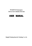
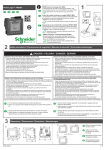
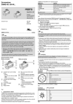
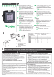
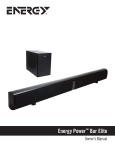
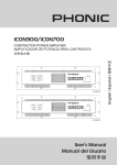
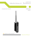
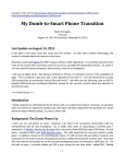
WS420 ARD
WS420 Elevator
Emergency Power Device
USER MANUA
MANUALL
Shanghai Wenshang Innovative Technology Co., Ltd.
0
Sh an g hai Wens h an g
WS420 ARD
Notice
☆
Dear customer, at the outset we want to thank you for choosing our company’s
product!
To help you install and use the product correctly, as well as to
guarantee the safety of elevator equipment and this product, please carefully
read this User’s Manual before you start to install and commission this product.
☆
Please carefully check the model number and parameters (provided by the buyer
on purchasing) on the nameplate, which is pasted on the rear panel of this ARD’s
host machine, as well as the same contents of the elevator.
If any mismatch is
found, please do not install this device, let alone power on it to test. Please
contact the service department of our company immediately and discuss with our
service staff for a solution. The service telephone numbers are: 02164802098/13/16/17
64802098/13/16/17, 64802658
High voltage exists in the cabinet. If the cover is opened for debugging,
please do not touch the high-voltage part.
★
Six months after the production date, if the product has not been put into normal
operation yet (e.g. the box is not opened or although the product is installed and
debugged but the elevator is not started for using), please be sure to charge the
storage battery as the following method:
Open the rear cover of the ARD
ARD’’s host machine, take out power wires and
cables, and connect them tightly with the corresponding terminals on the
battery box (0V, 24V, 48V), and then connect the device to 3-phase 380v
power supply line (L1/L2/L3) and zero line (N)
(N),, switch the power switch on
the front panel of the device to the ON position, charge the battery for 24
hours.
☆ We keep the right to improve and modify the product and this user’s manual.
The user’s manual is subject to change without notice.
1
Sh an g hai Wens h an g
WS420 ARD
Content
1.
Summarization . . . . . . . . . . . . . . . . . . . . . .
3
2.
Operation principle . . . . . . . . . . . . . . . . . . . .
.5
3.
Installation and wiring . . . . . . . . . . . . . . . . . .
.7
4.
Commission procedure . . . . . . . . . . . . . . . . . .
14
5.
Maintenance notice . . . . . . . . . . . . . . . . . . .
19
6.
Maintenance Guide . . . . . . . . . . . . . . . . . . . .
. . .20
7.
Package List . . . . . . . . . . . . . . . . . . .. . .
.21
8.
Warranty Card . . . . . . . . . . . . . . . . . . . . . .
.22
9.
Certification . . . . . . . . . . . . . . . . . . . . . .
23
2
Sh an g hai Wens h an g
WS420 ARD
Summarization
1.
Summary
The follows
WS420 series of elevator Emergency Power Device (EPD) or Automatic Rescue Device (ARD), (The
are abbreviated as ARD
ARD) are a same type of safety equipment aiming at the emergent stop of the elevator which
is caused by power failure or power malfunction.
In the emergent rescue, the equipment is powered by storage
battery. The energy stored in the battery is reversed into the electricity needed by the elevator. The elevator will
be started and the cage will be pulled to the near floor, then the car door and landing door will be opened and the
passenger can leave safely without being stuck in the elevator.
For H multifunction type and HB smart type,
except being used for power failure emergency rescue, they can also provide automatic emergency rescue and
play comforting voice to make the passenger not be panicky when malfunction occurs to the electric controlling
system of the elevator.
The smart type can also automatically call and notify service personnel for any electric
or mechanic fault of the elevator.
Product model
1)Product
WS 420 □ □□ □□ - □
Wenshang Company
Code of emergency equipment
E Export model
Additional
code
L Extra-long model
T One-drive-two model
G Basic model
Function:
S Standard model
code
H Multifunction model
HB Smart model
Current parameter: Rated current of traction machine
AC,WJ No machine room
Elevator:D DC, WC No gear
code Y Hydraulic, P Special
FB Explosion Protected
2) Functions and other requirements
The basic functions and optional requirements of emergency equipment are listed in table 1.
3
Sh an g hai Wens h an g
WS420 ARD
Function
Series
Power Failure
Emergency
Fault
Emergency
Voice
Comfort
G Basic Series
○
S Standard Series
○
H Multifunction
○
○
○
HB Smart Series
○
○
○
Wire-less
Call
○
Export
Long
distance
Special
△
△
△
△
△
△
△
△
△
Note:“ ○ ” means basic function: “ △ ”means optional function for the customer’s choosing
Table 1
Functions of emergency equipment
3) Main technical parameters
(1) Input voltage: 3Ф380 V (special voltage requirement shall be given a clear indication in the order)
(2) Storage battery set: 12 V /(12AH - 33 AH)× 4 (the capacity of real equipment is based on the
specification of the order)
(3) The maximum driving power of elevator can be customized: ≤ 70KW (the capacity of real equipment is
based on the specification of the order)
Summarization
4) Working environment
(1) Environment temperature: -0℃ to 40℃
(2) Relative humidity: < 95%, without dew;
(3) No explosive or corrosive harmful gas or dust exists in the air.
5) Configuration structure
According to the installation method, the emergency equipments are divided into two types: with machine room
and without machine room. And the configuration structures of these two types are shown like picture 1A
and picture 1B.
Picture 1A
Configuration structure of elevator emergency equipment with machine room
4
Sh an g hai Wens h an g
WS420 ARD
图A 立式整体安装
5
1
6
12
图B 水平分体安装
2
215
7
3
10
11
8
(深500)
390
200
9
4
背面
正面
1.主机
2.电源(工作)开关
3.商标
4.蓄电池
5.电源指示灯(红)
6.应急运行指示灯(绿)
Standing integral installation
7.铭牌
8.接线口盖板
9.接线柱(蓄电池输出)
10.控制电缆插座B1
11.控制电缆插座B2
12.控制电缆插座B3
Horizontal split installation
1. Host machine 2. Power (work) switch 3. Label 4. Storage battery 5. Power supply indication lamp (red)
6. Emergent operation indicating lamp (green) 7. Nameplate 8. Cover of connection open 9. Terminal
Operation Principle
post (output of storage battery) 10/11/12. Controlling cable socket B1/B2/B3
Picture 1B
Configuration structure of elevator emergency equipment without machine room
front view
1. Host machine
2. Cover
side view
rear view
3. Power supply switch
5
4. Handle
5. Panel
6. Socket B1 of controlling
Sh an g hai Wens h an g
WS420 ARD
cable
7. Socket B2 of controlling cable 8. Socket B3 of power supply cable 9. Motor output terminal TD
2. Work Principle
Out/input power
face to the controlling
supply detection
controlling system
Charging loop
Door machine
system of the elevator
PLC controlling system
Storage battery set
Door
DC convertor
Current sensor
Brake
3-phase reversing loop
Traction
Picture 2. ARD block diagram
Operation Principle
1) Power supply detecting
The power supply detecting board of the emergency equipment K11 inspects the status of the input three phase
power supply all the time.
If the power supply is in normal status, the storage battery set of the equipment is
automatically floating charged by charging loop and be kept at the rated work voltage.
The charging loop has
over-charge, over-current and short-circuit protecting functions. If the power of the loop is off, a power off signal
will be sent to the controlling system and the system will make emergent processing.
2) Emergent operation
The controlling system of the ARD will immediately detect the status of the elevator and automatically start the
emergent rescue when the elevator runs into a power failure (for type G and S) or a controlling system fault of the
elevator (for type H and HB). First the power supply contactor K12 is pulled in, the connection between the R, S,
T three-phrase controlling power supply and the inputting terminals R0, S0, T0 of the controlling power supply in
the elevator’s controlling cabinet is shut off by the normally-closed contacts.
relay K3 closes.
Then the safety, lock and
The normally opened contact of
overhaul loops of the elevator are detected, and the door area
sensor is powered on, the near floor signal is also detected.
If the loops are in normal status the converter will be
switched on to power on the door machine controlling system.
The relay K14 of the ARD is pulled in (see
picture 8 for AC door machine, see picture 9 for DC door machine, and see picture 10 for variable frequency door
machine), the door-motor MD gets the voltage it needs, and opens the car door and landing door synchronously.
If the cage is not at the near floor position, the normally opened contacts of brake relay K7 and K8 close (see
picture 11), the DC converter supplies the brake loop to open the brake.
The voltage outputted from 3-phase
reversing loop goes through K10’s normally opened contactor (which is closed now) to power on the traction
machine, which pulls the cage to run at a certain direction.
The cage moves to the near floor position and stops.
The 3-phase reversing voltage stops outputting, the brake closes. After the car door and cage door are opened, the
6
Sh an g hai Wens h an g
WS420 ARD
contacts of contactors and relays of the ARD mentioned above resume to the status before the emergent operation.
The connection between 3-phase AC power supply and the controlling system of the elevator is resumed and the
emergent operation is ended, the power supply of the ARD is automatically shut off.
3) Safety lock
If the controlling system of the ARD judges the stopping of the elevator is due to the fault of safety loop or door
lock loop, the equipment will not start the emergent operation according to the requirements of Safety Norm for the
operation of elevator. After the emergent operation is started, the ARD still detects the signal from elevator safety
loop and door lock loop all the time.
Once a protecting signal is generated, the emergent operation is stopped
immediately to assure the safety of the passengers and the elevator equipment. At the mean time the ARD is also
detecting the overhaul loop of the elevator’s controlling system all the time.
When the service personnel are
examining the elevator, the ARD is automatically locked and will not be put into emergent operation if only the
examining switch is pressed down.
4) After the emergent operation
Installation
Wiringis
After the emergent operation, the connection between the equipment and the controlling
system ofand
the elevator
shut off and the ARD is at the isolated stand-by status without any affection to the operating of the elevator.
The elevator can normally operate if only the power from the 3-phase AC power supply is resumed. The charging
loop of the ARD automatically charges the storage battery set again.
3.
Installing Connection
The ARD is easy to install. If there is a machine room it can be installed beside the elevator controlling cabinet;
if there is not a machine room, it can also be fixed beside the controlling cabinet with the accessory installation
rack. Before starting connection the personnel shall first open the shell of the ARD’s host machine and take out
the controlling cables and relays, as well as other accessories. The general connection between the ARD and the
controlling system of the elevator is shown in picture 5.
This user’s manual is a unified general version to match all types of elevators produced inside/outside China
instead of a special version for a certain elevator. When you get this manual, please do not be hurry to connect
those wires. We suggest you carefully compare the drawings in this manual with corresponding drawings of the
elevator’s controlling system, find out the corresponding signal or terminal numbers needed for connecting with
the ARD on the drawings and make marks. A signal-comparison-table (for signals related with the ARD and the
elevator’s controlling cabinet) is strongly recommended for the using of connection. If other drawings or
supplementary text illustrations are appended to the manual, it is due to the special requirements of your elevator.
Please take these appended drawings and supplementary text illustrations as the criterion for installation and
debugging.
1) Connection of main power supply
For most elevators, the terminals B3-1, 2, 3, 4 (R, S, T, N) shall be connected to the R, S, T and N terminals of the
3-phase power supply of the elevator’s controlling cabinet (Note: Be careful not to connect the zero line N to the
7
Sh an g hai Wens h an g
WS420 ARD
fire line, other wise the equipment will be burnt.
See picture 3 and picture 5), and then the ~380V inputting
terminal of the elevator’s controlling power supply transformer shall be disassembled and connected to the B3-5,
6 terminals of the ARD.
That is, make the ARD, the 3-phase AC power supply and the 380V controlling
transformer a series connection, and then connect U, V, W terminals of the ARD to the 3-phase output power
supply terminals U, V and W between the controlling cabinet and the traction in a parallel connection with
4~6mm2 cables. (The wires, backup-traveling cables shall be prepared by the user)
2) Connection of storage battery set
The connection between the ARD’s host machine and the storage battery set is prepared at the host machine end.
The user needs to take out the connecting cable and connect them to corresponding terminal posts of the battery
set separately (see picture 4).
The red post is anode and the black one is cathode. (For ARD for elevators
Installation and Wiring
without machine room, the connection shall be prepared.)
主动力接线
主电源变压器
POWER LINE 3ph 380v
电梯控制器
KM4
KM1
R
TU
L1
2
3
4
5
6
U1
VVVF
S
TV
L2
1
*部分电梯有
TW
T
L3
V1
W1
U
1
2
3
4
5
6
V
W
VF主电源
K10
TU
1
TV
3
4
5
6
TW
1
9
电梯控制
变压器
控制柜内封
星接触器
R2
R1
9
K12
11
3
R4
R3 V
10
4
12
如曳引机为无齿轮永磁同步电
机且有封星时增加此接线部分
N
Picture 3 Connection of power supply
电梯控制变压器:elevator controlling transformer 主动力接线:main power supply connection
主电源变压器:main power supply transformer 电梯控制器:elevator controller
部分电梯有:a part of elevators have 主电源: main power supply
控制柜内封星接触器:封星 contactor in the controlling cabinet
如曳引机为无齿轮永磁同步电机且有封星时增加的接线部分: this part shall be added if the traction is PM
synchronous motor without gear but with 封星
3) Connection to the controlling cable socket B1
应急装置
B1 is the special cable socket of controlling cables leading to the safety, door lock and
overhauling loops in the well hole. Before starting the connection of this portion, the
terminals of signal cables in the elevator's controlling cabinet leading to those three loops
in the well hole mentioned above shall be found out first.
If terminals or terminal posts
are prepared by the elevator’s manufacturer, then disassemble the original terminals and
make marks following the sequence numbers of B1 socket terminals and connection
illustration shown in table 2 and table 3. Then use the accessory 12-pin controlling cable
8
红
48V
红
24V
黑
0V
电池箱
Sh an g hai Wens h an g
WS420 ARD
to make connection (see picture 5 and picture 6).
Take the safety loop as an example, the detailed connection shall be like the
Picture 4 Connection of battery
following: B1-1 and B1-2 shall be connected to the two terminals at the side of the
safety loop in the well hole, and B1-3 and B1-4 shall be connected to the two
3
2
1
terminals at the side of the elevator’s controlling cabinet. The connection of
6
5
4
door lock and overhauling loops are similar to the connection of safety loop. If
9
8
7
the elevator manufacturer does not Take the safety loop as an example, the detailed
12
11
10
connection shall be like the following: B1-1 and B1-2 shall be connected to the two
terminals at the side of the safety loop in the well hole, and B1-3 and B1-4 shall
Table 2 Sequence numbers
be connected to the two terminals at the side of the elevator’s controlling cabinet.
The connection of door lock and overhauling loops are similar to the connection of safety loop.
If the elevator
manufacturer does not prepare the terminals, the six signal cables of those three loops leading to the well hole
9
Sh an g hai Wens h an g
WS420 ARD
Installation and Wiring
3-phase
三相输入电源
input power
12-pin
supply
总
General
Controlling
电
Power 源
Supply 开
关
cable芯控
制电缆
Switch
插头
插头
插头
12-pin
Safety
Controlling
芯
Loop
安
全
回
路
cable控制
电缆
Door
门
锁
回
路
Lock
Elevator
Loop
controlling
WS420 Emergent
插座
Equipment插座
cabinet
插座
电梯 Overhauling
控制柜Loop
应急装置
检
修
回
路
接触器
抱闸
电压
控制电源
Door
machine
3-
phase power
supply
Brake
门机三
相电源
制动器
Relay
Traction
Door motor
Cage
继电器
轿厢
曳引机
门电机
Picture 5 General drawing of ARD’s connection
接触器 contactor
抱闸电压 brake voltage
控制电源:controlling power supply
插头: plug
Note: If the traction is PM synchronous motor without gear but with 封星, those two lines at the front end
of the 封星 contactor in the elevator’s controlling cabinet shall be connected to B3-9 and 10 (refer to picture 3
and table 7).
Otherwise this equipment will be damaged.
10
Sh an g hai Wens h an g
Installation and Wiring
WS420 ARD
shall be cut off in the controlling cabinet and marks shall be made, and then the connection shall be made
separately. After the B1 has been connected, make a mark on the B1 plug and plug it into the B1 socket.
4) Connection to the controlling cable socket B2
B2 is the special cable leading to door area sensor and door machine.
(1) Please follow the signal definitions and connection illustrations of table 4 (variable frequency door
machine), table 5 (DC door machine) or table 6 (AC door machine).
No.
Code
Definition
No.
B1-1
SAFI1
B1-5
DLI1
B1-2
SAFI2
Safety loop
input
B1-6
DLI2
B1-3
SAFO1
Safety loop
output
B1-7
DLO1
B1-8
DLO2
B1-4
SAFO2
Code
Definition
Door lock loop
input
Door lock loop
output
No.
Code
B1-9
INSI1
B1-10
INSI2
B1-11
INSO1
B1-12
INSO2
Definition
Overhauling
loop input
Overhauling
loop output
Table 3 Signal definitions of socket B1
STOP
B1 -3
9
1
电
梯
controlling
控
cabinet
制
柜
Elevator
B1-7
SMH1
11
9
安全回路
B1- 8
4
12
门锁回路
SAL
SAT
B1- 10
( IN CAR) 检 修 回 路
电
梯
controlling
控
cabinet
制
柜
Elevator
K1
B1- 6
K2
10
( INS LOOP)
B1- 4
2
10
SMC
B1 -9
K2
1
SAFE LOOP
SMHN
DOOR LOCK LOOP
SAP
B1-11
(ON CAR)
K1
B1- 2
SSG
(IN CAR)
B1 -5
K1
3
STOP
B1 -1
K1
B1- 12
2
( CAR TOP)
Picture 6. Circuit in the well hole
Use B2 cable, disassemble the +24V or 48V line which leads from the controlling cabinet to the door area sensor
and connect the line to B2-2, and then connect B2-1 to one end of the controlling cabinet (see picture 5 and
picture 7).
The B2-3 shall be connected to 0V terminal.
Disassemble the upper near floor signal line LU from
the terminal, if there is not a terminal, cut off the line here and separate it into LUI and LUO, marks shall also be
made.
At the controlling cabinet side the LUO shall be connected with B2-6 line, at the well hole side the LUI
shall be connected with B2-5.
The connection of down near floor is the same like the connection of the upper
near floor, at the side of controlling cabinet the LDO is connected with B2-8, and at the well hole side the LDI is
connected with B2-7.
(2) The connection from B2 to the door machine will borrow the backup controlling cables from the
machine room to the well hole which are leaded to the top of the cage (5 cables to the serial communication door
machine, 6 cables to the DC adjustable door machine), and the accessory isolating transforming relay K14 shall
11
Sh an g hai Wens h an g
Installation and Wiring
WS420 ARD
be installed at a proper position on the top of the cage near the door machine.
For serial communication door machine or AC 380V door machine, (K14 shall be added), the door driving motor
MD 3-phase power supply lines shall be disassembled from the U, V and W terminals on the junction box on the
motor side (see picture 8), and connect them to terminal 1, terminal 2 and terminal 3 of K14’s normally-closed
contacts. Then MD's U, V and W shall be connected to K14’s 9, 10 and 11 with wires in the same specification.
The lines B2-9, B2-10 and B2-11 from the backup cables are separately connected to terminal 5, 6 and 7 of
K14’s N.O contacts.
B2-4 and B2-3 are separately connected to terminal 13 and terminal 14 on K14’s loop.
For DC door machine, the line which used to connect to the “+” end of the motor MD’s stator winding power
supply shall be disassembled, and be connected to No. 3 terminal of K14’s normally closed contact.
The line
used to connect to “-“ end shall be disassembled and connected to No. 4 terminal of K14’s N.C contact.
The
“+” end of the stator winding shall be connected to No. 11 terminal of K14, and the “-” end shall be connected to
No. 12 terminal of K14. Then disassemble the lines at the "+” end and “-“ end of the field winding LM, connect
them to terminal 1 and 2 of K14’s N.C contact. LM’s “+“ end is connected to K14’s No. 9 terminal, and the ““ end is connected to No. 10 terminal. Lines B2-9 and B2-10 from the backup cables are separately connected to
terminal 7 and 8 of K14’s normally-opened contact, and B2-10 and B2-11 are separately connected to terminal 5
and 6 of K14’s normally-opened contact, B2-4 and 3 are separately connected to terminal 13 and 14 of K14’s
normally-opened contact.
For frequency variable door machine (see picture 10), the power supply line “L” (fire line) from the controlling
cabinet to the door machine’s transducer shall be disassembled and be connected to B3-8, and the end at the
cabinet shall be connected to B3-7. B2-12 (zero line) shall be connected to the power supply line “N” to the door
machine’s transducer in parallel, B2-9 shall be connected to the COM end of the door machines open/close door
signal line, B2-10 shall be connected to the open door (DO) end of the door machine in parallel, also the B2-11
shall be connected to the close door (DC) end of the door machine in parallel. (If the power supply to the door
machine’s transducer is at the top of the cage, a relay shall be added at the top of the cage for isolation).
5) Connection to the controlling cable socket B3
B3 is the special cable used for isolating the controlling power supply, the 封星 , it is also the cable supplies
power for the brake. The third accessory controlling cable is used as B3 (see picture 3, picture 5 and table 7).
When making connection the controlling power supply terminals S0 and T0 connecting to the elevator’s
controlling cabinet shall first be disassemble from the S and T terminals of controlling cabinet’s controlling
transformer, and connect them to No. 5 line and No. 6 line (R0, S0) of cable B3 which is located at the rear of the
ARD, ant the other phase R shall be connected with B3-1, that is, make the ARD and the controlling transformer’s
AC power supply a series connection.
parallel.
Those two 封 星
The No. 4 line of B3 shall be connected to the zero line of the input in
relay lines (U1 and V1) on the traction in the controlling cabinet shall be
disassembled and connected to No. 9 and No. 10 terminals of B3 (see picture 4).
(Only for synchronous motor
with 封星)
12
Sh an g hai Wens h an g
WS420 ARD
Installation and Wiring
Door area
sensor
门区传感器
门区传感器
Picture 7. Connection of door area sensor
Picture 8. serial communication or AC 380V door machine
Door machine
Power Supply
Door machine transducer
Picture 9. Connection of DC door machine
Picture 10. Connection of VVVF door machine
Brake Loop
The brake voltage takes the parameter
as criteria (DC 220/DC110/AC220 etc. )
Picture 11 Connection of brake loop
13
Sh an g hai Wens h an g
WS420 ARD
Tabl
e 4.
No.
Sign
B2-1
al
defi
niti
Code
Definition
No.
Code
24VI
24V/48 in
B2-5
LUI
B2-2
24VO
24V/48 out
B2-6
LUO
B2-3
0VO
0V end
B2-7
LDI
B2-4
K14+
K14 loop +
B2-8
LDO
Definition
on
No.
Code
Upper near
floor in
Upper near
floor out
Lower near
floor in
B2-9
COM
B2-10
KDO
B2-11
KDC
Lower near
floor out
B2-12
NO
Definition
Open/close
door public
Open/close
door signal
Close door
signal
Door machine
power supply
0V
of B2 socket (frequency variable door machine)
No.
Code
Definition
No.
Code
B2-1
24VI
24V/48V in
B2-5
LUI
B2-2
24VO
24V/48V
out
B2-6
LUO
B2-3
0VO
0V end
B2-7
LDI
B2-4
K14+
K14 loop +
B2-8
LDO
Definition
Upper near
floor in
Upper near
floor out
Lower near
floor in
Lower near
floor out
No.
Code
B2-9
MD+
B2-10
MD-
B2-11
LM+
B2-12
LM-
Definition
Door armature
+
Door armature
Door excitation
+
Door excitation
-
Table 5. Signal definition of B2 socket (DC door machine)
No.
Code
Definition
No.
Code
B2-1
24VI
24V/48V in
B2-5
LUI
B2-2
24VO
24V/48V out
B2-6
LUO
B2-3
0VO
0V end
B2-7
LDI
B2-4
K14+
K14 loop +
B2-8
LDO
Definition
Upper near
floor in
Upper near
floor out
Lower near
floor in
Lower near
floor out
No.
Code
B2-9
Um
B2-10
Vm
B2-11
Wm
Definition
Door machine
U
Door machine
V
Door machine
W
B2-12
Table 6. Signal definition of B2 socket (serial communication or AC380V door machine)
No.
Code
B3-1
RI
B3-2
SI
B3-3
TI
B3-4
N
Definition
No.
Power supply
in
Power supply
in
Power supply
in
Zero line
Code
Definition
B3-5
R0
R0
B3-6
S0
S0
B3-7
LI
B3-8
LO
Door power
supply in
Door power
supply out
No.
Code
Definition
B3-9
U1
封 星
B3-10
V1
封 星
B3-11
BK+
Brake loop+
B3-12
BK-
Brake loop-
Table 7. Signal definition of B3 socket
14
Sh an g hai Wens h an g
WS420 ARD
Commission Procedure
5) Connection to the controlling cable socket B3
B3 is the special cable used for isolating the controlling power supply, the 封星 , it is also the cable supplies
power for the brake. The third accessory controlling cable is used as B3 (see picture 3, picture 5 and table 7).
When making connection the controlling power supply terminals S0 and T0 connecting to the elevator’s
controlling cabinet shall first be disassemble from the S and T terminals of controlling cabinet’s controlling
transformer, and connect them to No. 5 line and No. 6 line (R0, S0) of cable B3 which is located at the rear of the
ARD, ant the other phase R shall be connected with B3-1, that is, make the ARD and the controlling transformer’s
AC power supply a series connection.
parallel.
Those two 封 星
The No. 4 line of B3 shall be connected to the zero line of the input in
relay lines (U1 and V1) on the traction in the controlling cabinet shall be
disassembled and connected to No. 9 and No. 10 terminals of B3 (see picture 4).
(Only for synchronous motor
with 封星)
(2) Connect B3-11 (+) and B3-12 (-) to both ends of the brake in parallel (see picture 11). Note: The anode
and cathode of the DC brake cannot be connected reservedly.
(3) For HB smart type, the accessory 3-pin cable plug of the telephone shall be plugged into the HB socket
at the rear of the ARD and then insert the telephone line into the telephone.
The internal connection of the H or
HB series multifunctional board in the ARD shall refer to picture 12.
Near Floor
Overhauling
Running
Multifunctional Board
Near Floor Relay Loop (24V or other)
Overhauling Relay Loop (24V or other)
Picture 12. Internal connection of
Brake Relay Loop (110V or other)
H or HB series multifunction board
4. Commissioning Procedure
After the ARD is installed and the connection is completed, please strictly follow the following steps to debug.
The code and name of main components in the elevator ARD are listed in table 8:
1)Checking components
Check the inserts, components and terminals to see whether they become loose or even fall off after the
transportation. If such problems exist, please fasten those parts with such problems.
15
Sh an g hai Wens h an g
WS420 ARD
No.
Code
Name
No.
Code
Name
No.
Code
Name
1
F1
63A breaker
8
K6
48V power supply
relay
15
K13
Open/close
relay
2
F2
4A fuse
9
K7
Brake relay
16
M1
Charger
3
K1
10
K8
Brake relay
17
M2
DC power supply
4
K2
11
K9
Discharging relay
18
M3
Traction
board
5
K3
12
K10
Motor contactor
19
M4
PLC
6
K4
Running relay
13
K11
3-phase
power
supply detecter
20
M5
Door
machine
board/reversorrrev
erse
7
K5
Door power supply
relay
14
K12
Power
contactor
Safety, door lock
relay
Overhauling, near
floor relay
Detecting interface
realy
door
driving
supply
Commission Procedure
Table 8 Code and name of main components
2) Checking connection
Please check the connections one by one carefully following the elevator’s electric controlling drawing and the
drawings provided in this manual, special attention shall be paid. The power supply lines cannot be connected to
input/output signal terminals! The B1, B2 and B3 plugs cannot be plugged into wrong place! Otherwise the
equipment may be damaged! After all drawings, parameters, logics and connections are confirmed to be correct,
please follow the following procedures to debug.
3) Debugging the status of safety, door lock and overhauling loops
Unplug the B1 plug from the ARD; use the resistance grade of the multi-meter to measure the safety loop
between cable B1-1 and B1-2. When all switches in the loop are closed, the status of the loop shall be “PASS”.
If any switch component is cut off, for instance, the cage emergent stop button is pressed down (Note: the
emergent stop button on the controlling cabinet is not in the checking loop of the ARD), the status between B1-1
and B2-2 shall be “BROKEN”.
Use the same method to check the door lock loop between B1-5 and B1-6.
When all doors are closed the status shall be “PASS”. Open any landing door or car door the status shall be
“BROKEN”.
To check the overhauling loop between B1-9 and B1-10, when there is no overhauling, the status
shall be “PASS” (it depends on the overhauling logic level of the elevator, the status may also be “PASS” when
there is an overhauling). Press down the overhauling button, the status shall be “B ROKEN”. After checking the
plug shall be plugged into the socket.
4) Check the input signal from the elevator to the ARD
Put the power supply switch on the front panel of ARD to OFF position, the elevator shall be able to operate
normally.
Otherwise the connections of safety loop, door lock loop and overhauling loop between the elevator
and the ARD plug shall be checked to see whether they’re correct.
5) Checking the ARD
ARD’’s power supply
16
Sh an g hai Wens h an g
WS420 ARD
Procedure
If the elevator can operate normally, stop the elevator at the near floor position, shutCommission
off the 63A breaker
in the
ARD, and then put the switch on the front panel of ARD on the “ON” position, thereafter power on the 3-phase
AC power supply to check whether the power supply is in normal status. If the power supply is in normal status,
the red power supply indicating lamp on the front panel of the ARD is on, and the X1 lamp of PLC is on, after 10
seconds of delay, the Y0 indicating lamp is on, then the following debugging can be made.
6) Checking the logic movement at the near floor position
Shut off the 3-phase AC power supply first, if the landing door and car door are closed, the indicating lamp of
PLC’s safety loop’s signal input point X2 , the indicating lamp of PLC’s door lock loop’s signal input point X3,
and the indicating lamp of PLC’s overhauling loop’s signal input point X4 (all three loops are in the ARD) are all
on.
And the indicting lamps of PLC’s switching output point Y2, detecting output point Y3 and opening door
output point Y5 are also on.
If the landing door and car door are open, there is not output at Y5 and the lamp is
not on. If the near floor sensor is valid for low level (e.g. magnetic switch), the lamp at input point X5 for PLC’s
door area signal shall be on. (which is not on at standing by) If the near floor sensor is valid for high level (e.g.
photoelectric switch), the output of the sensor is 24V, then the PLC’s input point X5 shall be shut off and the
indicating lamp shall not be on. (the lamp is always on at standing by) For these two scenarios, the green
indicating lamp LED on the front panel of the ARD shall be on.
Note: The elevator shall not be at overhauling status; otherwise the ARD will not act. If the work voltage of the
near floor sensor is 48V, the 63A breaker shall be closed and the K4 shall be plugged off (when testing non-near
floor logic it shall be plugged in), otherwise the near floor will not work.
7) Checking the logic movement at the non-near floor position
Switch on the 3-phase AC power supply, move the cage to the position with a distance about a half meter from
the opening door area by crawling, and resume the overhauling switch to normal position.
Then shut off the 3-
phase power supply, then the PLC shall make movements as the following sequence: Y2 lamp is on, a switching
command is generated; Y3 lamp is on, a testing command is generated; if the input point X2, X3 and X4 are on
(“BROKEN” means these lamps shall be on at overhauling, “PASS” means that these lamps shall be off at
overhauling), that means the safety, door lock and overhauling loops are normal; Y4 lamp is on, an emergent
operation command is generated. The green LED on the front panel of the ARD is on.
8) Setting up the velocity and moment of the ARD
⑴ There is a short circuit insert J1 on the motor driving board in the ARD. As the picture 13 shows. Please
notice that generally the moment has been adjusted when the product leaves the factory. Unless an abnormal
phenomenon is observed at the working site, please do not adjust the moment at will, in case a moment too
small may cause slipping, or too big current may burn the module.
⑵ There are four positions for JMP, as the sequence 1, 2, 3 and 4 marked out in picture 14. The velocity changes
from high to low. For 50Hz asynchronous motor, J1 shall be put at the position of 2 or 3; for low frequency
synchronous motor, J1 shall be put at the position of 3 or 4. It depends on an even velocity. Picture 13
17
Sh an g hai Wens h an g
WS420 ARD
Commission Procedure
Adjusting the moment of J1
Speed adjuster
Picture 13. Adjusting positions of driving board
picture 14. JMP J1
9) Debugging emergent operation
Put the switch on the front panel of the ARD at OFF position, close 63A fuse, and disassemble Y1 terminal (see
picture 15), turn on the 3-phase power supply. Then put the switch on the front panel of the ARD at ON position,
shut off 3-phase power supply, the emergent operation shall be activated, and the elevator shall move upward in a
low speed (if the elevator moves downward or does not move, switch the equipment to the reaction’s power
supply phase order), and the door shall open when the elevator arrives at the door area. If the door does not open,
the door motor may be connected at a wrong direction, the polarity (DC) or phase order (AC) of the door motor
shall be switched.
10) Directional test
⑴ Repeat procedure 9), if the ARD moves upward with no load normally, the directional test can be made.
⑵The Y1 terminal on PLC shall still be broken.
⑶The elevator is with no load (or be loaded with about 40% of its rated load)
⑷Move the elevator to the upside of the middle floor, with a distance to the opening door area about a half meter.
18
Sh an g hai Wens h an g
WS420 ARD
Commission Procedure
Commission
Procedure
Picture 16. W1
directional adjustment
Picture 15 PLC Y1 terminal
⑸ Use small screwdriver to adjust the directional pot W1, as the picture 16 shows. Note do not adjust the W2!
⑹ Shut off the power supply to do emergent test. When the elevator moves upward, adjust W1 clockwise till the
LED L6 is on, and then adjust the W1 anticlockwise till L6 just off.
⑺ Repeat the emergent test, the L6 may flash at the startup but shall be off in the running, and Y1 shall also be
off. Then connect Y1 again.
⑻ If conditions are available, load the elevator with 60% of its rated load and do the test. If L6 is on at the startup,
PLC’s Y1 is also on, there is an output at Y1, and the elevator moves downward at emergent operation, then the
equipment is adjusted.
⑼ If the elevator does not move downward, or it still moves forward, or it cannot move, the W1 shall be fine
adjusted clockwise till the L6 flashes and there is an output at Y1, also the elevator shall moves downward, then
the adjustment is done. (When the elevator moves downward L6 automatically turns off)
⑽ Repeat the 40% loaded or no loaded test to see whether the elevator will move upward in emergent operation.
If yes, the adjustment is done; if no, it needs to be fine adjusted.
If your ARD is H or HB type, please make the following debugging.
11) Electric fault emergent operation debugging
If all above mentioned debugging are normal, switch on the overhauling switch to make the elevator at
overhauling status, power on the 3-phase AC power supply, close 63A breaker, move the elevator downward to a
position with a distance from the opening door area about a half meter by crawling, set a electric fault manually,
and then resume the overhauling switch to normal position.
About one minute later, the ARD starts emergent
operation and the elevator moves upward (the green lamp on the front panel of the ARD is on), and the door
opens automatically when the elevator reaches the opening door area.
12) Wireless call debugging
After the above-mentioned debugging, plug the accessory telephone into telephone line, the 3-pin plug of the
telephone shall be inserted into the 3-pin socket on the HB ARD. When the dialing voice is heard in the telephone,
dial the cell phone number or telephone number to be called, confirm everything is normal and hang
Input
Terminal
X0
Signal
Meaning
X1
X2
X3
X4
Electric Power
Safe
Current Off
Door
Lock
Inspect Door
ion and Position
repair
1
Door
Tract
Positio
ion
n2
Output
Terminal
Y0
Y1
Y3
Y4
Y6
Y7
Signal
Meaning
Power
Direct Switc
ion
h
Start
Dial-up
Y2
X5
Y5
Inspec Operati Doortion
on
opening
X6*
X7
X10
X11
X1
2
Inspecti Op
Leve
on and erat
ling
repair
ion
Table 9 I/O Terminal Signal and Meaning of PLC
19
Sh an g hai Wens h an g
WS420 ARD
Note: Only multi-function type has X10、X11、X12; Only intelligent type has Y6、Y7.
Maintenance Notice
the telephone, repeat procedure 8. When the elevator starts emergent operation, the telephone can automatically
dial the preset number repeatedly, and the cell phone of telephone be called can get ringing signal. After
debugging, all components and switches, which have been operated during the debugging process, shall be
checked to see whether they are in normal work status. If everything is normal, fix the cover of the ARD and the
battery box, and connect a protecting ground line to the shell of the cabinet. The code and meaning of PLC’s IO
terminals in the ARD are shown in table 9.
5.
Maintenance Notice
WS420 ARD is maintenance free, but as a kind of rescue equipment for elevator, we also suggest a routine and
regular inspection of the ARD in terms of the following items for safety.
1)Battery Cell Volt Measuring
Check monthly whether the battery cell outputting is in the rated operating voltage. First, turn off the switch
which in the front panel of ARD, then cut off the three-phase AC power, and use the direct voltage at multi-meter
to measure the output terminal in the back panel of buttery. (see Figure 17) the volt of E1, E2 should be more than
or equal to 24V, and the deviation between E1 and E2 should be less than 1V. If it doesn't meet the two standards,
the battery cell should be changed (useful life of battery is 2-3 year). After measuring, turn on the three-phase AC
power, and then turn on the switch of front panel of ARD.
2)Charger Inspection
Inspect the charger of ARD every three months. In normal (state of electrifying)
working state of ARD and normal power supply of the three-phase AC power,
measure the voltage of E1, E2 with multi-meter. Their volt should be more than
E2
○
E1
○
○
+48V +24V 0V
25.5V (at lest more than the output (volts), and the deviation between them
should be less than 1V. If it meets the two standards, the charger works well.
Figure 17. Battery cell
3)ARD Operation Simulation
Simulate an operating of ARD in every six months. Simulation will be done in state of normal power supply of
the three-phase AC power. First stop the elevator at half a meter away from the gate region, and put the inspection
switch in normal state, then cut off the three-phase AC power. Here the green light of front panel lights, and the
elevator door can open automatically when up to the gate region. The simulation ends when green light goes out,
again turn on the three-phase AC power, and if the red light lights, the ARD works well.
Note:
When doing the routine inspection, users should turn on the inspection switch, then the ARD will locked and
refuse to move. And for the safety of the inspectors, you'd better turn off the switch in the front panel of ARD,
(thus, in any case, the ARD will not operate). Remember that, after the maintenance and inspection, you must turn
on the switch of ARD.
20
Sh an g hai Wens h an g
WS420 ARD
Maintenance Guard
6.
No
1
2
Symptom of
failure
There is an
electric
current noise
but tractor
cannot work,
brake
operating
noise)
There is an
electric
current noise
but tractor
cannot work ,
(no brake
operating
noise
Maintenance Guide
Examination method
a reverse connection between ARD and tractor
1、cut off the band type brake and lines of tractor, and
measure B3-11, B2-12, if it has output(volt),(if not, go
to step2)
2 、 measure M2, if it hasn't output(volt)(if has, go to
step 3),then measure M2, and if its output is 48V,
3 、 measure K7, K8 whether it is 110VDC ( or
220VDC/AC),
1 、 if the door-opener reverse (if the
frequency
conversion
door-opener
engine cannot work, go to step2),
2、if B2-9、B2-10 is ~220V
1 、 if the door-opener reverse (if the
3
door-opening
error
direct
current
door-opener
engine cannot work, go to step2)
1、 if the K14 works (if not, go to step
4), check the output of B2-9、B210, if it has(if not, go to step3)
5
not-leveling
exchange the U, V lines of
ARD and tractor
connect a proper resistance
which is more than 50W、515Ω.
change M2.
if yes then change to K7 or
K8; if not, then change to K4.
exchange the signals of door
opening and closing
1.K14 damage
connection error
2,
K14
exchange B2-9, B2-10
normal open and normal
close connect reversibly
3、if the relay k5 doesn’t attract
change k5
4、 check B2-4、B2-3 to see whether it
wrong number and wire
breakage of trailing cable
has 24V
1 、 .if the door-opener reverse (if the
engine cannot work, go to step2)
4
Solution
serial
communica 2、 check whether the relay k5 attracts,
-tion dooropener
3、 check B2-4、B2-3 to see whether it
has 24V
1 、 if moving in leveling zone, but
Photostopping in non-leveling zone
electricity
2、if continue moving but fail to find the
switch
leveling zone
1、 if leveling zone closed occasionally,
and continue moving but fail to find the
leveling zone
Magnetos
2 、 if leveling zone disconnect
occasionally, and continue moving but
21
exchange B2-8、B2-9
K14's normal close and
common
point
connect
if it attracts (if not, go to step 3)
reversibly
wrong number and wire
breakage of trailing cable
leveling
logic
transform level
reverse
B2-5 、 B2-6 ( B2-7,B2-8 ) to be
connected reversibly
exchange B2-2 to B2-3, vice
versa
logic reverse transform with
a relay
Sh an g hai Wens h an g
WS420 ARD
fail to find the leveling zone
Package List
7.
Package List
Machine Room Elevator(WS420A)
Fittings, Papers
Unit
G-Series,
Basic Type
S-Series,
Standard
Type
H-Series MultiFunction type
HB-Series,
Intelligence type
Mainframe
set
1
1
1
1
battery cell
box
1
1
1
1
Relay and socket*4
set
1
1
1
1
piece
3
3
3
3
Signal Cable
Sound Box
set
--
--
1
1
Telephone set
set
--
--
--
1
User’s Guide
copy
1
1
1
1
Matching ype“√”
Machine-free Room Elevator(WS420WJ)
Unit
G-Series,
Basic Type
S-Series,
Standard
Type
H-Series MultiFunction type
HB-Series,
Intelligence type
Mainframe
set
1
1
1
1
Accessories
piece
2
2
2
2
Expansion Bolt
piece
5
5
5
5
set
1
1
1
1
Signal cable
piece
3
3
3
3
Sound Box
set
--
--
1
1
Telephone set
set
--
--
--
1
User’s Guide
copy
Fittings, Papers
Relay and socket*4
1
1
1
Matching type√”
Note: 1. If there is dead zone, quantity of battery cell will increase according to the contract.
2. All of the fittings are loaded in mainframe except battery cell.
3. sign “√” in the relating tables when leaving factory.
4. *not necessary if frequency conversion door-opener
22
Sh an g hai Wens h an g
WS420 ARD
Warranty Card
8. Warranty Card
Dear user:
Our company explains and guarantees the quality of WS420 Elevator ARD as following:
1) production and leaving-factory test standard
The produce and delivery standard of the products accord with GB7588-2003 "Safety rules for the construction
and installation of electric lifts", ISO9001 : 2002 "Quality Management System and Mode of Production,
installation and Service" and standard Q/SGMK-2001 "WS420 electric lifts ARD"
2) Warranty Period
Your equipment is guaranteed against any manufacturing defects for one full year from the date of purchase. We
are responsible for the quality problems under warranty. On the occasion, please cut the warranty card along the
line and send it with the faulty product parts back to our company.
3) Exemption of Responsibility
Damage caused by mis-installing, mis-debugging, and misusing which doesn't accord to User's Guide, is not
covered by this warranty. And for problems which are not covered in warranty within the warranty period or
requests put forward when the warranty has expired, we still handle the business. Material or other relating
expense involved will be charged.
……………………………………………………………………
Product Type
Serial Number
Installation Place
Symptom of Failure:
User Name:
Contact:
23
Sh an g hai Wens h an g
WS420 ARD
Address:
Post Code:
Tel:
Fax:
Certification
产 品 合 格 证
TION
CERTIFICAT
CERTIFICA
产品名称
ARTICAL
型
电梯应急装置
Elevator Emergency Power Device
号
TYPE
WS
420
WS420
出厂编号
SERIAL NO.
根据检查结果符合产品技术标准的要求
THIS APPARATUS HAS BEEN TESTED TO FIND TO BE IN
ACCORDANCE WITH THE TECHNICAL REQUIREMENTS.
检 验 员
NSPECTOR
质 检 部
INSP . DEPT
出厂日期
DATE OF PRODUCTION
24
Sh an g hai Wens h an g
WS420 ARD
中 华 人 民 共 和 国
THE PEOPLE
PEOPLE’’S REPUBLIC OF CHINA
上海稳上创新技术有限公司
LTD.
SHANGHAI WENSHANG INNOVATION TECHNOLOGY CO
CO.,.,.,LTD.
25
Sh an g hai Wens h an g