1
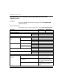
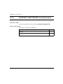
Implementing safety modules
Wiring precautions
General
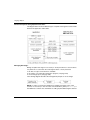
The safety system must be wired in accordance with EN60204-1. This section gives
a description of the rules for wiring and mechanically protecting cables.
The entire safety system, the ES PBs or PSs, TSX PAY 2•2 modules, protection
fuses and auxiliary relays are incorporated in housings with an IP54 minimum
protection index as per EN954-1.
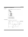
Grounding
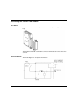
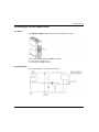
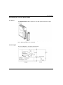
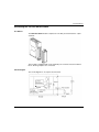
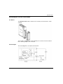
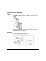
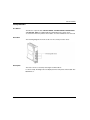
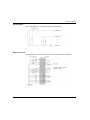
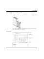
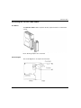
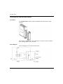
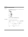
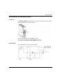
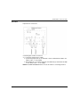
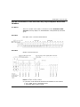
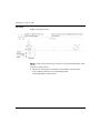
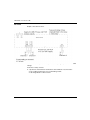
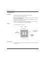
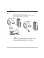
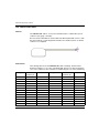
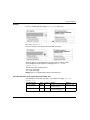
The module has no grounding terminal on its front panel. Depending on the
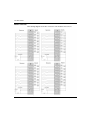
TSX CPP •02 cable being used, the 0 VDC can be grounded (cf. EN60204-1)
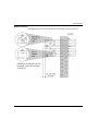
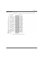
directly via the TELEFAST ABE-CPA13.
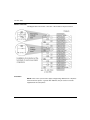
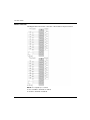
NOTE: the TSX CPP 301 cable has no ground connection.
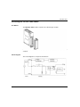
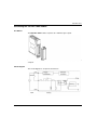
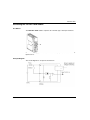
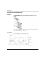
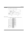
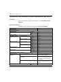
Protection of safety system
Errors within the safety modules can be propagated to the outside of the module,
particularly to the external supply in use: short circuits within the module can cause
a supply voltage avalanche or a supply malfunction if it is not protected. For this, a
1 A (gL) quick-blow fuse is placed in the control section of the relays, given that
maximum consumption is 200 mA.
NOTE: this fuse, called F1, is an active element of the safety system.
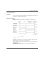
The module also contains a current limiting device set to 750 mA in order to detect
inter-channel short circuits on the ES PBs or PSs. The external supply is protected
in the event of this happening, and an error is indicated on the safety system.
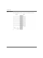
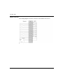
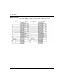
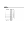
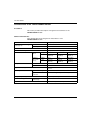
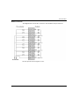
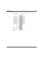
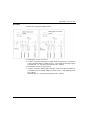
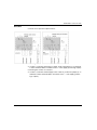
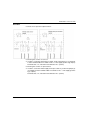
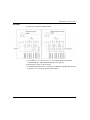
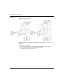
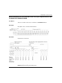
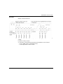
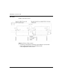
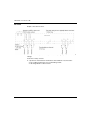
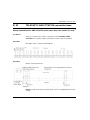
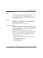
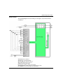
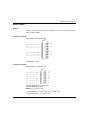
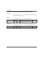
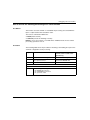
In order to guarantee the safety function, it is compulsory to use the following:
35010512 07/2011
z
on input:
z double contact ES PBs or PSs,
z the NF contacts of the guided-contact auxiliary relays in the feedback loop.
z
on output:
z two or four guided-contact auxiliary relays,
z a 4 A gL output protection fuse F2.
z
on the external module supply:
z a 1 A (gL) protection fuse F1.
361