1
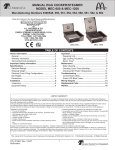
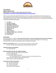
COMPONENTS (continued)
Splices (continued)
Track Splice
TRACK
500
600
700
500 DUAL
TRACK
WEIGHT LB.
5
8 1/2
17
7 1/2
DIM A
(Fig. 1)
3 3/16” 3 15/16” 4 9/16”
DIM B
DIM C
7”
8”
2 15/16” 3 11/16”
PART NO.
1503-
1603-
6 3/16”
10”
7’
5 1/4”
2 15/16”
1703-
9-2420
If your system has more than one section length of fall arrest track, each additional section is
installed in the same manner as the first, with the addition of a splice joint assembly.
Plain track: Splice joints should be within 12” of a support bracket or hanger as shown in Fig. 1.
Each section of track must have at least 2 hangers.
Splice joints should be within 18”, 48” max, of a support bracket or hanger.
The track splice joint is made from a sleeve with a total of eight set
screws threaded into the top and both sides. Slide the sleeve over
the end of the first runway track, then butt the second runway track
against the first. Center the sleeve over the joint. The two center top
set screws should be tightened slightly to push the tracks against
the base of the sleeve so that the two bottom surfaces of the track
are even. Adjust the side set screws so that the track slots are
aligned and there is a smooth transition from one track to the other,
see Fig. 2. Tighten all top set screws then side set screws for correct
track alignment.
(Fig. 2)
9
TRACK SERIES
TORQUE SPECIFICATIONS
500
600
50 IN-LBS
60 IN-LBS
EXCEEDING THESE TORQUE SPECIFICATIONS
MAY CAUSE END TRUCKS TO BIND IN TRACK