1
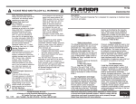
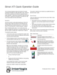
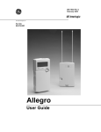
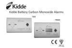
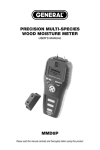
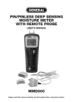
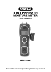
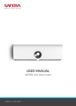
TX-6310-01-1 Carbon Monoxide Alarm Manual
Figure 1: Alarm features
WARNING: After seven years from initial power up, this alarm
will beep two times every 30 seconds to indicate that it is time
to replace the alarm. Replace the alarm immediately! It will not
detect CO in this condition.
Red Alarm LED
Green Power LED
To help identify the date to replace the alarm, an area has
been reserved on the side of the alarm. Write the “replace by”
date (seven years from power up) with a permanent marker in
the area provided.
Test/Hush button
Alarm sounder
Alarm location
CO alarms should be mounted in or near bedrooms and living
areas. We recommend that you install an alarm on each level
of your home.
Attention: Please take a few minutes to thoroughly read this
guide which should be saved for future reference and passed
on to any subsequent owner.
When choosing your installation locations, make sure you can
hear the alarm from all sleeping areas. If you install only one
CO alarm in your home, install it near bedrooms, not in the
basement or furnace room.
The TX-6310-01-1 CO alarm is only compatible with Simon XT
panels with firmware v1.4 or higher. Refer to the panel
installation instructions for revision verification details. It is
currently not compatible with other control panels. Please
contact Technical Support for any questions regarding
compatibility.
Place the alarm out of reach of children. Under no
circumstances should children be allowed to handle the CO
alarm.
Figure 2: Recommended locations
Description
The TX-6310-01-1 wireless carbon monoxide (CO) alarm
monitors the levels of CO gas and gives early warning when
potentially dangerous levels exist. It does not detect fire,
smoke, or any other gas. If a dangerous concentration of CO is
detected by patented and field-proven electrochemical sensor,
an LED indicator illuminates and an internal siren is activated
in temporal 4 pattern. The CO alarm also transmits an alarm
signal to the control panel within 15 seconds of detecting
dangerous concentration of CO gas. The control panel
activates its internal siren and reports the alarm condition to
the central monitoring station (if the system is monitored). The
CO alarm also detects low battery, wall tamper, and sensor
end-of-life. These trouble codes are transmitted to the control
panel. The alarm automatically resets when CO is no longer
detected.
Dining
Bedroom
Living room
Bedroom
Bedroom
Locations to avoid
Improper location can affect the sensitive electronic
components in this alarm. To avoid causing damage to the
unit, to provide optimum performance, and to prevent
unnecessary nuisance alarms:
The TX-6310-01-1 wireless CO alarm is Listed and compliant
with the ANSI/UL 2034 standard for CO alarms. It is intended
for residential indoor dwelling unit applications and other areas
approved by the authority having jurisdiction (AHJ). It is not
intended for use in industrial applications.
© 2011 UTC Fire & Security. All rights reserved.
Kitchen
1/8
•
Do not install in kitchens, garages, or furnace rooms that
may expose the sensor to substances that could damage
or contaminate it.
•
Do not install in areas where the temperature is colder
than 40°F (4.4°C) or hotter than 100°F (37.8°C) such as
crawl spaces, attics, porches, and garages.
•
Do not install within 5 ft. of heating or cooking appliances.
(We recommend 15 ft. to prevent nuisance alarms.)
P/N 466-2393 • REV A • ISS 14FEB11
Figure 4: Sliding the alarm on the mounting plate
•
Do not install near vents, flues, chimneys, or any
forced/unforced air ventilation openings.
•
Do not install on metal surfaces.
•
Avoid mounting in areas with a large quantity of metal or
electrical wires.
•
Do not install near ceiling fans, doors, windows, or areas
directly exposed to the weather.
•
Do not install in dead air spaces, such as peaks of vaulted
ceilings or gabled roofs, where CO may not reach the
sensor in time to provide early warning.
•
Do not install near deep-cell large batteries. Large
batteries have emissions that can cause the alarm to
perform at less than optimum performance.
5.
Do not obstruct the vents located on the alarm. Do not
place the alarm where drapes, furniture, or other objects
block the flow of air to the vents.
When replacing the batteries, use one of the following
approved brands:
•
Battery installation and replacement
Note: Place the control panel into sensor test mode prior to
replacing the batteries. If the control panel is not in sensor test
mode during battery replacement, an alarm/tamper condition
may be indicated.
To install or replace the batteries in this alarm:
1.
Slide the alarm body off of the mounting plate.
2.
If replacing batteries, remove the old batteries and
properly dispose of them as recommended by the battery
manufacturer.
3.
Install the new batteries. Note the polarity illustration in the
battery compartment (see Figure 3 below).
Figure 3: Batteries
Alarm mounting guide
Alarm mounting guide
•
•
Perform a sensor/RF test with the control panel. See “RF
communication test” on page 3
Duracell MN1500 or MX1500
Energizer E91
Note: For battery replacement information, see interlogix.com.
Use of a different battery may have a detrimental effect on the
alarm operation.
Note: Constant exposures to high or low humidity may reduce
battery life.
After installing or changing the batteries, reinstall your alarm.
Test your alarm by using the Test/Hush button and check that
the green Power LED is on.
Mounting the alarm
Note: Verify RF performance prior to permanently mounting
the alarm. See “RF communication test” on page 3.
The CO alarm can be wall mounted or ceiling mounted.
To mount the alarm:
1.
_
Battery compartment
+
_
Slide the alarm body off of the mounting plate. Place the
mounting plate in the desired location, and mark the
location of the two mounting holes. Orient the mounting
plate vertically or horizontally as shown in the following
figures.
WARNING XXXXXXXXXXXXXXXXXXX
X
XXXXXXXXXXXXXXXXXXXXXXXXXX
X
XXXXXXXXXXXXXXXXXXXXXXXXXX
X
XXXXXXXXXXXXXXXXXXXXXXXXXX
Note: The alarm can also be directly mounted to a single
gang box.
Figure 5: Vertical mounting
Mounting hole
4.
Slide the alarm body back onto the mounting plate.
Warning
Note: The mounting plate will not close if all three
batteries are not installed.
Mounting latch
XXXXxx XXX x xxx
XX XXX XXXXxxx
XXXX XXX XXXxx
XXXXXXXX XX xx
XXXXxx XXX x xx
XX XXX XXXX xx
XXXX XXX XXXxx
XXXXXXXX XX xx
XXXXxx XXX xxx
XX XXX XXXXxx
XXXX XXX XXXx
XXXXXXXX XX
XXXXxx XXX xxx
XX XXX XXXX xx
XXXX XXX X X
XXXXXXXX XXxx
xxxxxxxxxxx
XXXXxxx
xxxxxxxxxxx
Alarm
procedure
label
Mounting hole
2/8
P/N 466-2393 • REV A • ISS 14FEB11
Figure 6: Horizontal mounting
Due to the loudness of the alarm, we suggest that you place
your fingers over the sounder vent while testing your alarm.
Mounting latch
Caution: Continuous exposure to the high sound level of this
alarm over an extended period of time may cause hearing loss.
Warning
XXXXxx XXX x xxx
XX XXX XXXXxxx
XXXX XXX XXXxx
XXXXXXXX XX xx
XXXXxx XXX x xx
XX XXX XXXX xx
XXXX XXX XXXxx
XXXXXXXX XX xx
XXXXxx XXX xxx
XX XXX XXXXxx
XXXX XXX XXXx
XXXXXXXX XX
XXXXxx XXX xxx
XX XXX XXXX xx
XXXX XXX X X
XXXXXXXX XXxx
xxxxxxxxxxx
XXXXxxx
xxxxxxxxxxx
Mounting
hole
Mounting
hole
The CO alarm provides three test modes:
•
•
Alarm procedure label
2.
3.
•
Normal CO alarm test. Conducts an internal self test and
tests the sounder.
RF communication test. Tests the communication path
with the control panel.
CO alarm functional gas test. Tests the functional
operation of the CO sensing element.
Insert the two screws provided and secure the mounting
plate to the wall or ceiling surface. (If mounting in
plasterboard or drywall, drill a 3/16 in. hole and use the
plastic anchors provided.)
Normal CO alarm test
1.
After the mounting plate is secured, slide the alarm over
the mounting plate (see Figure 4 on page 2).
Wait at least 10 minutes after installation to test the CO
alarm.
2.
Make sure the green Power LED is flashing for normal
operation.
Important labels provided
3.
Set the control panel to sensor test mode.
Two labels have been provided that have important information
on what to do in case of an alarm. Add the phone number of
your emergency service provider in the space provided. Place
one label next to the alarm after it is mounted, and one label
near a fresh air source such as a door or window.
4.
Press and hold the Test/Hush button until the unit beeps
once (approximately 1 second), and then release the
button. If the unit is operating properly, you will hear four
quick beeps, followed by 5 seconds of silence, followed by
four quick beeps.
5.
At the control panel, exit sensor test mode.
Programming
The following section provides a general guideline for
programming (learning) the unit into control panel memory.
Refer to the panel documentation for complete programming
details.
To add the CO alarm to panel memory:
1.
Set the panel to program mode.
2.
Proceed to the Learn/Add Sensors menu.
3.
Select the desired sensor number.
4.
Trip the wall tamper by removing the alarm body from the
mounting plate.
5.
When the panel prompts you for sensor group number,
enter the appropriate group number based on the system
panel.
Note: This test mode does not test communication with the
control panel. You will receive a “Sensor Test Fail or Abort”
message when the control panel exits sensor test mode.
RF communication test
This section provides general guidelines for testing the CO
alarm with the panel. Refer to the specific panel documentation
for complete testing details.
Before testing, ensure that your control panel is set to sensor
test mode. Setting your panel to sensor test mode prevents an
alarm signal from being transmitted to the central monitoring
station (if you have a monitored system).
1.
Wait at least 10 minutes after installation to test the CO
alarm.
2.
Make sure the green Power LED is flashing for normal
operation.
3.
Set the control panel to sensor test mode.
4.
Press and hold the Test/Hush button until the unit beeps
two times (approximately 5 seconds), and then release the
button. If the unit is operating properly, you will hear four
quick beeps. The unit will send the RF test packets after
the first four beeps.
5.
The control panel will beep and display the number of RF
packets received.
Note: This unit is sealed. The cover is not removable.
6.
At the panel, exit sensor test mode.
WARNING: The control panel must be placed into sensor test
mode while conducting any tests. Placing the control panel into
sensor test mode for all testing helps to protect against false
alarms and unintentional central station reporting.
CO inspection and functional gas test
(for qualified service technicians only)
6.
At the panel, exit program mode.
7.
Place the alarm body back onto the mounting plate.
Note: Each CO alarm is programmed with a unique ID when
manufactured. The unique ID is enrolled into the control panel
at the time of installation, allowing the CO alarm to
communicate with that specific control panel.
Testing
P/N 466-2393 • REV A • ISS 14FEB11
Note: Consult the most recent version of NFPA 720 for more
information regarding the requirement for functional testing of CO
alarms and/or your Local Authority Having Jurisdiction (AHJ).
3/8
A canned CO testing agent must be used for the CO functional
gas test.
1.
Wait at least 10 minutes after installation to test the CO
alarm.
2.
Make sure the green Power LED is flashing for normal
operation.
3.
Set the control panel to sensor test mode.
4.
Press and hold the Test/Hush button until the unit beeps
three times (approximately 10 seconds), and then release
the button. The unit will enter the functional gas test mode.
The Power LED will blink once per second while in
functional test mode.
5.
Apply UL approved CO test agent to the slit as shown in
Figure 7 below. When CO is detected, the unit will activate
a CO alarm. The unit will send RF test packets to the
control panel when the CO alarm is activated.
Figure 7: CO testing slit
Tamper condition does not restore:
•
•
•
Make sure the CO alarm body is properly installed on the
mounting plate.
Make sure there are no trouble indications at the CO
alarm.
Make sure that you are using a compatible control panel
(see “Specifications” below).
If a tamper alarm occurs:
•
•
Make sure that you are using a compatible control panel
(see “Specifications” below).
Make sure that the control panel is in sensor test mode
during sensor testing.
Alarm/open condition does not restore:
•
•
Make sure that the CO alarm condition has cleared at the
CO alarm.
Make sure that you are using a compatible control panel
(see “Specifications” below).
Specifications
CO testing slit
Compatible panels
Simon XT (firmware 1.4 or greater) from
UTC Fire & Security
Power
Three AA batteries
Battery type
1.5 VDC alkaline
Required batteries
6.
The control panel will beep and display the number of RF
packets received.
Duracell MN 1500, Duracell MX1500,
Energizer E91
Sensor
Electrochemical
7.
At the control panel, exit sensor test mode.
Sensor life
7 years
8.
Exit functional gas test mode:
Frequency
319.5 MHz
Supervisory interval
64 minutes
Audible alarm
Temporal 4
Alarm response times
70 PPM = 60-240 min.
150 PPM = 10-50 min.
400 PPM = 4-15 min.
Dimensions
4.68 x 2.75 x 1.85 in. (119 x 70 x 47 mm)
Storage temperature
-4 to 140°F (-20 to 60°C)
Operating environment
Temperature
Relative humidity
40 to 100°F (4.4 to 37.8°C)
10 to 95% noncondensing
Press and release the Test/Hush button; or
A 2 minute timeout will automatically cause the CO to
return to normal operating mode.
Troubleshooting
This information is provided to help you diagnose and solve
various problems that may arise while configuring or using the
wireless CO alarm.
Unit does not power up properly or reports low battery:
•
•
•
Make sure the batteries are fully seated within the battery
compartment and the polarity is correct.
Make sure that all three batteries are installed.
Check the battery voltage (1.5 VDC nominal per battery).
Control panel does not respond:
•
•
•
•
4/8
Use the 60-401 RF Sniffer to make sure the CO alarm is
sending messages for activation.
Move or rotate the CO alarm position.
Make sure the CO alarm is properly enrolled into the
control panel.
Make sure that you are using a compatible control panel
(see “Specifications” below).
Regulatory information
ETL rating
ANSI/UL 2034
FCC compliance
This device complies with part 15 of the FCC
Rules. Operation is subject to the following two
conditions: (1) This device may not cause harmful
interference, and (2) this device must accept any
interference received, including interference that
may cause undesired operation.
FCC ID: B4Z-929A-CO
P/N 466-2393 • REV A • ISS 14FEB11
Operation characteristics
Table 1: Operation characteristics
LED Display
Alarm sound
Unit status
Control panel status
Recommendation
Green Power
LED flashes
every 30
seconds.
None.
Normal DC
operation (sensing
no CO) and with
good batteries.
Normal operating
condition.
None.
Carbon monoxide Red Alarm LED Four quick beeps,
5 seconds
flashes with
alarm
silence,
beeps.
repeating.
Alarm condition.
Dangerous
concentrations of
CO detected.
Alarm condition.
See “Alarm procedure” on page 8.
Low battery /
low battery hush
Red Alarm LED One quick beep
flashes every
every 60
60 seconds.
seconds.
Batteries need to be
replaced.
Trouble condition,
trouble beeps every 60
seconds.
Replace all three AA batteries.
Alarm end-of-life
indicator
Red Alarm LED Two quick beeps
every 30
flashes two
times every 30 seconds.
seconds.
End of CO alarm
life.
Trouble condition,
trouble beeps every 60
seconds.
Press the Test/Hush button and
release. This will silence the end-of-life
signal for up to three days. After three
days, the unit will resume end-of-life
chirps. Hush mode will silence the
alarm ten times or up to 30 days. After
30 days, the unit can no longer be
hushed. Replace the CO alarm
immediately. The unit will not respond
to CO.
Trouble/service
alarm
Red Alarm LED One quick beep
every 30
flashes every
seconds.
30 seconds.
Unit is in trouble
condition.
Trouble condition,
trouble beeps every 60
seconds.
Replace batteries. If condition
continues, unit has malfunctioned.
Replace immediately. Unit will not
respond to CO.
Error condition
Red Alarm LED Constant alarm.
constantly on.
Very low battery or
unit malfunction.
Trouble condition,
trouble beeps every 60
seconds.
Replace batteries. If condition
continues, unit has malfunctioned.
Replace immediately. Unit will not
respond to CO.
Test mode
Red Alarm LED Four quick beeps,
flashes with
5 seconds
silence, repeated
beeps.
once.
Normal operation
when Test/Hush
button is pressed.
Sensor test mode
CO not detected. Alarm for test
purposes only.
Tamper
Red Alarm LED One quick beep
every 30
flashes every
seconds.
30 seconds.
Unit is in tamper
condition.
Trouble condition,
trouble beeps every 60
seconds.
Place alarm body back onto mounting
plate. If condition continues, unit has
malfunctioned. Replace immediately.
Normal operation
Maintenance tips
•
To keep your alarm in good working order:
•
•
•
•
•
•
Perform a CO alarm test once a week (see “Normal CO
alarm test” on page 3).
Vacuum the alarm cover once a month to remove
accumulated dust.
Never use detergents or solvents to clean the alarm.
Chemicals can permanently damage or temporarily
contaminate the sensor.
Avoid spraying air fresheners, hair spray, paint, or other
aerosols near the alarm.
Do not paint the unit. Paint will seal the vents and interfere
with proper sensor operation.
Move the CO alarm to a remote location, to prevent possible
damage or contamination of the sensor, prior to performing any
of the following:
P/N 466-2393 • REV A • ISS 14FEB11
Press Test/Hush button and release.
This will silence the low battery audible
chirp between 8 and 11 hours allowing
for a more convenient time to replace
the batteries.
Staining or stripping floors or furniture, painting or wallpapering.
Using aerosols or adhesives.
WARNING: Reinstall the CO alarm as soon as possible to
assure continuous protection.
The following is a list of substances that at high levels can
damage the CO sensor or cause temporary readings that are
not CO readings:
Ethylene, ethanol, alcohol, iso-propanol, benzene, toluene,
ethyl acetate, hydrogen, hydrogen sulfide, and sulfur dioxide.
Also most aerosol sprays, alcohol-based products, paint,
thinner, solvent, adhesive, hair spray, after shave, perfume,
auto exhaust (cold start), and some cleaning agents.
5/8
Information about carbon monoxide
What CO alarms can and cannot do
Carbon monoxide is a colorless, odorless, and tasteless poison
gas that can be fatal when inhaled. CO inhibits the blood’s
capacity to carry oxygen.
CO alarms provide early warning of the presence of CO,
usually before a healthy adult would experience symptoms.
This early warning is possible however, only if your CO alarm
is located, installed, and maintained as described in this
manual.
Periodically review this alarm manual and discuss your CO
alarm emergency procedure with all members of your family.
Never ignore a CO alarm. A true alarm is an indication of
potentially dangerous levels of CO. CO alarms are designed to
alert you to the presence of CO before an emergency - before
most people would experience symptoms of CO poisoning,
giving you time to resolve the problem calmly.
Determine if anyone in the household is experiencing
symptoms of CO poisoning. Many cases of reported CO
poisoning indicate that while victims are aware they are not
well, they become so disoriented they are unable to save
themselves either by exiting the building or calling for
assistance. Also, young children and household pets may be
the first affected. You should take extra precautions to protect
high-risk persons from CO exposure because they may
experience ill effects from CO at levels that would not ordinarily
affect a healthy adult.
Symptoms of CO poisoning
The following common symptoms are related to CO poisoning
and should be discussed with ALL members of the household:
•
Mild exposure = Slight headache, nausea, vomiting,
fatigue (often described as “flu-like” symptoms).
•
Medium exposure = Severe throbbing headache,
drowsiness, confusion, fast heart rate.
•
Extreme exposure = Unconsciousness, convulsions,
cardio-respiratory failure, death.
If you experience even mild symptoms of CO poisoning,
consult your doctor immediately.
Conditions that can produce carbon monoxide
•
Excessive spillage or reverse venting of fuel burning
appliances caused by:
•
Outdoor ambient conditions such as wind direction
and/or velocity, including high gusts of wind; heavy air
in the vent pipes (cold/humid air with extended
periods between cycles).
•
Negative pressure differential resulting from the use
of exhaust fans.
•
Simultaneous operation of several fuel burning
appliances competing for limited internal air.
•
Vent pipe connection vibrating loose from clothes
dryers, furnaces, or water heaters.
•
Obstructions in or unconventional vent pipe designs
which amplify the above situations.
•
Extended operation of unvented fuel burning devices
(range, oven, fireplace, etc.).
•
Temperature inversions which can trap exhaust gasses
near the ground.
•
Car idling in an open or closed attached garage, or near a
home.
6/8
Because carbon monoxide is a cumulative poison, long-term
exposures to low levels may cause symptoms, as well as
short-term exposures to high levels. This unit has a timeweighted alarm, the higher the level of CO present, the sooner
the alarm will be triggered.
This CO alarm can only warn you of the presence of CO. It
does not prevent CO from occurring, nor can it solve an
existing CO problem. If your unit has alarmed and you’ve
provided ventilation by leaving your windows and doors open,
the CO buildup may have dissipated by the time help
responds. Although your problem may appear to be
temporarily solved, it is crucial that the source of the CO is
determined and that the appropriate repairs are made.
CO alarm have limitation. Like any other electronic device, CO
alarms are not fool-proof. CO alarms have a limited operational
life. You must test your CO alarm weekly, because it could fail
to operate at any time.
If your CO alarm fails to test properly, or if its self-diagnostic
test reveals a malfunction, immediately have the unit replaced.
This alarm will not monitor CO levels while in an trouble
condition.
CO alarm can only sense CO that reaches the unit’s sensor. It
is possible that CO may be present in other areas without
reaching the alarm. The rate and ability with which CO reaches
the alarm may be affected by:
•
Doors or other obstructions.
•
Fresh air from a vent, an open window, or other source.
•
CO being present on one level of the home and not
reaching a CO alarm installed on a different level. (For
example, CO in the basement may not reach an alarm on
the second level, near the bedrooms).
For these reasons, we recommend you provide complete
coverage by placing a CO alarm on every level of the home.
CO alarms should not be used to detect the presence of
natural gas (methane), propane, butane, or other combustible
fuels.
Instruct children never to touch or otherwise interfere with the
alarm. Warn children of the dangers of CO poisoning.
P/N 466-2393 • REV A • ISS 14FEB11
Important warning statements
Contact information
This carbon monoxide alarm is designed to detect carbon
monoxide from ANY source of combustion. It is NOT designed
to detect smoke, fire, or any other gas.
For servicing or contact information, see interlogix.com.
WARNING: Carbon monoxide alarms are not smoke alarms.
This carbon monoxide alarm is not a substitute for installing
and maintaining an appropriate number of smoke alarms in
your home.
This CO alarm will not sense smoke, fire, or any poisonous gas
other than carbon monoxide even though carbon monoxide
can be generated by fire. For this reason you must install
smoke alarms to provide early warning of fire and to protect
you and your family from fire and its related hazards.
Caution: This alarm will only indicate the presence of carbon
monoxide at the sensor. Carbon monoxide may be present in
other areas.
WARNING: This product is intended for use in ordinary indoor
locations of family living units. It is not designed to measure
compliance with Occupational Safety and Health
Administration (OSHA), commercial, or industrial standards. It
is not suitable for installation in hazardous locations as defined
in the National Electric Code.
The installation of this device should not be used as a
substitute for proper installation, use and maintenance of fuel
burning appliances, including appropriate ventilation and
exhaust systems. It does not prevent CO from occurring, nor
can it solve an existing CO problem.
For residential consumers, please contact your local security
system installation company for product replacement service.
Product returns from security professionals and installers
Before you can return any product to UTC Fire & Security, you
must obtain a return material authorization (RMA). This applies
to all product returns, including warranty repair/replacements,
non-warranty repairs, advance replacements, and credit
returns.
Security Customer Services:
Phone: 888-437-3287
FAX: 503-691-7566
Email: [email protected]
You will need to have the product and following information
ready:
•
•
•
Original PO number (not required for distribution partners)
SKU/part number
Serial number
Manufacturing information
Manufactured by Interlogix, a UTC Fire and Security company,
1275 Red Fox Road, Arden Hills, MN 55112.
WARNING: This device is designed to protect individuals from
acute effects of carbon monoxide exposure. It may not fully
safeguard individuals with specific medical conditions.
If in doubt, consult a medical practitioner. Individuals with
medical problems may consider using warning devices which
provide audible and visual signals for carbon monoxide
concentrations under 30 PPM.
This carbon monoxide alarm requires a continuous supply of
electrical power - it will not work without power.
This alarm has not been investigated for carbon monoxide
detection below 70 PPM.
P/N 466-2393 • REV A • ISS 14FEB11
7/8
Alarm procedure
2533-7201-00
8/8
P/N 466-2393 • REV A • ISS 14FEB11