1
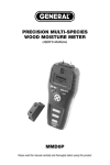
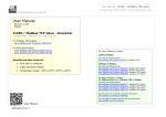
PIN/PINLESS DEEP SENSING
MOISTURE METER
WITH REMOTE PROBE
USER’S MANUAL
MMD900
Please read this manual carefully and thoroughly before using this product.
TABLE OF CONTENTS
Introduction . . . . . . . . . . . . . . . . . . . . . . . . . . . . . . . . 3 – 5
Key Features . . . . . . . . . . . . . . . . . . . . . . . . . . . . . . . . . . 5
What’s in the Case . . . . . . . . . . . . . . . . . . . . . . . . . . . . . 6
Product Overview . . . . . . . . . . . . . . . . . . . . . . . . . . . 6 – 7
Setup Instructions . . . . . . . . . . . . . . . . . . . . . . . . . . . . . 7
Install Battery . . . . . . . . . . . . . . . . . . . . . . . . . . . . . . . . 7
Operating Instructions . . . . . . . . . . . . . . . . . . . . . . 8 – 12
Measuring Moisture Levels . . . . . . . . . . . . . . . . 8 – 10
Advanced Setup Instructions . . . . . . . . . . . . . . 10 – 12
Checking Calibration . . . . . . . . . . . . . . . . . . . . . . . . 12
Specifications . . . . . . . . . . . . . . . . . . . . . . . . . . . . . . . . 13
Maintenance Tips . . . . . . . . . . . . . . . . . . . . . . . . . . . . . 13
Warranty Information . . . . . . . . . . . . . . . . . . . . . . . . . . 14
Return for Repair Policy . . . . . . . . . . . . . . . . . . . . . . . 15
2
Thank you for purchasing General Tools & Instruments’ MMD900 Pin/Pinless
Deep Sensing Moisture Meter with Remote Probe. Please read this user’s
manual carefully and thoroughly before using the meter.
The MMD900 is designed for use in woodworking, water damage restoration,
building construction and home renovation. Examples include:
• Checking for moisture on or below the surface of carpets and
sub-flooring
• Measuring the surface moisture content of wood, drywall or concrete
before painting, wallpapering, sealing or treating
• Locating water leaks above ceilings, below floors or behind walls
• Selecting dry lumber
The meter senses the moisture level of a material using either of two
techniques:
1. Inferring the material’s electrical conductivity from the current flow
induced between a pair of steel pins placed on or into the material. The
wetter a material, the higher its conductivity. The MMD900 is equipped
with two pairs of test pins—one pair on the top of the instrument and the
other at the end of a cable and remote probe that can fit in tighter spaces.
2. Measuring the change in the material’s capacitance produced by the
slight spreading of a local electric field generated by the meter. When
the meter is powered on, two plates inside the back of the MMD900’s
housing are charged with opposite polarity and pulsed at a high
frequency. This causes current to flow, creating a three-dimensional
electromagnetic wave at radio frequency that extends about 2 in.
(50mm) perpendicular to the meter. When the back of the meter is
placed against a wet material, the increased capacitance of the material
distorts the wave’s electric field to an extent that can be measured. The
distortion—called the fringing field effect—is proportional to the
material’s moisture level.
WHICH SENSOR SHOULD YOU USE?
It depends on the application. The pinless (capacitive) sensor is the only choice
for estimating the surface or internal moisture level of materials like finished
wood, paint or wallpaper that cannot be marred by pinholes. If accurate
readings are important, the pin sensor is the only option because the pinless
sensor can only provide relative readings.
3
The distinction between absolute and relative readings is important to
understand. The moisture level measurements made by either pair of test
pins—on the instrument or on the remote probe—are displayed in units of
%WME (Wood Moisture Equivalent) simultaneously on a 0-99.9 count digital
LCD and a 40-LED analog bar graph. Pin measurements are accurate within
3% of the reading plus 5 digits.
By contrast, readings made by the pinless sensor are simultaneously displayed
with no units on the LCD and on a second scale (called REL) of the bar graph.
Although the pinless readings have no accuracy specification, they are
nonetheless useful for quickly comparing the moisture levels of materials, or
the wetness of different areas of the same material. Two possible uses for the
relative readings are:
1. Determining whether two pieces of wood to be joined have roughly the
same moisture content (which means they will dry out at the same rate
without warping).
2. Locating the source of a water leak above a ceiling, by comparing the
REL readings at various points on it. If the ceiling is level, the point with
the highest REL reading is below the source of the leak.
The biggest advantage of the pinless sensor is its ability to sense moisture up
to 2 in. below or behind the surface of a material. The stainless steel test pins
of the MMD900 can also sense moisture just below the surface of some
materials. However, for hard materials like wood or concrete, measurements
made by the meter’s test pins mostly represent surface moisture content
because: 1) Moisture close to the surface has a greater effect on a reading than
moisture deep below it; and 2) The pins of the MMD900 are too short to be
driven deep into a hard material. The pins at the top of the meter are 15mm
(0.6 in.) long and the pins on the remote probe are 10mm (0.4 in.) long.
For softer materials like soil, paper or powders, pin measurements are more
likely to reflect the average moisture level of the material between its surface
and the penetration depth of the pins (usually far less than 0.6 or 0.4 in.).
Other features of the MMD900 include the following:
• Any reading (%WME or REL) can be held by pushing a front-panel button.
Doing so—called locking or “freezing” the reading—makes it possible to make
a measurement in a dark place, hold it, and display it later in a better-lighted
area.
4
• The 40-LED analog bar graph groups LEDs of three different colors (green,
yellow and red) into low, medium and high moisture bands. Each readout
(%WME or REL) can be accompanied by a beeper that can be programmed to
sound in different ways in response to different moisture levels or operations.
The correlations make it easy to use sight and/or sound to pinpoint areas of
peak or relative wetness. The beeper can be disabled without affecting
measurements.
• An auto power off function that can be triggered by three, five or 10 minutes
of inactivity.
• The protective cover for the meter’s test pins can be used to manually check
the meter’s calibration. Alternatively, the meter can automatically check its
calibration each time it is powered on.
• A display icon indicates when the meter’s 9V battery is low on charge.
KEY FEATURES
• Two measurement modes: Pin (conductivity-based) and pinless
(based on the fringing field effect)
• Two sets of test pins: on top of the meter and at the end of 46 in. remote
cable
• Pin measurement accuracy of ±3%
• Pinless mode measurement depth of 2 in. below surface
• Displays %WME and relative readings simultaneously on two displays:
0 to 99.9 count jumbo LCD with 0.9 in. (23mm) digits, and 40-dot tri-color
LED bar graph
• Manual or automatic calibration checking
• Data hold (display lock or “freeze”) function
• User-programmable beeper function, backlight function and auto power off
time
• Low battery warning
• Includes two pairs of replacement test pins
• Spare pins storage compartment
5
WHAT’S IN THE CASE
The MMD900 comes in a custom molded plastic case along with a remote
pin-type probe and cable, a 9V battery, two pairs of replacement pins and this
user’s manual.
PRODUCT OVERVIEW
The figure shows all of the controls, indicators and physical features on the
front, bottom, top, back and right side of the MMD900. Familiarize yourself with
their positions and functions before moving on to the Setup Instructions.
B
D
E
A
C
P
F
O
G
H
I
% WM E
90
70
60
50
40
30
J
REL
CAL
% WM E
85
75
REL
65
B .L .
55
40 SET
30
20
21
18
18
16
15
14
12
9
10
6
8
6
K
N
3
0 Se n s e
Pin 0
C
A
L
S
E
T
HOLD
M
L
6
A. Calibration check holes
B. Protective cover
C. 15mm replaceable test pins
D.
Indicates display is locked (frozen)
E. Measurement mode indicator (REL shown)
F.
Indicates beeper is enabled
G.
Indicates battery is weak
H. Sensing area (on back of meter)
I. Jumbo LCD display
J. Five-function Mode button
K. Four-function
button
L. Slots for holding protective cover (on bottom of meter)
M. Battery/spare pins compartment cover (on back of meter)
N. Tri-color 40-LED analog bar graph
O. Remote probe with 10mm test pins (shown with protective cap on)
P. Jack for remote probe
SETUP INSTRUCTIONS
INSTALL BATTERY
To open the battery compartment, turn the meter over and lift the tab on the
bottom of the battery compartment cover. Remove the cover and set it aside.
Then plug the included 9V battery into the wired socket inside the
compartment. The terminals of the battery and the socket mate in only one
way, with the smaller male terminal plugging into the larger female terminal.
Close the battery compartment by replacing its cover and snapping it shut.
7
OPERATING INSTRUCTIONS
To power on the meter, press the
button and hold it for at least three
seconds. (To power off the meter, follow the same instruction.)
You can use the meter immediately to measure moisture levels using the
factory-set defaults for beeper and backlight operation and auto power off
activation time. By default:
• The beeper is enabled, and beeps faster the higher the readout above
17%WME in pin measurement mode (17 in REL mode).
• The auto power off function is disabled.
• The backlight is off.
To change the default settings for the beeper, backlight or auto power
function, follow the Advanced Setup Instructions beginning on p. 10. At a
minimum, General recommends changing the default for the auto power off
function to “enabled”. If you leave the auto power off function disabled, you run
the risk of discharging the meter’s battery if you forget to power the meter off
when you are finished using it.
MEASURING MOISTURE LEVELS
Surface moisture levels should be measured by the test pins if the surface
being tested can tolerate pinholes. If it cannot, use the meter’s pinless sensor.
Internal moisture levels can be gauged by the pinless sensor for comparison
purposes.
The first step in measuring the surface moisture level of a material is to decide
whether to use the test pins on top of the meter or the test pins at the end of
the remote probe. Choose the remote probe if:
• Access to the target surface is limited (for example, if the surface is in
close quarters or a corner; the remote probe is slightly narrower than
the meter).
• You need to make one or more measurements above shoulder height,
near floor level, around a corner, or at any angle that makes it hard or
impossible to read the display. In situations like these, it’s easier to use
the meter by cradling it in your off hand, with the display facing you,
while using your dominant hand to position the remote probe.
8
To use the remote probe, remove the small rubber yellow plug from the jack
on the right side of the meter (callout P of the figure). Then insert the white plug
at the end of the cable into the jack.
To make a surface moisture level measurement, press the Mode button as
many times as necessary until the text “%WME” appears on the top line of the
LCD. Then press the test pins of the meter or the probe against the target
material. The material’s surface moisture level will be displayed as a
percentage on both the LCD and the LED bar graph.
The bar graph uses LEDs of three different colors (green, yellow and red) to
indicate different moisture level ranges (low, medium and high, respectively).
Readings below 17% are considered low, readings between 17% and 30%
medium, and readings above 30% high. If the beeper is enabled with the
factory-default setting, it will beep faster the higher the moisture level rises
above 17%.
To gauge the internal or surface moisture level of a material, enter REL
mode by pressing the Mode button as many times as necessary until the text
REL appears on the top line of the LCD. To establish a baseline for relative
readings, press the area of the back cover marked “Pinless Sensor” against a
material known to be completely dry. The meter should read “0” on both the
LCD and LED bar graphs. Then press the back of the meter against one or more
points on the target surface and compare the readings.
Some measurement tips:
1. For best results, press the pinless sensor against a flat area of the target
material.
2. When holding the sensor against a material, keep your hand and fingers
as far away from the sensing area as possible.
3. The dimensions of the target surface should be at least as large as those
of the sensing area: 1.6 x 1.6 in. (40 x 40mm).
4. Never use force to drive the test pins into a hard surface.
5. Measurements of wood are skewed by two variables: ambient humidity
and the density of the wood species. The best way to compensate for
the effect of these variables is to develop your own moisture level
curves, based on your experience working with different species of
wood on a day-to-day basis.
9
To scan a material for an area of peak wetness in either measurement
mode (%WME or REL), first make sure that the beeper is enabled (indicated by
the
icon on the top line of the LCD). If the icon is present, scan the
material while paying attention to the beeper’s frequency. The faster the beeper
beeps, the wetter an area is. Near the high end of the meter’s measurement
range, the beeping sounds almost constant.
If the beeper has been disabled, to re-enable it you must power off the meter
and then change the beeper’s default setting using the Advanced Setup
instructions in the next section.
To hold a measurement, press the
button briefly. The display will “freeze”
with the held value, along with a
(lock) icon at upper right. To unlock the
display, press the
button briefly again.
ADVANCED SETUP INSTRUCTIONS
In Setup mode, you can change the default settings for the meter’s beeper and
backlight and auto power off and calibration check functions.
To enter Setup mode, power off the meter by pressing the
button and
holding it for at least three seconds. Then power the meter back on in a special
way by simultaneously pressing the
and Mode buttons and holding them for
at least three seconds. Doing this will cause the beeper to sound, the backlight
to come on and the word “SEtUP” to scroll across the LCD.
After a few seconds, the LCD will read out “0 = 0”. In this format, the left digit
represents the Option No. and the right digit stands for the current setting for
that option. For example, “0 = 0” is shorthand for Option 0, Setting 0.
10
The table below details the five function options available to you in Setup mode.
Function
Option No.
Setting
Action
(Left Digit) (Right Digit)
Default
Settings
Source
0
0
1
Loads factory default settings
Loads user’s default settings
Backlight comes on for 30 seconds
Beeper
1
0
3
Programs beeper to beep faster the higher the
moisture level above 17%WME (17 in REL mode)
Programs beeper to beep faster the higher the
moisture level
Programs beeper to sound when switching
between measurement modes
Disables beeper. Removes
icon from display
1
2
Auto power
off
2
0
1
2
3
Disables auto power off function
Sets auto power off interval to 3 minutes
Sets auto power off interval to 5 minutes
Sets auto power off interval to 10 minutes
Backlight
3
0
1
Disables display backlight
Enables display backlight
Calibration
Check
4
0
1
Enables manual calibration checking by user
Programs meter automatically check calibration
following power on
The factory default setting for all five functions—including the source of the
default settings—is 0.
To change any or all settings to your choice(s), you must first change the setting
of Option 0 from 0 to 1. Opportunities to change the settings of the other four
functions from their factory defaults are then made available in order, from
Option 0 to Option 4. As each Option is presented, you can change its setting or
leave the existing setting unchanged. In either case, you must confirm (save)
the setting to allow the sequence to continue.
It’s important to understand that in Setup mode you have 30 seconds to
confirm the setting of each Option. If you take longer than 30 seconds to
confirm any setting, the MMD900 will automatically exit Setup mode and enter
Measurement mode.
11
To change any setting, use the Mode button to cycle through the choices
(0 or 1 for Options 0, 3 and 4; 0, 1, 2 or 3 for Options 1 and 2). When the setting
you want appears as the right digit on the display, press the button to save
it. Each time you save a setting, the display advances to the next Option. To
leave a setting unchanged, press the button to advance to the next Option.
Once a setting has been chosen for Option 4, the meter will automatically exit
Setup mode and enter Measurement mode. You cannot access the Options out
of sequence. For example, if you have disabled the beeper (by pressing the
button with “1 = 3” on the display), you cannot re-enable the beeper without
powering off the meter and re-entering Setup mode.
The one exception to this rule is the setting of the display backlight. You can
turn the backlight on or off by pressing the Mode button and holding it for at
least three seconds.
CHECKING CALIBRATION
Option 4 gives you two choices for checking the calibration of the meter.
Choosing Setting 0 lets you check the calibration manually. Setting 1
automatically checks the calibration of the meter each time it is powered on.
To check the meter’s calibration manually, press the and Mode buttons
at the same time while operating in %WME measurement mode. This will
cause the text “CAL” to flash twice on the display and the beeper to sound
twice. Remove the protective cap from the top of the meter, taking care not to
stab yourself with the two sharp test pins beneath it. Then flip the cap over and
place the two holes in its top over the meter’s two test pins. The display should
read 40% ±3%.
If the calibration check produces a reading higher than 43% or lower than
37%, and the meter is still under warranty, call General's Customer Service
Department at 212-431-6100 to arrange to return the meter for service or
replacement.
12
SPECIFICATIONS
Measurement Ranges
Measurement Accuracy
Length of Test Pins
Length of Remote Cable
Measurement Depth (pinless mode)
Pinless Sensing Area
LCD Range/Size
LCD Resolution
Bar Graph Composition
Bar Graph Resolution
Auto Power Off
Low Battery Warning Level
Current Consumption
Calibration Point
Operating Temperature
Dimensions
Weight
Power Source
0 to 99.9% WME and 0 to 99 REL
±3% of reading + 5 digits in pin mode
15mm (0.6 in.) on top of meter; 10mm (0.4 in.) on
remote probe; 10mm and 15mm (spares)
46 in. (1.168m)
2 in. (51mm)
1.6 x 1.6 in. (40 x 40mm)
99.9 count with 0.9 in. (23mm) high digits
0.1%
40 LEDs of 3 colors: green (0 to17%), yellow
(17 to 30%) and red (>30%)
±1 LED (±2.5%)
After 3, 5 or 10 minutes (user selectable) with
0% reading
<6.5VDC
<70mADC
39.4%
32° to 122°F (0° to 50°C) @<80% relative humidity
9 x 2.75 x 1.625 in. (229 x 70 x 41mm)
8 oz. (249g)
9V battery (included)
MAINTENANCE TIPS
When the
icon appears at the upper left of the LCD, it’s time to replace
the 9V battery that powers the meter (although measurements will remain valid
for several hours after the icon first appears). To replace the battery, follow the
Setup Instructions on p. 7.
When the tips of the meter’s factory-installed 15mm test pins, or the tips of the
10mm factory-installed test pins on the remote probe show signs of wear,
replace them with a pair of 10mm or 15mm pins included in the case.
Remove the battery when storing the meter for an extended period of time.
Never drop or disassemble the meter or immerse it in water.
13
WARRANTY INFORMATION
General Tools & Instruments’ (General’s) MMD900 Pin/Pinless Deep Sensing
Moisture Meter with Remote Probe is warranted to the original purchaser to be
free from defects in material and workmanship for a period of one year. Subject
to certain restrictions, General will repair or replace this instrument if, after
examination, the company determines it to be defective in material or
workmanship.
This warranty does not apply to damages that General determines to be from
an attempted repair by non-authorized personnel or misuse, alterations, normal
wear and tear, or accidental damage. The defective unit must be returned to
General Tools & Instruments or to a General-authorized service center, freight
prepaid and insured.
Acceptance of the exclusive repair and replacement remedies described herein
is a condition of the contract for purchase of this product. In no event shall
General be liable for any incidental, special, consequential or punitive damages,
or for any cost, attorneys’ fees, expenses, or losses alleged to be a
consequence of any damage due to failure of, or defect in any product
including, but not limited to, any claims for loss of profits.
14
RETURN FOR REPAIR POLICY
Every effort has been made to provide you with a reliable product of superior
quality. However, in the event your instrument requires repair, please contact
our Customer Service to obtain an RGA (Return Goods Authorization) number
before forwarding the unit via prepaid freight to the attention of our Service
Center at this address:
General Tools & Instruments
80 White Street
New York, NY 10013
212-431-6100
Remember to include a copy of your proof of purchase, your return address,
and your phone number and/or e-mail address.
15
GENERAL TOOLS & INSTRUMENTS
80 White Street
New York, NY 10013-3567
PHONE (212) 431-6100
FAX (212) 431-6499
TOLL FREE (800) 697-8665
e-mail: [email protected]
www.generaltools.com
MMD900 User’s Manual
Specifications subject to change without notice
©2011 GENERAL TOOLS & INSTRUMENTS
NOTICE - WE ARE NOT RESPONSIBLE FOR TYPOGRAPHICAL ERRORS.
MAN#MMD900 7/26/2011