1
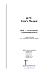
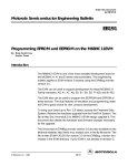
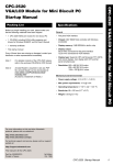
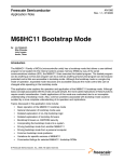
P11-DOS User’s Manual
68HC11 Microcontroller
Programming Software
Products Described
P11.EXE – 68HC11 Bootloader Program for DOS
68HC11 Devices Supported
MC68HC711E20
MC68HC711E9
MC68HC811E2
MC68HC711D3
MC68HC11A1/A8
MC68HC711K4
T
The Engineers Collaborative, Inc.
Web Site at http://www.tec-i.com
Email [email protected]
P11-DOS USER'S MANUAL
* * * IMPORTANT WARRANTY AND LIABILITY INFORMATION * * *
The Engineers Collaborative, Inc. makes no warranties, expressed or implied for this software. No
warranty of fitness for a particular purpose is offered. The user is advised to test the software thoroughly
before relying on it. The user assumes the entire risk of using the product. The total liability of The
Engineers Collaborative, Inc. is limited to the purchase price of the product, and does not cover any lost
profits, special, incidental or consequential damages, or any claim against the purchaser by any party.
* * * SOFTWARE LICENSE STATEMENT * * *
US copyright law and international treaty provisions protect this software. Therefore, you must treat this
software just like a book, with the following exception. The Engineers Collaborative, Inc. authorizes you
to make archival copies of the software for the sole purpose of backing-up our software and protecting
your investment from loss. By saying, just like a book, The Engineers Collaborative, Inc. means that the
software cannot be used by two different people in two different places at the same time.
* * * OTHER * * *
The information contained in this manual has been carefully checked and is believed to be accurate and
complete at the time of printing. However, no responsibility is assumed for errors that might appear. The
Engineers Collaborative, Inc. reserves the right to make changes to the product and/or the manual at any
time without notice. Furthermore, The Engineers Collaborative, Inc. assumes no liability arising out of
the use or application of any of its products. No part of this document may be copied or reproduced in any
form or by any means without prior written consent of The Engineers Collaborative, Inc.
(C) Copyright 1989-2004 The Engineers Collaborative, Inc.
Web Site at www.tec-i.com
Email [email protected]
All Rights Reserved
Printed in the U.S.A.
The Engineers Collaborative Inc.
Page 2
P11-DOS USER'S MANUAL
TABLE OF CONTENTS
1.0 INTRODUCTION ......................................................................................................................................... 4
2.0 SYSTEM REQUIREMENTS........................................................................................................................ 4
3.0 DEVICES SUPPORTED............................................................................................................................... 4
4.0 GETTING STARTED................................................................................................................................... 4
4.1 Software Installation......................................................................................................................... 4
5.0 68HC11 SPECIAL BOOTSTRAP MODE.................................................................................................... 6
6.0 THE P11.EXE PROGRAM........................................................................................................................... 7
6.1 Invoking P11.EXE............................................................................................................................ 7
6.1.1 Command Line Options ................................................................................................... 7
6.1.2 Command Line Only Options .......................................................................................... 8
6.2 P11 Screen Display........................................................................................................................... 9
6.3 P11.EXE Menu Options................................................................................................................... 9
Change Device Type.................................................................................................................. 9
Change Buffer Fill Character ................................................................................................. 10
Change config Register ........................................................................................................... 10
Load Object Code File to Buffer............................................................................................. 10
Device Menu............................................................................................................................ 11
Initialize Device .......................................................................................................... 11
Communications Test.................................................................................................. 11
Blank Check Device.................................................................................................... 11
Bulk Erase EEPROM .................................................................................................. 12
Read Device Contents into Buffer................................................................................ 12
Verify Device Contents against Buffer......................................................................... 12
Program &Verify Config Register ............................................................................... 12
Program &Verify EEPROM ........................................................................................ 12
Program &Verify EPROM .......................................................................................... 12
Program & Verify Entire Device.................................................................................. 12
Exit to Main Menu ...................................................................................................... 12
Examine/Edit Buffer Contents................................................................................................ 12
Save Buffer in a File................................................................................................................ 13
Change communications Port................................................................................................. 13
Help......................................................................................................................................... 13
Exit to DOS ............................................................................................................................. 13
7.0 P11 TUTORIAL EXAMPLE SESSION ..................................................................................................... 13
The Engineers Collaborative Inc.
Page 3
P11-DOS USER'S MANUAL
1.0 INTRODUCTION
This manual provides information on our P11.EXE program, software used for programming
68HC11 family microcontrollers.
The program takes input from object code files created with 68HC11 assemblers or compilers
and provide a means of programming or burning this data into the memory of 68HC11 family
microcontrollers. The object code files may be in Motorola S-record, Intel Hex or binary
memory image formats. The software also allows the operator to perform many other useful
programming functions such as erasing, blank checking & verifying devices, displaying, editing,
exporting and changing the format of the object code files and filling unused memory locations
with a user specified "fill" byte. The software was designed to work with our P11 Programming
Board but will also work with any hardware that supports the 68HC11 special bootstrap mode of
operation.
TECI provides several other development tools for 68HC11 family microcontrollers such as our
Cross Assemblers WASM11.EXE and TASM11.EXE, real time in-circuit emulator TECICEHC11, WP11 a version of this program for Windows, and our P11 programmer board.
2.0 SYSTEM REQUIREMENTS
P11.EXE requires a minimally configured PC capable of running DOS and one free serial port
designated as COM1-COM2. P11.EXE will not run under Windows 2000 or Windows XP but
will run under the other versions of Windows.
3.0 DEVICES SUPPORTED
Presently, these programs support the following 68HC11 family members:
MC68HC711E9
MC68HC711E20
MC68HC811E2
MC68HC711D3
MC68HC11A1/A8
MC68HC711K4
4.0 GETTING STARTED
4.1 Software Installation
The software is contained in a single .ZIP file called P11DOS.ZIP. This is a standard ZIP file
that can be unzipped with PKUNZIP, WINZIP, ZIPMAGIC and many others. You may have
downloaded the P11DOS.ZIP file from our web site at www.tec-i.com or received the file on a
single 3.5" floppy diskette. To install P11-DOS just unzip the files into the directory of choice on
your PC.
The files extracted from P11DOS.ZIP are:
The Engineers Collaborative Inc.
Page 4
P11-DOS USER'S MANUAL
P11.EXE
This is the DOS version of the program.
P11.HLP
This is the help file for P11.EXE.
P11-DOSManual.PDF
This manual in Adobe Acrobat .PDF format. The Adobe Acrobat reader
software is available free of charge from a number of online sites such as:
www.adobe.com/products/acrobat/readstep.html
P11_A8.MIK
This is an HC11 object code file in Motorola S-Record format that
contains the programming code for MC68HC711A1/A8 devices.
WP11.EXE downloads this code to the programmer when A1 or A8
devices are being programmed.
P11_D3.MIK
This is an HC11 object code file in Motorola S-Record format that
contains the programming code for MC68HC711D3 devices. WP11.EXE
downloads this code to the programmer when D3 devices are being
programmed.
P11_E2.MIK
This is an HC11 object code file in Motorola S-Record format that
contains the programming code for MC68HC811E2 devices. WP11.EXE
downloads this code to the programmer when E2 devices are being
programmed.
P11_E9.MIK
This is an HC11 object code file in Motorola S-Record format that
contains the programming code for MC68HC711E9 devices. WP11.EXE
downloads this code to the programmer when E9 devices are being
programmed.
P11_E20.MIK
This is an HC11 object code file in Motorola S-Record format that
contains the programming code for MC68HC711E20 devices. WP11.EXE
downloads this code to the programmer when E20 devices are being
programmed.
P11_K4.MIK
This is an HC11 object code file in Motorola S-Record format that
contains the programming code for MC68HC711K4 devices. WP11.EXE
downloads this code to the programmer when K4 devices are being
programmed.
E2_TEST.S19
This is an object code file in Motorola S-Record format. It is used for test
programming of MC68HC811E2 devices.
K4EEPROM.S19
This is an object code file in Motorola S-Record format. It is used for test
programming of the EEPROM memory area of MC68HC711K4 devices.
The Engineers Collaborative Inc.
Page 5
P11-DOS USER'S MANUAL
EEPROM.S19
This is an object code file in Motorola S-Record format. It is used for test
programming of the EEPROM memory area of MC68HC711A1/A8,
MC68HC711E9, and MC68HC711E20 devices. Memory locations from
$B600 through $B7FF are programmed by this file.
5.0 68HC11 SPECIAL BOOTSTRAP MODE
P11.EXE use the 68HC11 special bootstrap mode to program devices. You will need to build or
buy the circuitry required to use the special bootstrap mode. Our P11 programmer circuit board
is an example of a commercial product that has this capability. The figure below shows the
basics of this circuitry.
Special Bootstrap Circuit
Much more information on the special bootstrap mode can be found online by doing a Google
search for "68HC11 special bootstrap mode".
The Engineers Collaborative Inc.
Page 6
P11-DOS USER'S MANUAL
6.0 THE P11.EXE PROGRAM
All interactions with the programming hardware are accomplished by selecting the various
options provided by the P11.EXE program.
6.1 Invoking P11.EXE
P11.EXE is invoked by typing at the DOS prompt:
>P11<Enter>
Assuming the use of a hard disk and the use of the PATH command in the AUTOEXEC.BAT you
may invoke P11.EXE from any directory.
If there are multiple projects or multiple versions of the same project that require different
settings, then you should create a different directory for each project or version. If your project or
version requires the use of a different microcontroller, you should start P11.EXE from within
the directory of that project or version because, when P11.EXE is exited, a file called
P11.INI is created to save the current settings and this file is saved in the current directory.
Whenever you invoke the program from that directory again, the P11.INI file determines the
settings the program starts with. Any time P11.EXE is invoked from a directory that does not
contain a P11.INI file, the default settings for P11.EXE (shown below in Section 6.2) will be
in place.
Assuming the use of P11.EXE from a bootable working floppy disk with one project per disk,
you may invoke P11.EXE from the A:\ or B:\ prompt, whichever contains the floppy disk..
6.1.1 Command Line Options
Command line options take precedence over settings in the P11.INI file.
From the Command Line the user may change the Communications Port that P11.EXE starts up
with to either COM1 or COM2. The default is COM1. The communication port setting is saved
in the P11.INI file found in the directory that P11.EXE was last started up in.
For example:
C:\HC11PROJ\>p11 com1<Enter>
will start P11.EXE on COM Port 1. The COM port may also be set from the P11.EXE main
menu.
The Engineers Collaborative Inc.
Page 7
P11-DOS USER'S MANUAL
6.1.2 Command Line Only Options
There are two program options of P11.EXE that can only be modified from the Command Line.
These parameters are the Video Mode and the Program Beep.
For most circumstances the P11.EXE video is auto-sensing. However for some configurations,
notably for computers with older color video cards that have pseudo color monitors attached, the
video mode may be unacceptable.
BW80
;sets the video mode to Black & White, 80 columns
Example:
C:\HC11PROJ\>p11 BW80<Enter>
will start P11.EXE in Black & White video mode. Video modes are not saved to the P11.INI
file.
There is an optional Program Beep for those who wish it. It sounds whenever a task is
completed. This option is saved in the P11.INI file.
It may be set by typing:
C:\HC11PROJ\>p11 beep<Enter>
when beginning a P11.EXE session. To return to silent operation, type:
C:\HC11PROJ\>p11 nobeep<Enter>
at the command line when beginning the next P11.EXE session.
Command line options may be in any order:
Example:
C:\HC11PROJ\>p11 nobeep BW80<Enter>
will turn the beep off and set the video to Black & White 80 columns.
The Engineers Collaborative Inc.
Page 8
P11-DOS USER'S MANUAL
6.2 P11.EXE Screen Display
When P11.EXE is invoked, the program menu screen is displayed. It looks something like this:
This is the default setting for the P11.EXE. Before describing each of the menu options some
words on the general operation of the program are in order.
P11.EXE maintains an exact image of the microcontroller's memory in the PC. This memory
image is called the buffer. During programming operations, data from the buffer is copied
(programmed) into the memory of the microcontroller device. The buffer must be loaded with
the desired data before a programming operation is performed. The buffer can be loaded from an
object code file or from another microcontroller that already contains the desired data. The buffer
can be displayed and edited before a programming operation is performed. With this general
understanding, each of P11.EXE's options will now be described.
6.3 P11.EXE Menu Options
Change Device Type
Selecting the Change Device Type option brings up the device type selection menu that looks
like this:
With the up and down arrow keys, select the processor desired and press <Enter>.
The Engineers Collaborative Inc.
Page 9
P11-DOS USER'S MANUAL
* * * WARNING * * *
Changing the device type or even selecting the same device type as the current selection purges
the contents of the buffer. The buffer is filled with the erased state of the selected device.
Change Buffer Fill Character
When you change the 68HC11 device type the buffer fill character automatically changes to the
erased state of the selected device. You may, however, wish to change the buffer fill character to
some other value. Pressing <Enter> at this Main Menu selection will enable you to specify a
HEX value between 0H & 0FFH inclusive. Changing the buffer fill character will completely
overwrite the buffer.
Change Config Register
When you change the 68HC11 device type the Config Register value (in the PC) automatically
changes to the erased state of the selected device. You may, however, wish to change the Config
Register to some other value. Pressing <Enter> at this Main Menu selection will enable you to
specify a HEX value between 0H & 0FFH inclusive. You must be careful to specify values for
the Config Register that are valid for the selected device. Changing the Config Register in the
Main Menu will not effect the microcontroller until the Config Register is programmed from the
Device Menu.
Load Object Code File to Buffer
This command is used to load an object code file into the host PC's RAM buffer.
When this option is selected, the operator is prompted to enter the file name of the object code
file. The complete file name must be entered including the file extension. File formats are
automatically detected by P11.EXE, and may be either Motorola S-Record, Intel Hex or a
binary memory image. Binary files must be 64K bytes in length. If the file name is entered
correctly and can be opened and read by P11.EXE, a memory image of the target chip is created
in the buffer. If the file can not be opened, an error message is displayed and the operator is
given another chance to enter the file name. This continues until the operator enters a correct file
name or presses <Esc>. The operator is then given the option of exiting the screen.
You may then Examine/Edit Buffer Contents. For a complete description of this option see
below.
* * * WARNING * * *
The order in which you use the commands from the main menu is very important. You should
select the desired HC11 device before you fill the buffer with programming data. When you
change the device type (or even select the same device type from the Change 68HC11 Device
Type menu) the buffer is filled with the erased state of the selected device. Next if you wish to
put a different fill character in the buffer you must do so before you Load Object Code File to
Buffer. If you load the object code file first, then change the fill character, the fill character will
completely overwrite the contents of the buffer erasing any information currently in it. After
selecting the device type and changing the fill character, the object code file may be loaded.
The Engineers Collaborative Inc.
Page 10
P11-DOS USER'S MANUAL
Device Menu
These sub menus let you select various options for each respective selected device.
For each command option there is a text screen displayed on the host computer. The user must
follow these instructions and wait for the completion of the command.
Initialize Device
P11 uses the HC11 special bootstrap mode during programming. This mode requires that
special programming code be downloaded to the target device's RAM to control the
programming process. The Initialize Device menu option performs this task. No chip may be
programmed or communicated with successfully without first performing this menu function.
Normally, this initialization process has to be performed only once after the target device is
brought out of reset. It does not have to be repeated unless power is turned off to the target
device.
Communications Test
This command is used to determine if the target device is properly initialized.
Blank Check Device
Tests the target device's Config Register, EPROM and EEPROM memory to determine if
every location is in the erased state.
The Engineers Collaborative Inc.
Page 11
P11-DOS USER'S MANUAL
Bulk Erase EEPROM & Config Reg.
This menu command returns the EEPROM and Config Register in the target device to its
erased state.
Read Device Contents into Buffer
This command reads the contents of the target device's programmable memory into the RAM
buffer in the host computer.
Verify Device Contents against Buffer
This command compares the contents of the target device's programmable memory with the
contents of the P11 buffer.
Program & Verify Config Register
This command programs the value of the Config Register shown on the P11 status line into
the Config Register of the target device then tests to determine if the operation was
successful.
Program & Verify EEPROM
This command programs the contents of the EEPROM portion of the P11 buffer into the
EEPROM memory of the target device then tests to determine if the operation was
successful.
Program & Verify EPROM
This command programs the contents of the EPROM portion of the P11 buffer into the
EPROM memory of the target device then tests to determine if the operation was successful.
Program & Verify Entire Device
This command programs the contents of the EEPROM & EPROM portion of the P11 buffer
and the value of the Config Register shown on the P11 Status Line into the target device
then tests to determine if the operation was successful.
Exit to Main Menu
This option returns the user to the P11.EXE Main Menu.
This is the end of the description of the Device Menu sub menu. We will now return to a
description of the remaining selections in the Main Menu.
Examine/Edit Buffer Contents
Selecting this option allows the user to examine and/or edit the contents of the P11 buffer.
If the user wishes, the buffer may be edited by typing over the current contents of memory
locations. The cursor may be moved around the screen using the arrow keys. Pressing the TAB
key toggles the cursor between the HEX portion of the screen and the ASCII portion of the
screen. Non-HEX keys are disabled in the Hex portion of the screen, non-printable characters are
disabled in the ASCII portion of the screen.
The Engineers Collaborative Inc.
Page 12
P11-DOS USER'S MANUAL
To move through the memory map in the buffer, use the Page Up and Page Down keys. Each
page displays 256 bytes of information. The buffer varies in size according to the currently
selected device.
Save Buffer in a File
This option allows you to save the current contents of the P11 buffer in one of three object code
file formats, Motorola S-Record, Intel HEX or binary image format.
When you select this option, you are asked to name the new file. If you wish to save the file in a
directory other than the current directory you must type the full path and file name.
Change Communications Port
This option toggles the active communications port between COM 1 and COM 2. The currently
active port is displayed on the left side of the P11 status line.
Help
This option opens the help screen. The help screen may be scrolled through using the Page Up
and Page Down keys or using the arrow keys. To exit the Help screen, press <Esc>.
The help screen information is contained in a standard DOS text file. The user may edit this file
to add any additional information that may be required.
Exit to DOS
This menu selection will end the P11.EXE session. Pressing <End> will take you to this menu
selection from anywhere else in the Main Menu.
7.0 P11 TUTORIAL EXAMPLE SESSION
It is assumed that you have read the rest of this manual, installed the software in accordance with
the Getting Started section and performed the Initial Test of the P11 Programmer in accordance
with that section of this manual. It is further assumed that you are in P11.EXE at the Main Menu
level.
It is also assumed that you have a MC68HC711E9 or a MC68HC811E2 chip that can be used
with this tutorial. If you are using an E9 chip, we are not going to program the EPROM section,
we will only program the EEPROM section so the chip can be erased and re-used for another
purpose.
The steps required to program a chip are as follows:
1) Select the desired device type from the Change Device Type option of the P11 Main Menu.
2) Configure the P11 Programming Board for the selected device. This means setting the
jumpers correctly and inserting the target device into the proper socket.
* * * NOTE * * *
You must insert and remove devices from the ZIF sockets with power removed from the
programming board. This means unplugging the wall transformer.....or.....better yet, plugging the
transformer into a power strip that has a switch for turning the power on and off.
The Engineers Collaborative Inc.
Page 13
P11-DOS USER'S MANUAL
3) Load the Buffer with the data that you want to program into the target device. This is done
with the Load Object Code File into Buffer option from the P11 Main Menu. Sometimes you
may want to manually enter data into the buffer, this can be done with the Examine/Edit Buffer
Contents option from the P11 Main Menu.
4) Initialize the target device for programming by using the Initialize Device option from the
Device Menu. This places a control program in the target device's ram memory that allows
P11.EXE to control the programming process.
5) Program the target device using one of the available options in the Device Menu.
Tutorial:
1. Load the Buffer with the desired data to be programmed into the target device by selecting
the Load Object Code File to Buffer option from the P11 Main Menu.
2. Enter an object code file name, "TEST_E9.MIK" if your using an E9 or "TEST_E2.MIK" if
your using an E2 target device. Press "Y" at the "Do you want to exit this from [Y/N]?" prompt.
3. Choose the Examine/Edit Buffer Contents P11 Main Menu option, and view the object code
by using the Page Up and Page Down keys. (To edit the data, see the section Examine/Edit
Buffer Contents) Exit the screen by pressing <Esc>.
4. Select the Device Menu. Press <Enter>.
5. Select the Initialize Device menu item. Press <Enter>. You will be confronted with a
screen that shows the initialization progress. When that is complete you are free to select any of
the remaining commands in the Device Menu except for the Program & Verify EPROM and
Program and Verify Entire Device options. These two menu commands will program the
EPROM of the 68HC711E9 with the buffer contents and prevent the EPROM from being
programmed again.
6. Select the Program & Verify EEPROM if using an E9 device or Program & Verify Device if
using an E2 device. Press <Enter>. This programs the contents of the Buffer into the target
device.
7. To prove that we can read the contents of a programmed device, go back to the Main Menu
and select Change Device Type. Select the device that you are working with. This clears the
Buffer to the erased state of the selected device. Then go back to the Device Menu and select
Read Device Contents into Buffer. Then go back to the Main Menu and select Edit/Examine
Buffer Contents. You should see the data that was originally programmed into the device.
That's it! You have just performed all of the necessary steps to program an HC11 device.
We sincerely hope that after using this tool, you will consider it to be a sound investment. We
look forward to your comments and suggestions and to providing any assistance with their use
that you may require.
The Engineers Collaborative Inc.
Page 14