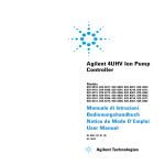
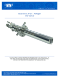
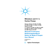
1
VacIon Plus 300 pumps User Manual 4 Installation Procedure General Information 40 Preparation for Installation 41 Installation 43 Use 45 Operating Procedure 46 Maintenance 48 Disposal 48 Original Instructions 39/90 4 Installation Procedure General Information General Information This equipment is destined for use by professionals. The user should read this instruction manual and any other additional information supplied by Agilent before operating the equipment. Agilent will not be held responsible for any events occurring due to non-compliance, even partial, with these instructions, improper use by untrained persons, non-authorized interference with the equipment or any action contrary to that provided for by specific national standards. The VacIon Plus series pumps are ion pumps commonly used to create ultra-high vacuum, due to their cleanliness, ability to pump different gases, and maintenance- and vibration-free operation. The following paragraphs contain all the information necessary to guarantee the safety of the operator when using the equipment. Detailed information is supplied in the appendix "Technical Information". This manual uses the following standard protocol: WARNING! The warning messages are for attracting the attention of the operator to a particular procedure or practice which, if not followed correctly, could lead to serious injury. CAUTION! The caution messages are displayed before procedures which, if not followed, could cause damage to the equipment. NOTE 40/90 The notes contain important information taken from the text. VacIon Plus 300 pumps User Manual / 87-900-103-01 (F) 4 Installation Procedure Preparation for Installation Preparation for Installation The pump is supplied in a special protective packing. If this shows signs of damage which may have occurred during transport, contact your local sales office. When unpacking the pump, be sure not to drop it and avoid any kind of sudden impact or shock vibration to it. Do not dispose of the packing materials in an unauthorized manner. The material is 100 % recyclable and complies with EEC Directive 85/399. CAUTION! NOTE In order to prevent outgassing problems, do not use bare hands to handle components which will be exposed to vacuum. Always use gloves or other appropriate protection. Normal exposure to the environment cannot damage the pump. Nevertheless, it is advisable to keep it closed until it is installed in the system, thus preventing any form of pollution by dust. VacIon Plus 300 pumps User Manual / 87-900-103-01 (F) 41/90 4 Installation Procedure Preparation for Installation Figure 1 42/90 VacIon Plus 300 pumps User Manual / 87-900-103-01 (F) 4 Installation Procedure Installation Installation WARNING! The pump is heavy and must be handled by means of suitable moving and handling tools. Do not install or use the pump in an environment exposed to atmospheric agents (rain, snow, ice), dust, aggressive gases, or in explosive environments or those with a high fire risk. During operation, to obtain the specified operation, the ambient temperature must be between 0 °C and +85 °C. CAUTION! The pump should be kept sealed with its pinch-off tubulation until it is ready for attachment to the vacuum system. VacIon Plus 300 pumps User Manual / 87-900-103-01 (F) 43/90 4 Installation Procedure Installation WARNING! NO! To avoid injury, never connect the high voltage to the pump before it is installed into the system and all the inlet flanges are properly connected or blanked off. The pump operation is optimized using one of the special Agilent controllers (Dual, MidiVac or MiniVac) only. CAUTION! 44/90 The safety specifications agreement using the pump is guaranteed using the Agilent controller only. VacIon Plus 300 pumps User Manual / 87-900-103-01 (F) Installation Procedure Use 4 The VacIon Plus pump can be installed in any position. For convenience, a pump is usually mounted vertically with the inlet up. For mounting other than vertical, the pump should be supported using the mounting feet at the bottom of the pump. For detailed information about the pump installation, see the appendix “Technical Information”. Use All the instructions for the correct use of the VacIon Plus pumps are contained in the control unit manual. Read the manual carefully before using the pump. Rough pumping down to 1x10⁻⁴ Torr (mbar) is recommended for the most rapid starting. Roughing with an oilsealed mechanical pump is not desirable, but when used, a trap in the roughing line is recommended to reduce pressure due to water vapor and oils from the mechanical pump. Be careful to minimize the time that this pump is open to the system and ion pump, since mechanical pump vapors will start diffusing into the system at pressures below 1x10⁻¹ Torr (mbar) and cause contamination. In systems where oils must be completely eliminated, turbopump roughing pumps should be used. Hygroscopic deposits and hydrogen absorption into titanium may cause starting times to increase with age. During exposure to air, the deposits of titanium compound absorb water vapor. In subsequent start ups, pump heating causes release of the water vapor and some previously pumped hydrogen; thus, the starting time may be lengthened. VacIon Plus 300 pumps User Manual / 87-900-103-01 (F) 45/90 4 Installation Procedure Operating Procedure Operating Procedure Check that the controller HV polarity is correct for the pump: positive polarity for Diode pumps and negative for StarCell or Triode pumps. Refer to the relevant pump control unit instruction manual and follow the procedure below when operating the pump: 46/90 1 With a clean roughing pump, establish a minimum starting pressure in the vacuum system per the table on page 9 for the type of ion pump. 2 Plug the control unit into a suitable power source and switch the power ON. 3 Observe the voltage, current, and roughing pressure. If started at 5x10⁻² Torr (mbar), a controller voltage of approximately 300 to 400 volts is typical. A current value near the short-circuit current of the control unit could indicate that an unconfined flow discharge exists in the pump and system. A temporary rise in roughing pressure will usually be noticed during any starting procedure. 4 Allow the roughing valve to remain open after turning on the ion pump until an adequate starting pressure is reached. If the ion pump voltage drops after closing the roughing valves, reopen the valve for additional rough pumping. As the pressure decreases, the voltage again will rise, and the roughing valve may be closed. 5 When the voltage has increased to 2-3 kV, place the control unit in the PROTECT condition. The system is now automatically protected against pressure increases to 10-4 Torr (mbar) when the pump is left unattended. If such an increase should occur, the control unit will be turned off automatically. 6 The pressure in the pump can also be determined by reading the current and converting this reading to pressure with the appropriate pressure versus current graph shown in the appendix “Technical Information” of this manual. VacIon Plus 300 pumps User Manual / 87-900-103-01 (F) 4 Installation Procedure Operating Procedure NOTE The steps on the pressure – current charts are a characteristic of the Dual step voltage operation. When the current drawn by the VacIon pump reaches the specified values, the controller will change the high voltage output to a lower applied voltage. 7 When venting the pump, use dry nitrogen. This will avoid water vapor absorption on the pump walls. WARNING! When employing the pump for pumping toxic, flammable, or radioactive gases, please follow the required procedures for each gas disposal. Do not use the pump in presence of explosive gases. WARNING! When the heating element is installed, do not touch the pump during the heating and cooling phases. The high temperature may cause a serious damage. CAUTION! Do not put any electronic device near the pump otherwise the magnetic field around it may cause a device malfunctioning. VacIon Plus 300 pumps User Manual / 87-900-103-01 (F) 47/90 4 Installation Procedure Maintenance Maintenance The VacIon Plus series pump does not require any maintenance. Any work performed on the pump must be carried out by authorized personnel. WARNING! Before carrying out any work on the pump, disconnect it from the High Voltage supply. If a pump is to be scrapped, it must be disposed of in accordance with the specific national standards. Disposal Meaning of the "WEEE" logo found in labels. The following symbol is applied in accordance with the EC WEEE (Waste Electrical and Electronic Equipment) Directive. This symbol (valid only in countries of the European Community) indicates that the product it applies to must NOT be disposed of together with ordinary domestic or industrial waste but must be sent to a differentiated waste collection system. The end user is therefore invited to contact the supplier of the device, whether the Parent Company or a retailer, to initiate the collection and disposal process after checking the contractual terms and conditions of sale. 48/90 VacIon Plus 300 pumps User Manual / 87-900-103-01 (F) VacIon Plus 300 pumps User Manual 5 Technical Information Description of the VacIon Pump 51 Technical Specification 53 Vaclon Plus 300 Starcell 55 Vaclon Plus 300 Diode 57 Vaclon Plus 300 Noble Diode 58 Outline Drawing 60 Stray Magnetic Field 61 VacIon Plus Pump Installation 64 Inspection Procedure 64 Visual Inspection 64 Vacuum Evaluation 65 Short Circuits 66 Typical Installation 67 Inlet Flange Connection 68 Control Unit Connection 71 Safety Interlock 72 Heater Installation 72 Heater Replacement 74 Original Instructions 49/90 5 Technical Information Disposal Bakeout Operation 74 Bakeout of Vaclon Pump with the Integral Heaters 75 Operating Procedure 76 Maintenance 77 Exchange of Pumping Element 78 Exchange of the High Voltage Feedthrough 79 Leakage Current Check 80 High-potting 81 Pump Troubleshooting 82 Vaclon Plus Pump Replacement Parts and Accessories 83 Vaclon Plus Pump Controllers 84 50/90 VacIon Plus 300 pumps User Manual / 87-900-103-01 (F) 5 Technical Information Description of the VacIon Pump Description of the VacIon Pump The Agilent VacIon Plus 300 pumps are ion pumps and are available in three types: StarCell Noble Diode Diode They operate in the pressure range from 10-2 to below 10-11 mbar. Virtually all gases and vapors can be pumped successfully with the ion pump. The pumping speed will vary depending on the system pressure, the gas type, and the applied operating voltage. The latter can be optimized using Agilent controllers to achieve the lowest possible operating pressure. The VacIon Plus StarCell pump allows starting from as high as 5x10⁻² mbar, because ions are prevented from bombarding the system and pump walls at starting pressures, and have high speed for inert gases. The VacIon Plus Diode and Noble Diode pumps require a lower starting pressure (i.e. 10-4 mbar). The tantalum in the Noble Diode pump enhances the noble gas pumping capacity, although it somewhat reduces the high getterable gas pumping speed that the standard diode pump provides. The VacIon Plus StarCell is the latest variation of the Triode configuration. Its patented design makes this ion pump the only one that can handle a high amount of Noble Gases (better than Noble Diode and Triode) and Hydrogen (comparable to the Diode). A positive polarity, high voltage supply is required to operate Diode and Noble Diode pumps. A negative polarity high voltage supply is required to operate StarCell pumps since the anode is grounded and the cathode is held at negative potential. The inlet ConFlat flange is a 8” (NW 150). VacIon Plus 300 pumps User Manual / 87-900-103-01 (F) 51/90 5 Technical Information Description of the VacIon Pump Fig. 2 shows the VacIon Plus 300 pump, Fig. 3 shows the main assemblies of the pump. Figure 2 VacIon Plus 300 pump Inlet flange Element Figure 3 52/90 Cover Magnet High voltage connector Pump main assemblies VacIon Plus 300 pumps User Manual / 87-900-103-01 (F) 5 Technical Information Technical Specification Technical Specification The following table details the main technical specifications of the VacIon Plus 300 pumps. Tab. 1 Specification Model StarCell Noble Diode Diode Nominal pumping speed for Nitrogen (*) (l/s) 240 260 300 Operating life at 1 x 10⁻⁶ mbar (hours) 80,000 50,000 50,000 Max starting current 400 mA Max baking current 50 mA Protect current 100 mA Operating voltage (max) -7000 Vdc +/- 10 % +7000 Vdc +/- 10 % d1x10-2 d1x10-3 Maximum starting pressure (mbar) Ultimate pressure Below 10-11 mbar Inlet flange 8” CFF (NW 150) AISI 304 ESR Internal volume (litres) 18.6 Maximum baking temperature (°C) 350 Temperature limits (°C): Pump Magnet Flange 400 350 500 AISI 304 SST Material: Body Cathode Titanium Titanium/ Tantalum Anode AISI 304 SST Magnet Ferrite Weight, lbs (kg) Titanium 149 (69) (*) Tested according to ISO/DIS 3556-1-1992 VacIon Plus 300 pumps User Manual / 87-900-103-01 (F) 53/90 5 Technical Information Technical Specification Figures 4 to 11 show the pumping speed vs. pressure diagrams for saturated and unsaturated pumps and the pressure vs. current diagrams for the same pump. The diagrams are for pumps con-trolled by means of a Dual controller. The pumping speed of a newly regenerated (i.e. baked) sputter ion pump decreases during operation until it reaches a stabilized level known as "saturation" (nominal pumping speed). To saturate the VacIon Plus 300 pumps, it normally requires an amount of gas equal to 10 mbar-liters. Consequently, pumps can operate for extended periods of time at low pressures in the non-saturated state, if they are properly conditioned. 54/90 VacIon Plus 300 pumps User Manual / 87-900-103-01 (F) Technical Information Vaclon Plus 300 Starcell 5 Vaclon Plus 300 Starcell Figure 4 Pumping speed vs pressure for Nitrogen Figure 5 Pumping speed vs pressure for Argon VacIon Plus 300 pumps User Manual / 87-900-103-01 (F) 55/90 5 Technical Information Vaclon Plus 300 Starcell Figure 6 56/90 Pressure vs current diagram VacIon Plus 300 pumps User Manual / 87-900-103-01 (F) Technical Information Vaclon Plus 300 Diode 5 Vaclon Plus 300 Diode Figure 7 Pumping speed vs pressure for Nitrogen Figure 8 Pressure vs current diagram VacIon Plus 300 pumps User Manual / 87-900-103-01 (F) 57/90 5 Technical Information Vaclon Plus 300 Noble Diode Vaclon Plus 300 Noble Diode 58/90 Figure 9 Pumping speed vs pressure for Nitrogen Figure 10 Pumping speed vs pressure for Argon VacIon Plus 300 pumps User Manual / 87-900-103-01 (F) Technical Information Vaclon Plus 300 Noble Diode Figure 11 5 Pressure vs current diagram VacIon Plus 300 pumps User Manual / 87-900-103-01 (F) 59/90 5 Technical Information Outline Drawing Outline Drawing The following figure shows the outline drawing for the VacIon Plus pump. Figure 12 60/90 VacIon Plus pump outline drawing VacIon Plus 300 pumps User Manual / 87-900-103-01 (F) Technical Information Stray Magnetic Field 5 Stray Magnetic Field Curves of stray magnetic field strength along the centre line of the pump and in the plane of the flange as a function of distance from the pump are shown in Figs. 14, 15, 16, 17 and 18, where Bx is the magnetic field along X axis, By is along Y axis and Bz is along Z axis. Figure 13 VacIon Plus pump axis identification Figure 14 Stray magnetic field from flange along X axis (z = 0 mm) VacIon Plus 300 pumps User Manual / 87-900-103-01 (F) 61/90 5 Technical Information Stray Magnetic Field 62/90 Figure 15 Stray magnetic field from flange along Y axis (z = 0 mm) Figure 16 Stray magnetic field from flange along X axis (z = 100 mm) VacIon Plus 300 pumps User Manual / 87-900-103-01 (F) Technical Information Stray Magnetic Field Figure 17 Stray magnetic field from flange along Y axis (z = 100 mm) Figure 18 Stray magnetic field from flange along Z axis VacIon Plus 300 pumps User Manual / 87-900-103-01 (F) 5 63/90 5 Technical Information VacIon Plus Pump Installation VacIon Plus Pump Installation Inspection Procedure VacIon Plus pumps are evacuated, baked out, sealed and leakchecked at below 1x10⁻¹⁰ mbar prior shipping. The following information and procedures can be used to optimize the vacuum integrity of a VacIon Plus pump before installation. Visual Inspection Inspect the pump and magnet for physical damage which may have occurred during shipment. Inspect the pinch-off seal. If it is open, the pump is at atmospheric pressure. WARNING! The pinch-off seal is extremely sharp. Be careful. A VacIon Plus pump that has been exposed to atmosphere during shipment, or while in storage, will operate properly if it has not been damaged. The pump is not harmed by such exposure, although it is good practice to keep it under vacuum when not in use to exclude dust and the accumulation of water vapor from the environment. 64/90 VacIon Plus 300 pumps User Manual / 87-900-103-01 (F) 5 Technical Information VacIon Plus Pump Installation Vacuum Evaluation The ion pump is shipped in an evacuated condition. Before removing the shipping flange for installation on a vacuum system, it is recommended that the pump be started briefly to verify vacuum integrity and proper operation. To verify the vacuum integrity of the new pump before venting: 1 WARNING! Connect the pump to the control unit as directed in the instruction manual of the control unit. The high voltage which is present in the ion pump from the control unit can cause severe injury or death. Be sure that the high voltage cable is proper connected to the ion pump and its power unit. Make sure that the pump is well grounded. 2 With the main power switch in the OFF position, plug the control unit into a suitable power source. 3 Turn the power to ON. 4 Observe the reading for an indication of one of the following conditions: 5 a If the pump is free of leaks and is at a low pressure, the pressure indication shall within 10 minutes fall to or below the 10-8 mbar range as the volume of gas is pumped. b If the pressure inside the pump is at or near atmospheric level, an arc may strike inside the high voltage feedthrough giving a popping sound and the pump current will fluctuate. If this occurs, turn the power OFF immediately. If the vacuum integrity has been lost, the pump should be leakchecked with a mass spectrometer leak detector before installation on the system. VacIon Plus 300 pumps User Manual / 87-900-103-01 (F) 65/90 5 Technical Information VacIon Plus Pump Installation Short Circuits If there is a short circuit between the anode and cathodes in the pump (or cathode to pump body), the short-circuit current of the control unit will be drawn and low voltage will be indicated. If a short circuit exists in the control unit or high voltage cable and connector, low voltage will also be observed when the high voltage connector is disconnected from the pump (refer to the control unit manuals). An ohm meter reading on the pump feedthrough may not be effective in finding a short. Short circuits may be caused by mechanical shock to the pump. If the pump is shorted, contact Agilent. 66/90 VacIon Plus 300 pumps User Manual / 87-900-103-01 (F) Technical Information Typical Installation 5 Typical Installation A typical installation is shown in figure 19 and consists of: 1. VacIon Plus pump. 2. A Valve to seal off the pump from the rest of the system (if required). 3. The control unit. 4. A clean roughing pump (i.e. turbo or sorption). 5. A thermocouple gauge capable of indicating pressure from atmosphere to 10-3 mbar range. 6. A valve to seal off the roughing pump from the vacuum chamber. Roughing lines are usually made of stainless steel or copper tubing, or other low vapor pressure material. 7. High voltage cable. 8. Backing pump (diaphragm or scroll). Figure 19 Typical installation VacIon Plus 300 pumps User Manual / 87-900-103-01 (F) 67/90 5 Technical Information Inlet Flange Connection Inlet Flange Connection The pump should be mounted allowing a sufficient clearance for installation and removal of the high voltage connector. The pump should be kept sealed with its pinch-off tubulation until it is ready for attachment to the vacuum system. This avoids accumulation of dust and other undesirable materials. Before breaking the pinch-off seal, consult the inspection procedure (see preceding paragraph). Vent the ion pump by opening the pinch-off tubulation in a clean area free from smog, dust, pollen, etc. Venting with dry nitrogen gas is further recommended. This can be done by placing a clean polyethylene bag over the ion pump flange. Small pumps can be placed inside of the bag. Purge the bag with clean, dry nitrogen for several minutes, then reach into the bag and release the internal vacuum using pliers to open the copper tube pinch-off. CAUTION! Do not open the pinch off-seal with a saw or grinder. These methods will cause metal particles to be drawn into the pump by the inrushing air as the pump is opened. WARNING! The pinch-off seal is extremely sharp. Be careful when opening. Watch your fingers. Use appropriate procedures to maintain the clean condition of the pump and vacuum system. Unscrew the main flange bolts and lift the blank flange with the help of a bolt screwed into the available threaded hole. Remove the ConFlat flange and the copper gasket plate. Some particles of copper oxide may adhere to the outer edge of the flange gasket. Be careful not to allow them or any other foreign materials to fall into the pump. 68/90 VacIon Plus 300 pumps User Manual / 87-900-103-01 (F) 5 Technical Information Inlet Flange Connection Connect the ion pump to the vacuum chamber with a short length and large diameter tubulation in or-der to retain as much pumping speed as possible. Proceed as follows: NOTE 1 Inspect the mating flanges for cleanliness and absence of scratches on the knife edge. 2 Place a new copper gasket between pump flange and vacuum chamber flange. 3 Bolt mating flanges of the pump to the chamber with the screws provided with the ion pump. For flanges over NW 35 (2.75" o.d.) also mount washers below the nuts and screw heads. 4 Use silver-plated screws or apply high temperature lubricant to the screw threads. Lubrication simplifies sealing and disassembly. A recommended lubricant is Fel-Pro C-100. Lubrication is essential to prevent galling of the nut and screw after bakeout. 5 Attach the nuts and tighten each one to 6 – 11 Nm (4.5 - 8 ft.-lbs) of torque. After tightening a nut, always tighten the opposite nut with respect to the center of the flange. This will partially close the gap between the flange faces. 6 Repeat the sequential tightening for two more cycles. 7 Continue tightening the bolts until the flange faces meet and a pronounced increase in torque is felt. Note that it’s not possible to install the screws from the lower side, but only from the upper side of the flange. To allow complete flexibility in the installation, a stud mounting kit is available (see Fig. 20). For ordering information refer to the “VacIon Plus Pump Replacement Parts and Accessories” paragraph. VacIon Plus 300 pumps User Manual / 87-900-103-01 (F) 69/90 5 Technical Information Inlet Flange Connection Figure 20 70/90 Stud mounting kit VacIon Plus 300 pumps User Manual / 87-900-103-01 (F) 5 Technical Information Control Unit Connection Control Unit Connection WARNING! The high voltage present in the high voltage cable which connects the control unit to the ion pump, can cause severe injury or death. Before mounting the high voltage connector of the cable on the pump high voltage feedthrough, or before removing it, be sure the main power is removed from the control unit. WARNING! To avoid injury, never connect the high voltage to the pump before it is installed into the system and all the inlet flanges are properly connected or blanked off. Make sure that the pump is well connected to the grounded vacuum system. WARNING! Before removing the high voltage connector of the cable from the control unit, be sure the main power is removed from the control unit. Wait at least 10 seconds after removing the main power from the control unit, to allow capacitors to discharge completely. To disconnect the coaxial high voltage cable from the controller, slide the safety locking sleeve (very little sleeve travel is required) from the control unit and at the same time pull on the male end of the cable connector to remove it from the socket on the control unit. VacIon Plus 300 pumps User Manual / 87-900-103-01 (F) 71/90 5 Technical Information Safety Interlock Safety Interlock The VacIon Plus pump feedthrough in conjunction with the cable P/N 929-0705, -0707, 0708 and -0709, when used with the Agilent MidiVac, DUAL and 4UHV control units, allows the operation of the “High Voltage Cable Safety Interlock” feature. When the high voltage cable connector is disconnected from the VacIon Plus pump feedthrough, the high voltage is automatically switched off by the control unit. Heater Installation The heating element (Fig. 21) is composed of two plates to be fixed to the pump case. NOTE It is advisable to make a 10 – 15 minutes initial operation of the heater in a ventilated room to allow the evaporation of residual internal alloying elements. To install the element proceed as follows (Fig. 22): 72/90 1 Before removing the pole pieces, mark their position and orientation for an easier assembly later on. 2 Position the heating plate (1) inserting the threaded pins positioned on the pump jacket into the holes of the plate. Be sure that the written heating plate side is towards you; 3 Position the other heating plate (2) in the same way as the heating plate (1); 4 Reinstall the pole pieces; 5 Position the connection box (3) on the upper side of the pump in an oppose position of the HV feedthrough with respect to the flange, and fix it to the pump case. VacIon Plus 300 pumps User Manual / 87-900-103-01 (F) Technical Information Heater Installation Figure 21 Heating element Figure 22 Heating element installation VacIon Plus 300 pumps User Manual / 87-900-103-01 (F) 5 73/90 5 Technical Information Heater Replacement Heater Replacement To replace the heater element proceed as follows: 1 Disconnect the pump from the high voltage; 2 Disconnect the heater element from the main supply; 3 Disconnect the heater plates from the pump case; 4 Disconnect the heater connection box from the upper side of the pump; 5 Install the new heater elements as described in the paragraph “HEATER INSTALLATION”. Bakeout Operation When a VacIon pump does not reach the desired base pressure, and there are no leaks, it is necessary to bake the system. This is done by heating the pump and all the components in the system, and is generally required to achieve base pressure less than 10-8 mbar. 74/90 1 Heat the pump body and the system with a bakeout oven unit or heating strips to temperatures between 150 °C and 220 °C (220 °C is the maximum allowable for most bakeable high voltage cables). This temperature is high enough to degas the pump surfaces of water vapor without damaging the magnet and high voltage connector. Note that the system components must be compatible with the bakeout temperature. The heating must be approximately even on all surfaces or evaporated water will condence on the colder surfaces resulting in an incomplete bake and preventing achievement of UHV vacuum pressure. 2 Leave the pump control unit on and monitor the pressure. Agilent recommends that current during bake not exceed 50 mA; if this value is exceeded, turn the bakeout off and then on again when low pressure is restored. To control the heaters and to monitor the high pressure limit during bakeout, an automatically controlled relay may be used. 3 Bake the VacIon Plus pump for at least 24 hours. Longer bakeout periods are recommended when the pump has been used with heavy gas loads or when UHV pressure, 10-9 mbar or less is desired. VacIon Plus 300 pumps User Manual / 87-900-103-01 (F) 5 Technical Information Bakeout Operation 4 As the pump and system cool down to room temperature, a drop in pressure should be observed. Note that the ion pump can be also baked when switched off, into an external turbo pump through a bakeable isolation valve. Bakeout of Vaclon Pump with the Integral Heaters NOTE WARNING! 1 The integral heaters are to be powered with the appropriate voltage. (Please refer to the inscription on the heaters to apply correct voltage). 2 The integral heaters are designed to provide a temperature of 250 °C to 300 °C when the pump is wrapped in a 3-fold aluminium foil. A three-layer foil wrapping is advisable and sufficient to achieve full bakeout/regeneration if the standard European heaters (230 Vac) are operated at 240 Vac, thus preventing overheating. 3 Bakeout the VacIon pump for 24 hours. If the pump is used in heavy gas load applications, it is recommended to bakeout the pump for a longer period. 4 Wait until the pump cools down to room temperature and recovers its base pressure before using it in the application. Do not touch the pump during the heating and cooling phases. The high temperature may cause serious damage. VacIon Plus 300 pumps User Manual / 87-900-103-01 (F) 75/90 5 Technical Information Operating Procedure Operating Procedure 1 Using a clean roughing pump, evacuate the system to a minimum starting pressure as stated by the technical specification. 10-6 mbar or less is recommended. To reach this pressure the use of an oil free turbo-molecular roughing pump is recommended. 2 When starting an ion pump, a slight increase in vacuum pressure is normal as the internal components are heated and outgassed. If possible leave the roughing pump connected to the system while starting the ion pump. This will make the startup faster and easier. 3 Connect the control unit to a suitable power source and switch the power on. 4 Switch on high voltage to the pump and observe the current and voltage. Fastest starting is obtained using a high applied voltage, 7 kilovolts for example. The applied voltage may be reduced later to optimize pumping and achieve the lowest vacuum pressure. 5 If started at 10-4 mbar, the voltage will start at approximately 800 volts and increase to full voltage as the pump starts operating. The current will start at several milliamps and slowly decrease to microamps or nanoamps as low vacuum pressure is achieved. 6 When first starting the pump, if the voltage de-creases instead of increasing, reduce the vacuum pressure then start the ion pump again. 7 When the pump reaches its full operating volt-age, you may close the roughing valve. 8 If the pump does not start after 30 minutes of pumping, see the section PUMP TROUBLE-SHOOTING. 9 Once the pump reaches its base pressure with stable voltage and current, the ion pump may be baked at high temperature if required per the section titled BAKEOUT OPERATION. 10 To stop the ion pump, simply switch off the high voltage. The pump surfaces will continue to pump for a few minutes depending on the system pressure. 76/90 VacIon Plus 300 pumps User Manual / 87-900-103-01 (F) 5 Technical Information Maintenance 11 When venting the pump use clean, dry nitrogen. This will avoid water absorption on the pump surfaces and make subsequent pump downs easier. Maintenance WARNING! The high voltage present in the high voltage cable which connects the control unit to the ion pump, can cause severe injury or death. Before mounting the high voltage connector of the cable on the pump high voltage feedthrough, or before removing it, be sure the main power is removed from the control unit. Before removing the high voltage connector of the cable from the control unit, be sure the main power is removed from the control unit. Wait at least 10 seconds after removing the main power from the control unit, to allow capacitors to discharge completely. VacIon Plus pumps are maintenance free. In case of life time expiry or premature failure of the pump, please contact your nearest Agilent sales/service office for repair. The VacIon Plus 300 pumps are designed with exchangeable highvoltage feedthrough and pump elements. VacIon Plus 300 pumps User Manual / 87-900-103-01 (F) 77/90 5 Technical Information Maintenance Exchange of Pumping Element Remove the internal high-voltage connections. 78/90 1 Remove the internal high-voltage connections. 2 Remove the element holding brackets. 3 Pull the element out of the pocket and remove it through the inlet flange. 4 Clean the internal part of the pump with the appropriate solvent. 5 Put in the new element through the inlet flange. Make sure that the element is fixed at its rear by the two press-formed buttons of the element pocket, and at its front by the element holding clamp. 6 Reattach the high-voltage connections and test for continuity from the feedthrough. 7 Place a blank flange over the pump inlet and leak-check it with a leak detector. 8 Bake out the blanked off pump while it is operating, and leave it to cool down; then verify that the base pressure is below 10-9 mbar. VacIon Plus 300 pumps User Manual / 87-900-103-01 (F) Technical Information Exchange of the High Voltage Feedthrough 5 Exchange of the High Voltage Feedthrough CAUTION! The high voltage feedthrough contains a ceramic insulator that can be damaged if excessive force is applied in torque, in bending, or in tension. When installing or removing the feedthrough, the applied torque should not exceed 2 Nm. Rotate the feedthrough gently when making the threaded connection to avoid excessive force. 1 Remove the 6 bolts of the Mini-ConFlat flange connection (see Fig. 23). 2 Remove the cable connection disc. 3 Gently relieve the feedthrough from the metal gasket connection and turn the feedthrough counterclockwise until it is completely detached from the internal high voltage threaded connection. 4 Replace the feedthrough and the copper gasket, making sure that the feedthrough is connected to the pumps internal connector. Check that the feedthrough is not shorted. 5 Bake out the pump while it is operating, and leave it to cool down; then verify that the base pressure is below 10-9 mbar. Figure 23 High voltage feedthrough connection VacIon Plus 300 pumps User Manual / 87-900-103-01 (F) 79/90 5 Technical Information Exchange of the High Voltage Feedthrough Leakage Current Check If the pump current reading is to be used as pres-sure measurement, check the pump leakage cur-rents as follows: 80/90 1 Turn off the pump control unit. 2 Remove the pump magnet. 3 Turn on the pump control unit and wait for cur-rent stabilization. The current reading should not be higher than 300 nA. Make sure that the control unit and the high voltage cable leakage current is negligible. 4 If leakage current comes from the pump, per-form "high-potting" per the following procedure; then recheck the pump and install the magnet. 5 If it is not possible to "high-pot" the pump, the pressure reading is biased by the leakage current value. VacIon Plus 300 pumps User Manual / 87-900-103-01 (F) 5 Technical Information Exchange of the High Voltage Feedthrough High-potting A constant pump current when no vacuum leak exists is often caused by field emission currents which prevent the use of the pump current as a UHV pressure indicator. To reduce this field emission current, "high-potting" should be performed. "High-potting" is the term used to describe the application of higher than normal operating voltage (8 kV AC, max. 50 mA) for the purpose of burning off "whiskers" (sharp edges) on the pump cathode. High-potting should be done under vacuum and preferably without pump magnets installed (to reduce the drawn current). High-potting must be done carefully and in voltage steps since uncontrolled arcing inside the pump can cause permanent damage. Therefore slowly increase the applied voltage and watch the current meter for indication of arcing inside the pump as whiskers are burned away. If arcing occurs wait at this voltage until the current is stable again. Then slowly increase voltage again in steps up to a maximum voltage. The maximum voltage may be applied to the pump for a period of about 15 seconds. This should effectively remove any "whiskers" or sharp edges on the pump cathode. WARNING! Voltages developed in the High Potter power supply are potentially lethal. Use caution during operation and ensure correct grounding connection. VacIon Plus 300 pumps User Manual / 87-900-103-01 (F) 81/90 5 Technical Information Pump Troubleshooting Pump Troubleshooting Tab. 2 Symptom Possible cause Correction procedure 1) – Slow starting Starting vacuum pressure too high. Reduce pressure to 10-5 mbar recommended 10-4 mbar minimum. 2) – Slow starting (more than 30 minutes). Air leaks which limit pressure to above 10-6 mbar and cause longer starting time. Leak check the vacuum system with a helium leak detector. 3) – Slow pump-down due to long exposure of viton parts to air. Viton releases considerable gas after long exposure to air. (A bell-jar system which reached 2 x 10⁻⁸ mbar in 24 hours after 30 minutes air exposure, will only reach 1 x 10⁻⁷ mbar in 24 hours after 20 hours air exposure). With the system under vacuum, pump for several days, or heat to 100-150 °C for up to 15 hours. 4) – Slow pump-down due to absorption of vapours on pump and system walls. Vapours and gases admitted to a system are absorbed on the walls of the system and pump. Subsequent reduction in pressure depends on the rate of depletion of this vapour. Heavy hydrocarbons are most troublesome because of their relative low vapour pressure and they are very difficult to remove, even by baking. Bake the system walls, thereby accelerating the desorption process. Baking mobilizes the vapours so they can be cracked and pumped by discharge (see section “BAKEOUT OPERATION”). 5) – Slow starting or slow pumpdown. High voltage feedthrough is leaking. Replace the feedthrough. 6) – Current higher than expected at any given pressure. Ion pump leakage current causing higher pressure reading. Highpot the pump. 82/90 VacIon Plus 300 pumps User Manual / 87-900-103-01 (F) 5 Technical Information Vaclon Plus Pump Replacement Parts and Accessories Symptom Possible cause Correction procedure 7) – System fails to achieve desired UHV vacuum pressure. System not fully baked. Water vapor limits base pressure. Bake the system walls, thereby accelerating the desorption process. Baking mobilizes the vapours so they can be cracked and pumped by discharge (see section “BAKEOUT OPERATION”). 8) – System fails to achieve desired UHV vacuum pressure. System not appropriately cleaned for UHV. Excessive outgassing from walls limits base pressure. Clean all components for UHV and bake the system again. Vaclon Plus Pump Replacement Parts and Accessories Tab. 3 Part Number Basic pump Diode Noble Diode Starcell 919-1610 919-1620 919-1640 Pump with options With heaters installed (120 V) (220 V) 919-1611 919-1612 919-1621 919-1622 919-1641 919-1642 Double-ended 919-1650 919-1660 919-1680 Double-ended with heaters (120 V) installed (220 V) 919-1651 919-1652 919-1661 919-1662 919-1681 919-1682 Cables and accessories HV rad. Resist. cable, with interlock VacIon Plus 300 pumps User Manual / 87-900-103-01 (F) 929-0705 83/90 5 Technical Information Vaclon Plus Pump Controllers Replacement parts HV Feedthrough 959-5125 Pumping elements (q.ty 4 needed) 919-9040 Heaters (power: 480 W) (120V) (220V) 919-9045 919-9030 919-0075 919-0074 Copper gasket for 6” inlet flange (10-pack, individually sealed) Nut and bolt set for 6” inlet flange FG-0600-CI FB-0450-C12 Copper gasket for 1 1/3" CF feedthrough flange (10-pack, individually sealed) FG-0133-CI Nut and bolt set for 1 1/3" CF feedthrough flange, 8-32x3/4 (25pack) FB-0133-C For a complete overview of Agilent's extensive vacuum product line, please refer to the Agilent Vacuum Catalogue. Vaclon Plus Pump Controllers The following controller series are available to supply the VacIon Plus pumps: MiniVac Dual 4UHV Please refer to the Agilent Vacuum Catalogue to choose the correct controller for each pump. 84/90 VacIon Plus 300 pumps User Manual / 87-900-103-01 (F) Request for Return Form Sales and Service Offices United States Agilent Technologies Vacuum Products Division 121 Hartwell Avenue Lexington, MA 02421 - USA Tel.: +1 781 861 7200 Fax: +1 781 860 5437 Toll-Free: +1 800 882 7426 India Agilent Technologies India Pvt. Ltd. Vacuum Product Division G01. Prime corporate Park, 230/231, Sahar Road, Opp. Blue Dart Centre, Andheri (East), Mumbai – 400 099.India Tel: +91 22 30648287/8200 Fax: +91 22 30648250 Toll Free: 1800 113037 Italy Agilent Technologies Italia S.p.A. Vacuum Products Division Via F.lli Varian, 54 10040 Leini, (Torino) - Italy Tel.: +39 011 997 9111 Fax: +39 011 997 9350 Toll-Free: 00 800 234 234 00 Southeast Asia Agilent Technologies Sales Sdn Bhd Vacuum Products Division Unit 201, Level 2 uptown 2, 2 Jalan SS21/37, Damansara Uptown 47400 Petaling Jaya, Selangor, Malaysia Tel : +603 7712 6106 Fax: +603 6733 8121 Taiwan Agilent Technologies Taiwan Limited Vacuum Products Division (3F) 20 Kao-Shuang Rd., Pin-Chen City, 324 Taoyuan Hsien , Taiwan, R.O.C. Tel. +886 34959281 Toll Free: 0800 051 342 Canada Central coordination through: Agilent Technologies Vacuum Products Division 121 Hartwell Avenue Lexington, MA 02421 - USA Tel.: +1 781 861 7200 Fax: +1 781 860 5437 Toll-Free: +1 800 882 7426 Japan Agilent Technologies Japan, Ltd. Vacuum Products Division 8th Floor Sumitomo Shibaura Building 4-16-36 Shibaura Minato-ku Tokyo 108-0023 - Japan Tel.: +81 3 5232 1253 Fax: +81 3 5232 1710 Toll-Free: 0120 655 040 UK and Ireland Agilent Technologies UK, Ltd. Vacuum Products Division 6 Mead Road Oxford Industrial Park Yarnton, Oxford OX5 1QU – UK Tel.: +44 (0) 1865 291570 Fax: +44 (0) 1865 291571 Toll free: 00 800 234 234 00 China Agilent Technologies (China) Co. Ltd Vacuum Products Division No.3, Wang Jing Bei Lu, Chao Yang District, Beijing, 100102 China Tel.: +86 (10) 6439 7718 Toll-Free: 800 820 6556 France Agilent Technologies France Vacuum Products Division 7 Avenue des Tropiques Z.A. de Courtaboeuf - B.P. 12 91941 Les Ulis cedex - France Tel.: +33 (0) 1 69 86 38 84 Fax: +33 (0) 1 69 86 29 88 Toll free: 00 800 234 234 00 Germany and Austria Agilent Technologies Vacuum Products Division Alsfelder Strasse 6 Postfach 11 14 35 64289 Darmstadt – Germany Tel.: +49 (0) 6151 703 353 Fax: +49 (0) 6151 703 302 Toll free: 00 800 234 234 00 Korea Agilent Technologies Korea, Ltd. Vacuum Products Division Shinsa 2nd Bldg. 2F 966-5 Daechi-dong Kangnam-gu, Seoul Korea 135-280 Tel.: +82 2 3452 2452 Fax: +82 2 3452 2451 Toll-Free: 080 222 2452 Mexico Agilent Technologies Vacuum Products Division Concepcion Beistegui No 109 Col Del Valle C.P. 03100 – Mexico, D.F. Tel.: +52 5 523 9465 Fax: +52 5 523 9472 Other Countries Agilent Technologies Italia S.p.A. Vacuum Products Division Via F.lli Varian, 54 10040 Leini, (Torino) Italy Tel.: +39 011 997 9111 Fax: +39 011 997 9350 Toll-Free: 00 800 234 234 00 Benelux Agilent Technologies Netherlands B.V. Vacuum Products Division Herculesweg 8 4338 PL Middelburg The Netherlands Tel.: +31 118 671570 Fax: +31 118 671569 Toll-Free: 00 800 234 234 00 Singapore Agilent Technologies Singapore Pte. Ltd, Vacuum Products Division Agilent Technologies Building, 1 Yishun Avenue 7, Singapore 768923 Tel : (65) 6215 8045 Fax : (65) 6754 0574 © Agilent Technologies, Inc. 2011 Printed in ITALY 05/2011 Publication Number: 87-900-103-01 (F) Customer Support & Service NORTH AMERICA: Toll Free: 800 882 7426, Option 3 [email protected] EUROPE: Toll Free: 00 800 234 234 00 [email protected] PACIFIC RIM: please visit our website for individual office information http://www.agilent.com Worldwide Web Site, Catalog and Order On-line: www.agilent.com Representative in most countries 12/10