1
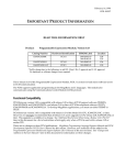
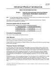
May 6, 1996
GFK-1081B
IMPORTANT PRODUCT INFORMATION
READ THIS INFORMATION FIRST
Product:
Programmable Coprocessor Module
IC697PCM711U
IC697PCM711SX
This is release 4.01 of the IC697 Programmable Coprocessor Module (PCM). It uses the new PCMA3
board. The software functionality of this release is substantially identical to release 3.03. All existing
PCM applications that have been tested with the PCMA3 and this firmware release operate as expected.
The PCM supports application programming in the MegaBasic and C languages. The module also
communicates using the Communications Control Module (CCM) protocol.
Table 1. Product Catalog Number
Catalog Number
Replaces
IC697PCM711U
and
IC697PCM711SX
IC697PCM711T
The hardware and software identification for this release is summarized in the following table.
Table 2. Hardware and Software Identification
Catalog
Number
Board
Identification
Board Revision
EPROM
Label
EPROM
Location
IC697PCM711U
PCMA3
44A735360-G01R03 and later versions
387-055A4.01
387-056A4.01
U59
U60
IC697PCM711SX
PCMA1
PCMA2
44A719374-G01R05 and later versions
44A730912-G01R03 and later versions
387-055A4.01
387-056A4.01
U59
U60
Upgrade Information
The PCMA1 and PCMA2 board revisions shown above can be upgraded to release 4.01 using the
optional field upgrade kit 44A286371-G13.
2
Important Product Information
GFK-1081B
Hardware Compatibility
Modules that were shipped as IC697PCM711A through IC697PCM711G are based on the PCMA1
hardware platform. These modules have PCMA1 screened on the component side of the printed
wiring board, at the center of the rear edge. A sticker on the top edge of the board identifies the
hardware revision level. Revisions R05 through R11 can be upgraded to release 4.01 using the field
update kit identified above. These modules must be labeled as IC697PCM711SX by attaching the
corresponding label provided in the upgrade kit.
PCMA1 hardware revisions R04 and earlier may not be upgraded to release 4.01.
PCMA1 hardware revisions R05 (shipped as IC697PCM711B) and R06 (shipped as IC697PCM711C)
may be updated release 4.01, but additional restrictions apply. See Special Operation Notes for
information on using PCMA1 revision R05 in a rack powered by the IC697 100 watt power supply,
IC697PWR711. Also see Additional Restrictions With PCMA1 Revisions R05 and R06.
All PCMA2 modules (shipped as IC697PCM711J through IC697PCM711P) may be upgraded to
release 4.01 using the field upgrade kit specified above. These modules have PCMA2 screened on
the component side of the printed wiring board, at the center of the rear edge. They must also be
labeled as IC697PCM711SX by attaching the corresponding label provided in the upgrade kit.
Functional Compatibility
PCM firmware version 4.01 is compatible with release 1.00 or later of both the IC641SWP063A and
IC641SWP023A versions of PCM Support Software (TERMF), and release 2.04 or later of both the
IC641SWP061B and IC641SWP021A versions of PCM Development Software (PCOP). To develop
MegaBasic applications, you must use either TERMF or PCOP.
PCM firmware version 4.01 is also compatible with release 2.04 or later of IC697 PLC CPUs.
Documentation
Data Sheet: GFK-0164F, or later version
Quick Reference Guide: GFK-0260E, or later version.
User Manuals: There are no changes to these PCM publications: MegaBasic Programming Language
Reference Manual, GFK-0256D; and PCM Development Software (PCOP) User’s Manual, GFK-0487C, for
this release. The Programmable Coprocessor Module and Support Software User’s Manual, GFK-0255H,
was recently revised.
Special Operational Notes
VME Memory Allocation
IC697 PCM applications that allocate blocks of VME memory and also use PCM services to transfer
data between the PCM and PLC CPU may experience data corruption when more than 4K bytes of
data are transferred in a short period of time. For example, two or more MegaBasic NOWAIT
SYSREAD or SYSWRITE requests that overlap in time can cause this problem. PLC COMMREQ
function blocks that overlap PCM service requests can also contribute. This problem can be avoided
by following the recommendations below.
AllocationMethod - PCM applications should allocate VME memory at startup time and retain it
indefinitely. The Reserve_dp_buff service should be used, and the application should specify the
Important Product Information
3
GFK-1081B
memory block address to place the block at the top of VME memory. If two or more PCM tasks use
VME memory, a single block large enough for all their needs should be allocated with one call to
Reserve_dp_buff.
Memory Block Size and Location - For IC697 PCMs using PCMA2 or PCMA3 hardware and firmware
release 4.01 or later, the size and starting offset parameters for Reserve_dp_buff should be chosen
from pairs in this table:
Table 3. Recommended Combinations of Reserve_dp_buff Parameters
For PCMs With 64K Byte VME Memory
Size in
Bytes
Starting
Offset
Size in
Bytes
Starting
Offset
Size in
Bytes
Starting
Offset
Size in
Bytes
Starting
Offset
2032
(7F0h)
63504
(F810h)
14320
(37F0h)
51216
(C810h)
26608
(67F0h)
38928
(9810h)
38896
(97F0h)
26640
(6810h)
4080
(FF0h)
61456
(F010h)
16368
(3FF0h)
49168
(C010h)
28656
(6FF0h)
36880
(9010h)
40944
(9FF0h)
24592
(6010h)
6128
(17F0h)
59408
(E810h)
18416
(47F0h)
47120
(B810h)
30704
(77F0h)
34832
(8810h)
42992
(A7F0h)
22544
(5810h)
8176
(1FF0h)
57360
(E010h)
20464
(4FF0h)
45072
(B010h)
32752
(7FF0h)
32784
(8010h)
45040
(AFF0h)
20496
(5010h)
10224
(27F0h)
55312
(D810h)
22512
(57F0h)
43024
(A810h)
34800
(87F0h)
30736
(7810h)
47088
(B7F0h)
18448
(4810h)
12272
(2FF0h)
53264
(D010h)
24560
(5FF0h)
40976
(A010h)
36848
(8FF0h)
28688
(7010h)
49136
(BFF0h)
16400
(4010h)
For example, to specify a memory block of approximately 16K bytes, select size = 16368 (3FF0
hexadecimal) and starting offset = 49168 (C010 hexadecimal).
For IC697 PCMs using PCMA1 hardware and/or firmware release 3.03 or earlier, the size and
starting offset parameters for Reserve_dp_buff should be chosen from pairs in this table:
Table 4. Recommended Combinations of Reserve_dp_buff Parameters
For PCMs With 32K Byte VME Memory
Size in
Bytes
Starting
Offset
Size in
Bytes
Starting
Offset
Size in
Bytes
Starting
Offset
Size in
Bytes
Starting
Offset
2032
(7F0h)
30736
(7810h)
6128
(17F0h)
26640
(6810h)
10224
(27F0h)
22544
(5810h)
14320
(37F0h)
18448
(4810h)
4080
(FF0h)
28688
(7010h)
8176
(1FF0h)
24592
(6010h)
12272
(2FF0h)
20496
(5010h)
16368
(3FF0h)
16400
(4010h)
For example, to specify a memory block of approximately 16K bytes, select size = 16368 (3FF0
hexadecimal) and starting offset = 16400 (4010 hexadecimal).
MegaBasic Defaults to Task Seven
When MegaBasic is started from an R (RUN) command in a PCMEXEC.BAT file, and the command
does not specify a task number, the PCM operating system assigns MegaBasic to task number 7.
This behavior applies to PCMEXEC.BAT files created by the PCM operating system as well as files
created by users, and is consistent with PCM firmware version 2.51 and all earlier releases. In PCM
release 3.00 only, MegaBasic defaults to task 15.
4
Important Product Information
GFK-1081B
PCM Serial Ports Are Not Fully Isolated
The PCMA3 serial communication ports provide 200 Volts DC plus instantaneous peak AC isolation
between the ports and PLC frame ground, as well as improved electromagnetic noise immunity.
If isolation greater than 200 Volts is required for a particular application, then external optical
isolation, such as the RS-422 Isolated Repeater/RS-232 Converter (IC655CCM590), should be
installed in the serial line.
PROM Change
PCM RAM, including the RAM Disk (the RAM: device), is automatically cleared on the first power
up after the PCM PROM (U60) is changed. If RAM disk files must be preserved, store them to an
attached personal computer (PC), using TERMF or PCOP, before upgrading the PCM firmware.
Then, load them back to the PCM after the upgrade.
Power Up Delay
The first COMMREQ sent to a PCM after a power cycle needs to be delayed until the PCM has
finished power up initialization. See the PCM User’s Manual, GFK-0255D or later, for example PLC
programs which delay before sending CCM and MegaBasic COMMREQs.
Data Requests to the PLC CPU
Requests for PLC data from a PCM to an IC697 PLC CPU are limited to 2K bytes of data per request.
This applies to all IC697 PCM applications, including CCM and custom programs developed in
MegaBasic or C.
NOWAIT SYSREAD Frequency
There are system limitations on the number and frequency of MegaBasic SYSREAD requests which
can be sent to IC697PLC CPUs. When the PCM application needs to obtain PLC reference data as
often as it is updated (once per PLC sweep), the PLC System Communications Window mode
should be set to RUN TO COMPLETION (the default). However, if there are too many requests or if
there are several PCMs, the CPU watchdog timer may expire, causing the CPU OK LED to Flash. In
that case, reduce the number of requests or the number of PCMs in the system, or configure the
System Communications Window for LIMITED mode.
PCMA1 Revision R05 With 100W Power Supply
If PCMA1 hardware revision R05 of the IC697 PCM (shipped as IC697PCM711B) is used in a rack
powered by a 100 watt power supply, IC697PWR711, loss of battery backed memory on the PCM can
occur. Revision R05 modules must be replaced by R06 (IC697PCM711C) or later modules.
Alternatively, R05 modules can be converted in the field to Revision R06.
Modification Instructions for PCMA1 Revision R05 Hardware:
The following instructions describe the modification required to convert a PCMA1 revision R05
IC697 PCM (IC697PCM711B) to hardware revision R06.
1. On the component side of the board cut the conductor that runs between connector 6PL, pin
B31, and capacitor C91. The cut must be made near the C91 marking.
2. Place an R06 label on the board in place of the R05 label.
Important Product Information
GFK-1081B
New Features and Functionality
64K Bytes of VME Memory Visible to PLC CPU and PCM Services
When release 4.01 firmware is installed in PCMA2 or PCMA3 hardware, both the PLC CPU and
PCM services can use 64K bytes of PCM VME memory. In PCMA1 hardware, 32K bytes of VME
memory are available.
Enhanced Serial Ports
The PCMA3 serial communication ports provide 200 Volts DC plus instantaneous peak AC isolation
between the ports and PLC frame ground, as well as improved electromagnetic noise immunity.
Higher Current Capability VMEbus Drivers
The PCMA3 VMEbus interface hardware is capable of driving the loads in a standard VME rack.
However, the PCM711 is incapable of operation in a standard VME rack.
Serial Port One Can Support Synchronous Serial Communication
The PCMA3 serial port one hardware provides clock signals to support synchronous serial
communication. However, the current PCM711 serial port driver does not provide this capability.
Problems Resolved by This Upgrade
None.
Restrictions and Open Problems
1. CCM requests for 3000 bytes or more of data may occasionally abort with a serial timeout error
(Error code 0102H).
2. When MegaBasic is run with STDIN redirected from a file on an attached PC, and execution of
the MegaBasic program terminates for any reason, MegaBasic is unable to read input characters
from the PC file. Redirecting STDIN from a PCM RAM disk file works correctly.
3. When both PCM serial ports are configured for software flow control and a data rate higher than
19,200 bps, and a MegaBasic program transmits and receives characters on both ports at the
same time, the PCM watchdog timer may expire, halting operation and turning off the OK LED.
4. Recoverable CCM communication errors, such as dropped characters, may occur when CCM
initiates commands on both ports simultaneously at data rates above 9600 bps. It is
recommended that the data rate on either CCM port not exceed 9600 bps when using both ports
as initiators.
5. Programming a COMMREQ function block to use WAIT mode will degrade PLC sweep time
and may halt the PLC CPU, turning off its OK LED. Do not use WAIT mode COMMREQs unless
you have a compelling reason. If WAIT mode is used, it is absolutely essential that no
COMMREQs are sent until the PCM is ready to receive them, and that the sum of the worst-case
PLC sweep time (without sending a COMMREQ) plus the longer of the two COMMREQ
timeout values is less than the PLC CPU watchdog timer setting. If two or more WAIT mode
COMMREQs can be sent during the same PLC sweep, the total of the timeouts for all the
COMMREQs must be considered. See the PCM User’s Manual, GFK-0255D or later.
5
6
Important Product Information
GFK-1081B
6. When a WAIT mode COMMREQ which specifies an invalid PCM TASK ID is executed, two Bad
task id faults are posted to the PLC fault table.
7. If a MegaBasic program performs NOWAIT read and NOWAIT write operations simultaneously
on the same serial port, and the program is aborted with Ctrl-C or a MegaBasic STOP statement,
The PCM may hang if the program is restarted before the I/O operation is complete.
Additional Restrictions With PCMA1 Revisions R05 and R06
CPU781/782
1. IC697 PCMA1 hardware revisions R05 (shipped as IC697PCM711B) and R06 (shipped as
IC697PCM711C) can not be used with CPU 781 and CPU 782 modules.
PLC Memory Write Limitation
2. When using IC697 PCMA1 hardware revisions R05 (shipped as IC697PCM711B) and R06
(shipped as IC697PCM711C), application write requests to the PLC must be limited to 128
registers (%R, %AI, %AQ, %P, and %L memory) or 128 bytes of discrete memory (%I, %Q, %M,
%T, %G, or %S). This restriction applies to both MegaBasic and CCM applications. Failure to
observe this restriction may cause the PCM to hang, although its OK (top) LED may not go out
when a hangup occurs.
Changes and Additions to the PCM User’s Manual, GFK-0255H
None