1
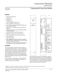
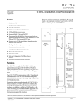
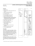
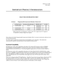
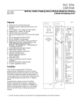
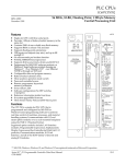
1
Coprocessor Modules
IC697PCM711
12
GFK-0164G
August 1997
Programmable Coprocessor Module
Coprocessor Modules
Programmable Coprocessor Module (IC697PCM711)
datasheet GFK-0164G
Features
•
•
•
•
•
•
•
•
•
•
•
•
•
•
•
Single slot Coprocessor
Dual Tasking
MegaBasict
CCM2 Protocol
12 Mhz, 80C186 microprocessor
90% of an IBMr AT performance
Up to 96 Kbytes battery-backed CMOS logic and
data memory on board
Supports up to 512 Kbytes optional expansion
memory
Programmed by IC647, IC640 or IBM-compatible
Personal Computer
Two RS-422/RS-485 or RS-232 serial ports
High performance access to PLC memory
Real time calendar clock synchronized to PLC
Reset pushbutton
Three Status LEDs
Soft Configuration (No dip switches or jumpers)
with MS-DOSr or Windowsr based programming
software configuration function
• Simultaneous communications on both ports at up
to 9.6 Kbaud, or up to 19.2 Kbaud individually.
Functions
a44716
OK
USER 1
USER 2
PCM 711
COPROCESSOR
ÎÎ
ÎÎ
Î
ÎÎ
ÎÎ
Î
ÎÎ
ÎÎ Î
ÎÎ
Î
ÎÎ
ÎÎ
Î
ÎÎ
Î
ÎÎ
Î
ÎÎ
Î
ÎÎ
Î
ÎÎ
Î
Î
ÎÎ
ÎÎÎ
Î
Î
ÎÎ
Î
ÎÎ
Î
ÎÎ
Î
ÎÎ
Î
ÎÎ
Î
ÎÎ
Î
ÎÎ
Î
ÎÎ
Î
ÎÎ
Î
ÎÎ
Î
ÎÎ
Î
ÎÎ
Î
ÎÎ
Î
ÎÎ
Î
ÎÎ
Î
ÎÎ
Î
Î
ÎÎ
Î
PCM 711
MODULE OK
USER 1
USER 2
ON = OK, ACTIVE
OR USER
PUSH TO RESTART
APPLICATION
PUSH AND HOLD TO
STOP AND RESET
BATTERY
CONNECTIONS
INSTALL NEW
BATTERY BEFORE
UNPLUGGING OLD
BATTERY. USE
IC697ACC701
PORT 1
RS–232 OR
RS–422/485
COMPATIBLE
MODULE FUNCTION
PROGRAMMABLE
COPROCESSOR,
COMMUNICA TIONS
OPTIONAL MEMORY
USE IC697MEM71
PORT 2
The Programmable Coprocessor Module (PCM) is a
Coprocessor to the PLC CPU. It can be programmed
to perform operator interface, real time computations,
data storage, data acquisition and data communications functions. It communicates with the PLC CPU
over the backplane and can access user and system
data using extensions to the powerful MegaBasic language. No application program support is required in
the PLC CPU.
Many PCMs can be supported in a single IC697 PLC
system and each can accommodate an optional expansion memory up to 512 Kbytes.
RS–232 OR
RS–422/485
COMPATIBLE
MODULE
IC697PCM711
LABEL
44A726758–203
Dual tasking allows running a MegaBasic program at
the same time the PCM is used as a communications
interface. Operation of the module may be initialized
by a pushbutton or by an attached PCM development
system. The status of the PCM is indicated by three
green LEDs on the front of the module.
tMegaBasic is a trademark of Christopher Cochran; rIBM is a registered trademark of International Business Machines Corporation.
r MS-DOS and Windows are registered trademarks of Microsoft Corporation.
Coprocessor Modules
2
GFK-0164G
August 1997
Programmable Coprocessor Module
Installation
Expansion Memory
• Installation should not be attempted without referring to the applicable Programmable Controller
Installation Manual (see reference 5).
The PCM can operate with or without an expansion
memory daughter board. The base memory on the
PCM board has up to 95 Kbytes user memory. The expansion memory daughter board permits expansion of
program/data memory by 64, 128, 256 or 512 Kbytes.
The battery which supports this memory is located on
the base board housing as shown in figure 2.
• Make sure rack power is off.
• Install expansion memory if required.
• Connect the battery to either of the battery connectors on the module. (See figure 2)
• Install in the rack. (See figure 1)
• Turn on power.
The module should power up and blink the top LED.
When the diagnostics have completed successfully the
top LED stays on.
PARALLEL
a42786g
ÎÎ
ÎÎ
Î
ÎÎ
Î
ÎÎ
Î
ÎÎ
Î
ÎÎ
ÎÎÎÎ
ÎÎ
ÎÎ
Î
ÎÎ
Î
ÎÎ
Î
ÎÎ
Î
ÎÎ
ÎÎÎÎ
Î
Î
ÎÎ
ÎÎ
Î
ÎÎ
Î
ÎÎ
Î
ÎÎ
Î
ÎÎ
ÎÎÎÎ
Î
Î
Î
Î
ÎÎÎÎÎÎ
ÎÎÎ
ÎÎÎ
ÎÎÎ
Î ÎÎÎÎÎÎÎÎ
Î
Î
ÎÎÎÎÎÎÎÎ
ÎÎ
ÎÎ
Î
ÎÎ
Î
ÎÎ
É
ÎÎ
Î
ÎÎ
ÎÎ
ÎÎ
Î
ÎÎ
ÎÎ
ÎÎÎ
ÎÎ
ÎÎÎ
ÎÎ
ÉÎÎ
ÎÎ
Î
ÎÎ
ÎÎ
ÎÎ
Î
ÎÎ
ÎÎ
Î
Î
É
Î
ÎÎ
ÎÎ
ÎÎ
Î
Î
Î
ÎÎ
ÎÎ
Î
ÎÎ
Î
ÎÎ
É
ÎÎ
Î
ÎÎ
ÎÎ
ÎÎ
Î
ÎÎÎÎÎÎ
ÎÎÎ
ÎÎÎ
ÉÎÎ
Î
ÎÎ
ÎÎ
Î
ÎÎ
Î
ÎÎ
Î
ÎÎ
Î
ÎÎ
ÎÎÎÎÎÎÎÎÎÎÎÎÎ
ÎÎÎ
Î
Î
ÎÎ
ÎÎ
Î
ÎÎ
Î
ÎÎ
Î
ÎÎ
Î
ÎÎ
Î
Î
Î
ÎÎ
ÎÎ
Î
ÎÎ
Î
ÎÎ
Î
ÎÎ
Î
ÎÎ
ÎÎÎÎÎÎ
ÎÎÎ
ÎÎÎ
ÎÎÎ
Î
ÎÎ
ÎÎ
Î
ÎÎ
Î
ÎÎ
Î
ÎÎ
Î
ÎÎ
ÎÎ
ÎÎ
Î
ÎÎ
ÎÎ
ÎÎ
Î
ÎÎÎ
ÎÎÎ
ÎÎÎ
ÎÎÎ
ÎÎ
Î
Î ÎÎ
ÎÎ
ÎÎ
Î
ÎÎ
Î
ÎÎ
Î
Î
ÎÎ
ÎÎ
ÎÎ
Î
Î
Î
Î
ÎÎ
ÎÎ
Î
ÎÎ
Î
ÎÎ
Î
ÎÎ
Î
ÎÎ
ÎÎ
ÎÎ
Î
ÎÎÎÎÎÎ
ÎÎÎ
ÎÎÎ
ÎÎÎ
Î
RACK 0
P
S
C B
P T
U M
a42759
PROGRAMMER
G
B
C
or
N
B
C
ONE
METER
IC66* I/O BUS (7500 FEET (2285 METERS) MAXIMUM)
OPEN
REPLACEMENT
BATTERY
CONNECTOR
CURRENTLY
INSTALLED
BATTERY
CONNECTOR
INSTALL NEW
BATTERY BEFORE
UNPLUGGING OLD
BATTERY. USE
IC697ACC701
RACK 6
NOTE
EXPANSION
MEMORY
BOARD
IC697MEM713
IC697MEM715
IC697MEM717
IC697MEM719
OPTIONAL MEMORY
USE IC697MEM71
RACK 7
PORT 2
B
R
M
CPU BRM BTM GBC/NBC PCM PS -
SELECTED CPU MODEL
BUS RECEIVER MODULE, BEM711
BUS TRANSMITTER MODULE, BEM713
BUS CONTROLLER, BEM731/734
PROGRAMMABLE COPROCESSOR MODULE, PCM711
POWER SUPPLY, PWR710/711/724/748
Figure 1. Typical PLC System Configuration (PCM
Shown in Rack 1)
RS–232 OR
RS–422/485
COMPATIBLE
PROGRAMMABLE
COPROCESSOR,
COMMUNICATIONS
RS–232 OR
RS–422/485
COMPATIBLE
MODULE
IC697PCM711
LABEL
44A726758–203
I/O TERMINATOR
(LAST RACK)
LEGEND
PORT 1
MODULE FUNCTION
IC66* I/O BUS (7500 FEET (2285 METERS) MAXIMUM)
ONE
METER
P
S
TOTAL LENGTH OF ALL INTERCONNECTING
CABLES FROM BTM TO LAST BRM IS 50 FEET
(15 METERS) MAXIMUM. ALL RACKS MUST BE
AT SAME GROUND POTENTIAL
(8 RACKS MAXIMUM).
USER 2
ON = OK, ACTIVE
OR USER
BATTERY
CONNECTIONS
IC66*
I/O BLOCK
G
B
C
or
N
B
C
MODULE OK
PUSH TO RESTART
APPLICATION.
PUSH AND HOLD TO
STOP AND RESET.
P
C
M
B
R
M
PCM 711
USER 1
RACK 1
B
R
M
ÎÎ
ÎÎ
Î
ÎÎÎ
ÎÎ
Î
ÎÎ
ÎÎ
Î
ÎÎ
Î
ÎÎ
Î
ÎÎ
ÎÎ
Î
ÎÎ
Î
Î
ÎÎ
ÎÎÎ
Î
Î
ÎÎ
Î
ÎÎ
Î
ÎÎ
Î
ÎÎ
Î
ÎÎ
Î
ÎÎ
Î
ÎÎ
Î
ÎÎ
Î
ÎÎ
Î
ÎÎ
Î
ÎÎ
Î
ÎÎ
Î
ÎÎ
Î
ÎÎ
Î
ÎÎ
Î
Î
ÎÎ
Î Î
ÎÎ
Î
PCM 711
Figure 2. Programmable Coprocessor Module - User
Details
Coprocessor Modules
3
GFK-0164G
August 1997
Programmable Coprocessor Module
Table 1. Port 1 or 2 - RS-232
Programming and Configuration
An IC647 or IC640 computer, or IBM-compatible PC,
XT, or AT computer with PCM Development Software
installed is connected to the top port of the PCM. The
default setting is 19,200 bps. The PCM Development
Software is used to configure the serial port parameters, to define the interface to the PLC CPU, to select
task functions and to program MegaBasic applications. The PCM parameters can also be configured
using MS-DOSr or Windowsr programming software. Consult reference 3 for details of operation.
ÎÎÎÎ
ÎÎÎÎ
ÎÎÎÎ
Î
ÎÎ
ÎÎÎÎ ÎÎ
ÎÎÎÎÎÎÎÎ
ÎÎÎÎÎÎÎÎ
Programmer
IC697CBL705
RS-232
(DEFAULT PORT)
Î
Î
GND
3PL
4PL
PIN
PIN
2
3
4
5
8
20
7
3
2
5
20
8
1
7
IC647 AND
IBM PS/2
25-PIN CONNECTOR
1
2
3
4
5
7
8
20
FUNCTION
Shield
Transmitted Data
Received Data
Request To Send
Clear To Send
Signal Ground
Data Carrier Detect
Data Terminal Ready
RXD
TXD
CTS
DTR
SHLD
GND
PCM
25-PIN
CONNECTOR
Figure 3. PCM Development System Connection to PCM
Serial Ports
Both ports are RS-232 and RS-422/RS-485 compatible.
Both ports acting simultaneously can each support up
to 9.6 Kbaud full duplex data communications, or they
can support up to 19.2 Kbaud individually.
SIGNAL
NAME
TD
RD
RTS
CTS
0V
DCD
DTR
I/O
Output
Input
Output
Input
Input
Output
Table 2. Port 1 or 2 - RS-422/RS-485
a43735
PCM
PCM
PROGRAMMING S/W
TXD
RXD
RTS
CTS
PIN
PIN
9
10
11
12
13
21
22
23
24
25
FUNCTION
Send Data (A)
Request to Send (A)
Clear to Send (A)
Termination for pin 13
Receive Data (A)
Send Data (B)
Request to Send (B)
Clear to Send (B)
Termination for pin 23
Receive Data (B)
SIGNAL
NAME
I/O
SD (A)
RTS (A)
CTS (A)
RD (A)
SD (B)
RST (B)
CTS (B)
RD (B)
Output
Output
Input
Input
Output
Output
Input
Input
Configuration
There are no user DIP switches or jumpers on this
board for configuration. However, the board must be
configured before operation using PCM Development
Software (See reference 3).
Status Indication
Three Status LEDs are available as shown in Figure 2.
The top LED indicates the condition of the module, the
bottom two LEDs may be assigned to a configured
function.
Port 1 (3PL) and Port 2 (4PL)
Controls
Connectors 3PL and 4PL contain signals for both RS-232
and RS-422/RS-485 types of communication circuits. The
pin-out for the RS-232 signals are per the RS-232 specification with an exception that pins not normally used for
RS-232 are used for RS-422/RS-485 signals. Details are
shown in tables 1 and 2.
One pushbutton is provided. Push and hold for less
than 5 seconds will restart an application. Push and
hold for more than 5 seconds and the module factory
default configuration will be installed (this action will
not clear memory but will permit communication with
the programmer using factory default settings).
Coprocessor Modules
4
GFK-0164G
August 1997
Programmable Coprocessor Module
Batteries
A lithium battery (IC697ACC701) is installed as shown
in figure 2. This battery maintains user memory when
power is removed. Be sure to install the new battery
before removing the old battery.
If during power-up diagnostics a low battery is detected
the Module OK LED (top) will not stay on. Specific indication of a low battery state is detailed in the PCM
Support Software User’s Manual.
Table 3. References
Reference
1
2
3
4
5
Title
ProgramingSoftware User ’s Manual
Programmable Controller Reference Manual
PCM Support Software User ’s Manual
MegaBasic Programming Language Reference Manual
Programmable Controller Installation Manual
Table 4. Specifications for IC697PCM711 [
Battery
Shelf life
Memory retention
10 years at 20°C (68°F)
6 months nominal without applied power.
Current required from 5V bus
1.0 amp
Serial Ports
RS-232/RS-422/RS-485 compatible
VME
System designed to support the VME standard C.1
[ Refer to GFK-0867B, or later for product standards and general specifications. If the PLC installation must comply with
supported standards, such as FCC or CE Directives, please refer to the Installation Requirements for Conformance to Standards, shipped with the PLC programming software, for additional guidelines.
Table 5. Ordering Information
Description
PCM, 12 Mhz, 20 Kbyte, Expandable
64 Kbyte CMOS Expansion Memory
128 Kbyte CMOS Expansion Memory
256 Kbyte CMOS Expansion Memory
512 Kbyte CMOS Expansion Memory
Lithium Battery
Catalog Number
IC697PCM711
IC697MEM713
IC697MEM715
IC697MEM717
IC697MEM719
IC697ACC701
Note: For Conformal Coat option, or Low Temperature Testing option please consult the
factory for price and availability.