1
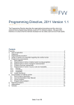
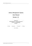
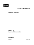
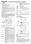
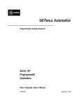
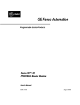
GE Fanuc Automation
Programmable Control Products
Series 90™-70
Demonstration Case
User’s Manual
GFK-0484A
June 1994
GFL-002
Warnings, Cautions, and Notes
as Used in this Publication
Warning
Warning notices are used in this publication to emphasize that hazardous voltages,
currents, temperatures, or other conditions that could cause personal injury exist in this
equipment or may be associated with its use.
In situations where inattention could cause either personal injury or damage to
equipment, a Warning notice is used.
Caution
Caution notices are used where equipment might be damaged if care is not taken.
Note
Notes merely call attention to information that is especially significant to understanding and
operating the equipment.
This document is based on information available at the time of its publication. While efforts
have been made to be accurate, the information contained herein does not purport to cover all
details or variations in hardware or software, nor to provide for every possible contingency in
connection with installation, operation, or maintenance. Features may be described herein
which are not present in all hardware and software systems. GE Fanuc Automation assumes no
obligation of notice to holders of this document with respect to changes subsequently made.
GE Fanuc Automation makes no representation or warranty, expressed, implied, or statutory
with respect to, and assumes no responsibility for the accuracy, completeness, sufficiency, or
usefulness of the information contained herein. No warranties of merchantability or fitness for
purpose shall apply.
The following are trademarks of GE Fanuc Automation North America, Inc.
Alarm Master
CIMPLICITY
CIMPLICITY 90–ADS
CIMSTAR
Field Control
FrameworX
GEnet
Genius
Helpmate
Logicmaster
Modelmaster
Motion Mate
ProLoop
PROMACRO
PowerMotion
PowerTRAC
Series 90
Series Five
Series One
Series Six
Series Three
VersaMax
VersaPoint
VersaPro
VuMaster
Workmaster
©Copyright 1989-2002 GE Fanuc Automation North America, Inc.
All Rights Reserved.
ii
Contents
Introduction .....................................................................................................................1-1
1.1 Basic Description ....................................................................................................... 1-1
1.2 Modes of Operation ................................................................................................... 1-2
1.3 Interfacing Options .................................................................................................... 1-2
Unpack/Install ...............................................................................................................2-1
2.1
2.2
2.3
2.4
2.5
2.6
Packing List ............................................................................................................... 2-1
Minimum Requirements ............................................................................................ 2-1
Physical Description .................................................................................................. 2-1
Pre-Installation Setup/Checkout ................................................................................ 2-2
Installation.................................................................................................................. 2-2
Power Up/Verification ............................................................................................... 2-2
Setup .........................................................................................................................................3-1
3.1 Possible Configurations ............................................................................................. 3-1
3.2 Other Possibilities ...................................................................................................... 3-2
Operation ............................................................................................................................4-1
4.1 PCM Demonstration .................................................................................................. 4-1
4.2 DEMO70 Ladder ....................................................................................................... 4-3
In Case of Trouble ....................................................................................................5-1
5.1
5.2
5.3
5.4
5.5
5.6
GFK-0484A
I/O Map...................................................................................................................... 5-1
Series 90–70 Configuration ....................................................................................... 5-2
Genius Demonstration Case Configuration ............................................................. 5-11
PCM Configuration.................................................................................................. 5-12
Program Files ........................................................................................................... 5-13
Cable Diagrams........................................................................................................ 5-14
iii
Chapter
Introduction
1
1.1 Basic Description
The GE Fanuc Series 90™-70 demonstration case is a versatile, portable device that is designed to
perform numerous control functions, either as an independent Programmable Logic Controller, or
in conjunction with several external simulation or control devices. It is based on the Series 90-70
Programmable Logic Controller, which consists of a rack capable of accommodating up to ten plug
in modules, including a wide-range power supply that operates on any voltage from 90V-132V for
115VAC or 185V-264V for 230VAC, and a powerful Central Processing Unit with expandable
Random Access Memory. An outline drawing of the case is shown below.
a43870
LOGIC
POWER
POWER
SUPPLY
GE Fan uc
SERIES 90-70
PROGRAMMABLE
CONTROLLER
OK
RUN
ENABLED
CPU 782
OK
PGMR ACTIVE
BUS ACTIVE
BUS
TRANSMITTER
OK
USER 1
USER 2
PROGRAMMABLE
COPROCESSOR
OK
CH 1 OK
EXP ACTIVE
GENIUS
BUS
CONTROLLER
1 CHANNEL
INPUT
24 VDC
OUTPUT
24/49 VDC,
0.5A
A1
A2
A3
A4
A5
A6
A7
A8
B1
B2
B3
B4
B5
B6
B7
B8
C1
C2
C3
C4
C5
C6
C7
C8
D1
D2
D3
D4
D5
D6
D7
D8
A1
A2
A3
A4
A5
A6
A7
A8
B1
B2
B3
B4
B5
B6
B7
B8
C1
C2
C3
C4
C5
C6
C7
C8
D1
D2
D3
D4
D5
D6
D7
D8
SLOT
GFK-0484A
OK
OK
INPUT
ANALOG
HIGH LEVEL
CHANNEL 1
OUTPUT
ANALOG (V)
HIGH LEVEL
CHANNEL 1
CHANNEL 2
CHANNEL 3
CHANNEL 2
CHANNEL 4
CHANNEL 5
CHANNEL 3
CHANNEL 6
CHANNEL 7
CHANNEL 4
CHANNEL 8
SLOT
SLOT
SLOT
1-1
1
Modules included with the demonstration case allow interfacing to common Input and Output
devices, such as thumbwheels, toggle switches, Light Emitting Diodes (LEDs), and a Binary Coded
Decimal (BCD) display. Additionally, the case contains several specialized modules which allow
operations with more sophisticated control devices.
An extremely versatile module, the Programmable Coprocessor Module (PCM), can be used for
data acquisition, data storage and retrieval, and operator interface applications, through the use of a
BASIC language interpreter called MegaBasic or C, and one of several user devices, such as
barcode readers, displays, serial printers, or personal computers. Furthermore, the PCM can be
used for communications to external Programmable Controllers in the Series 90 Family, or any
device capable of utilizing the GE Fanuc Series Six™ CCM protocol. Additionally, Analog Input
and Output modules are an integral part of the demonstration case, which can be used for
simulation or control functions with devices such as temperature, pressure, and flow transducers, or
motor drives, hydraulic actuators and signal meters.
Another module, perhaps the most dynamic and multipurpose module in the system, is the
Genius™ Bus Controller (GBC) module. The module is used primarily as the central control
device of the Genius I/O system, a high speed, serial communications link used for control of a
distributed I/O network. This system can also be interfaced to other devices, such as personal or
mainframe computers, for data logging, report generation or alternate I/O control applications.
Finally, a Bus Transmitter Module (BTM) is included in the case, which allows expansion to
another Series 90-70 rack for additional control and expanded Input and Output functions.
1.2 Modes of Operation
Because of the power built into the demonstration case, it is possible to use the system for much
more than product or sales-oriented displays, although these items were central themes in the
design of the case. The case can also be used quite effectively for control systems at local
Programmable Controller shows, and for system mockups at sales or customer locations. Since the
case is a fully functional operating system, it can be used for functional testing and simulation of
actual processes at customer sites, and is an invaluable aid in areas of training on both the
classroom and self-paced levels.
1.3 Interfacing Options
The demonstration case is capable of operating on its own, as an independent unit, without other
devices attached. Although the system does not have “real-world” devices directly attached, it is
useful in this stand-alone mode for program development, and basic familiarization and training.
In this mode, a programmer or other PC is used as the programming device, along with
Logicmaster™ 90-70, to enter and edit programs, and to monitor the operation of the Series 90-70
PLC.
The demonstration case is, however, much more powerful when interfacing to the GE Fanuc
Universal Simulator, a system which has all the devices necessary to demonstrate the functionality
of the modules in the Series 90-70 demonstration case. These devices include a gas plasma display
for connection to the PCM, Analog I/O potentiometers and meter, discrete devices like
thumbwheels, toggle switches, Light Emitting Diodes, and a BCD display. An added accessory of
the Universal Simulator is a 101-key keyboard, used for configuring, controlling, and developing
programs for the PCM in the Series 90-70 demonstration case. Furthermore, all cables for
1-2
Series 90™-70
Demonstration Case User’s Manual – June 1994
GFK-0484A
1
interfacing the Series 90-70 demonstration case to the Universal Simulator are included with the
Series 90-70 demonstration case.
The demonstration case can also be interfaced to a special Genius demonstration case, which
contains real-world input and output devices, and Genius I/O Blocks, one for discrete I/O, and one
for Analog I/O.
The Series 90-70 demonstration case can also be used in conjunction with the Series 90-30
demonstration case, to demonstrate the commonality of the Series 90 Family of PLCs, particularly
in areas like Genius Global Data transfers, and communications, using the PCM, which is common
to both PLCs. In the same area of communications, the PCM of either the 90-70 or the 90-30
demonstration case can be interfaced to other GE Fanuc PLCs, like the Series Six, Series Five™, or
Series One™, which all use a common communications protocol. The GE Fanuc Operator
Interface Unit (OIT) can also be used as an operator interface device, for message display, operator
control, or monitoring purposes with the PCM. For simple discrete input and output functions, the
Series 90-70 I/O modules can also be wired to a smaller, more compact simulator, called the Series
90-70 I/O Simulator.
In summary, the Series 90-70 demonstration case is a superior, functional demonstration system,
which can be interfaced to a wide variety of devices in order to accommodate the needs of the
individual in a multitude of situations.
GFK-0484A
Chapter 1 Introduction
1-3
1
1-4
Series 90™-70
Demonstration Case User’s Manual – June 1994
GFK-0484A
Chapter
Unpack/Install
2
2.1 Packing List
•
The package contains a fully assembled and tested Series 90–70 demonstration case with:
9 Slot Rack
55W Power Supply and Power Cord
782 CPU and 512K Memory
Bus Transmitter and Parallel Cable***
PCM and 512K Memory and RS232 Cable*
1 Channel Genius Bus Controller
24V Input 32 pt Module and Cable**
24V Output 32 pt Module and Cable**
Analog Input Module and Cable*
Analog Output Module and Cable*
Blank Slot
* Cable to be used with the Universal Simulator
** Cable to be used with the Universal Simulator or the Series 90–70 I/O Simulator
*** Cable to be used with the programmer
•
A complete set of Series 90–70 Instruction Manuals and Data Sheets.
•
A 3.5 inch backup disk with DEMO70, TEST70 ladder programs and PCM Program and Text
files.
2.2 Minimum Requirements
The Series 90–70 demonstration case can be used alone or with almost any combination of other
GE Fanuc equipment depending on the interests of the audience.
2.3 Physical Description
The Series 90–70 demonstration case is contained in an aluminum case for easy portability. In the
case is a standard rear mount 9 slot rack, populated with the modules listed above. It has been fully
tested with the Universal Simulator and comes loaded with the standard ladder and PCM
demonstration programs.
GFK-0484A
2-1
2
2.4 Pre-Installation Setup/Checkout
Check for shipping damage and make sure all the modules are seated in the rack.
2.5 Installation
•
Connect the cables to any other equipment to be used, such as the Universal Simulator, Genius
demonstration case, and programmer.
The cables to the Universal Simulator are labeled as to which plug they connect to and are of
the easy snap on/off variety that do not require a screw driver.
•
Remove the keyboard from the lid of the Universal Simulator case and plug it into the
keyboard connector.
•
Make sure the 115 to 230 selector switch is set to the proper position.
•
Connect all equipment to an appropriate power source.
2.6 Power Up/Verification
When power is applied to the Series 90–70, the Logic Power light should come on and the top light
on the CPU, PCM, and Bus Controller should flash for a while and then stay on along with the top
light of the Bus Transmitter.
The Run and Enabled lights on the CPU should reflect the state of the Run/Stop switch.
The Pgmr Active light on the Bus Transmitter should be on when Logicmaster 90 is active on the
programmer.
The User 1 light on the PCM should flash when the screen on the Universal Simulator is being
updated.
The CH 1 OK light on the Genius Bus Controller should be on.
The lights on the Input and Output modules may or may not be on depending on the state of the
simulator switches and the ladder program.
The OK light on the Analog Input and Output modules should be on.
If a Universal Simulator is connected and turned on the screen should show the main menu with 7
possible selections.
If a Genius demonstration case is connected and turned on, and configured according to the
instructions in this manual, the Unit OK light on both blocks should be on. If the CPU is in Run
mode, the I/O Enabled light should be on for both blocks.
2-2
Series 90™-70
Demonstration Case User’s Manual – June 1994
GFK-0484A
Chapter
Setup
3
3.1 Possible Configurations
There are many possible system configurations possible. The standard demonstration programs
assume the following configuration:
(Reserved for High Speed Counter)
UNIVERSAL
SIMULATOR
SERIES 90–70
DEMO CASE
GENIUS
DEMO CASE
PROGRAMMER
Suggested Configuration
The Universal Simulator is used to show the power of the PCM and digital and analog inputs and
outputs.
The Genius demonstration case is used to show Genius digital and analog inputs and outputs and
Genius diagnostics.
The programmer is used to show Logicmaster 90–70 and the Series 90–70 instruction set.
GFK-0484A
3-1
3
3.2 Other Possibilities
The programmer screen or a Monochrome OIT could be used in place of the Universal Simulator
screen. Using a programmer screen also allows use of an overhead projector for larger audiences
using a VGA display device.
A Series 90–70 I/O Simulator could be used in place of the Universal Simulator switches and lights
if the audience does not require the screen or analog I/O.
A Series 90–30 demonstration case could be connected to the Genius Bus to show Genius Global
Communication. If this is done, some configuration and ladder changes will have to be made in the
Series 90–70.
3-2
Series 90™-70
Demonstration Case User’s Manual – June 1994
GFK-0484A
Chapter
Operation
4
4.1 PCM Demonstration
The PCM Demonstration contains a Main Menu with several possible selections. There are two
selections, one for the Series 90–30 and one for the Series 90–70, that contain a scrolling window
of many of the significant features of each control. These can be used as the basis for many
product presentations. There is a screen that lists many of the Logicmaster 90 programming and
configuration features. Next there is a set of three application screens showing Manufacturing,
Process, and Material Handling. There is a Fault Table screen that shows the I/O Fault Table from
Logicmaster 90. Also there is a PCM animation screen that shows the speed of processing and
screen update capability of the PCM. Lastly there is a selection to allow the customizing of the
feature screens with the audience name.
The PCM Demonstration can be operated without further instructions by just reading the prompts
on the screen. But here are some hints that will make things go smoother:
1.
The first thing to do to prepare for a demonstration is to go to number 7 on the main menu and
enter the audience name. This is not required but it adds a nice touch. You can put in anything
you want up to 30 characters. Some samples are:
TO R P COLLINS and STAFF
JOE’S CAR
ACME AND
TO ALL OUR
TO THE PODUNK INDUSTRIAL
Whatever you put in will then show up centered on the upper part of the two features screens.
This field is cleared whenever item 7 is selected.
2.
GFK-0484A
Select the Series 90–70 Features screen. Every 5 seconds a new feature scrolls into the scroll
window. To pause on a feature, hit the space bar. This allows a discussion of any topic for as
long as required. A second hit of the space bar advances to the next feature. The space bar can
4-1
4
also be used to skip a feature that is of little interest. The scrolling feature list will repeat
continuously if left undisturbed.
The Escape or Enter keys will always bring you back to the Main Menu.
3.
The Logicmaster Features screen is a static screen showing a list of Logicmaster programming
and configuration features.
4.
The Application Demonstration screen shows a sub menu of sample industry applications. All
of these screens show screen animation and screen update speed, PCM to CPU communication
and the graphics possibilities of the PCM and MegaBasic. A description of each application
follows:
A. Manufacturing – Shows a simulated Paint Shop with cars moving along the conveyor,
going through one of two paint booths and then through the baking oven. The speed of
the cars is controlled by the number in the Universal Simulator thumbwheel switches. The
smaller the number, the faster the cars move. Turning on switch 9 on the Universal
Simulator simulates a fan failure, shuts the line down, and displays an error message.
B. Process – Shows a line of simulated Wine Presses with various valves that can be
controlled by switches 1 through 6 on the Universal Simulator. Switch 1 is the master
control and must be on in order to get any wine. Then switches 2, 3, 4, and 5 will control
the number of presses that receive grapes to be crushed. With switch 1 and a combination
of switches 2 – 5 on you will see the wine dribble out the lower pipe.
C. Material Handling – Shows a Tank Farm with 8 tanks that you can use to hold your wine.
Each tank has an inlet/discharge valve that you can control using switches 1 through 16 on
the Universal Simulator. Each valve can be closed, half open, or full open. Each tank has
a level indicator and when any tank reaches an overflow condition, an error message is
displayed. If any tank is left unattended with its valve open, it will cycle from empty to
full and back to empty.
4-2
5.
The Fault Table screen shows a simulation of the Logicmaster I/O Fault Table. A future
project is to update this screen from the CPU.
6.
The PCM Animation screen shows 8 bar graphs all being updated in a random manor from 8
independent timed interrupts in the PCM. This screen shows the tremendous speed of the
PCM, and its ability to keep screen information current.
Series 90™-70
Demonstration Case User’s Manual – June 1994
GFK-0484A
4
7.
The structure of the PCM demonstration program is shown below:
BASIC.PGM
VT100_5.CRN*
*Accessed from
each file.
S90_DEMO.CRN
FEATUR30.CRN
FEATUR70.CRN
LM90TU.CRN
SYSDEMO.CRN
MANUFACT.CRN
PROCESS.CRN
FLTTBL.CRN
GRAPH1.CRN
MAT_HAND.CRN
4.2 DEMO70 Ladder
The DEMO70 ladder program shows many of the features and capabilities of the Series 90–70
PLC. First, it is an example of structured programming, in that almost all of the logic is contained
in Program Blocks. Second, it contains a working sample of each ladder instruction and function
block. These samples are grouped in program sub blocks according to their Logicmaster 90
function key groups. Third, the Genius demonstration case can be used not only to show Genius
I/O but also Genius Diagnostics. You can force Genius faults and show the results on the
Logicmaster I/O Fault Table. And fourth, you can use the programmer and Logicmaster 90–70 to
show the programming and configuration software and the on line monitoring of the program and
status tables.
The program contains 19 program blocks of which 13 are called from the MANUAL block.
These contain the sample instructions.
When the program first starts, the FIRST SCAN contact forces it into Manual mode and the
MANUAL program block is activated. Move the cursor to the MANUAL block and zoom into
it using F10. Now you can interrogate each of the blocks containing the sample instructions by
simply dialing up its number on the Universal Simulator thumbwheel and toggling switch 16.
Then zoom into that block using F10. There are 11 blocks numbered as follows:
1) RELAY, 2) TMR,
6) B ITOP, 7) DATAMV,
3) CTR,
4) MATH,
8) TABLES, 9) CONVRT,
5) RELATN,
10) CONTRL, and 11) SYSREFS.
There is one more block (without a number) called SETUP which is used for Manual
operations and for housekeeping for the rest of the blocks. It is activated by dialing 0 on the
thumbwheel and toggling switch 16. This will connect all 16 switches to the lights. If switch
1 is on and 2 is off the -10 to +10 pot is connected to the meter. If switch 1 is off and 2 is on
GFK-0484A
Chapter 4 Operation
4-3
4
the 0 to +10 pot is connected to the meter. If switch 3 is on the -10 to +10 pot is connected to
the BCD display.
Once activated as described above, each of the sample instruction blocks can be demonstrated
by just reading the logic and turning on the switches called for. The comment at the beginning
of each program block contains instructions for demonstrating the logic in that block. Use F10
to zoom into a comment after placing the cursor on that rung. In each block, toggling switch
15 will clear the working %R, %P, and %Q tables so you can start over with a clean slate.
Once you have made it through all the Manual features of the ladder program, you are ready to put
it into Auto mode. Momentarily activate the Genius demonstration case limit switch to set the
Auto mode. Operating the Genius demonstration case metal detector (input #7) or cycling through
Run–Stop–Run with the CPU switch takes the program out of auto mode.
When in the Auto mode, the lights on the Universal Simulator are cleverly bounced around by the
LIGHTS program block with the help of the DISPLAY program block. The LOG program block
counts the number of times the lights shift back and forth and puts the number on the BCD display.
The thumbwheel switch is used to control the speed of the shifting. The smaller the number, the
faster the lights will shift.
In any mode the GENIUS program block does the following:
4-4
1.
The value from Analog input 1 is compared against a high and low value and the result is used
to control the 3 lamps on the Genius Demonstration Case: yellow for low alarm, green for no
alarm, and red for high alarm.
2.
The relay is activated when Analog input #1 remains high for longer than 5 seconds.
3.
The Analog values for inputs 1 and 2 are each copied to the corresponding Analog outputs and
thus to the two meters on the Genius demonstration case.
4.
Each of the Fault switches on the Genius demonstration case can be used to create faults in the
Logicmaster I/O Fault Table. (Remember the relay can not cause a fault unless it is
energized.)
Series 90™-70
Demonstration Case User’s Manual – June 1994
GFK-0484A
Chapter In Case of Trouble
5
5.1 I/O Map
This I/O Map has been used for all standard demonstration programs. It should be used as a
base for all future developments.
GFK-0484
5-1
5
5.2 Series 90-70 Configuration
CPU 782
653
6
5-2
Series 90-70 Demonstration Case User’s Manual - June 1994
GFK-0484
5
IC697CPU782
IC697MEM735
, FLOATING
16
512
735
GFK-0484
Chapter 1 In Case of Trouble
5-3
5
IC697MDL653
5-4
Series 90-70 Demonstration Case User’s Manual - June 1994
GFK-0484
5
GFK-0484
Chapter 1 In Case of Trouble
5-5
5
5-6
Series 90-70 Demonstration Case User’s Manual - June 1994
GFK-0484
5
101
GFK-0484
Chapter 1 In Case of Trouble
5-7
5
IC660BBD101
5-8
Series 90-70 Demonstration Case User’s Manual - June 1994
GFK-0484
5
GFK-0484
Chapter 1 In Case of Trouble
5-9
5
CPU MEMORY CONFIGURATION FOR MODEL 771 CPU:
Discrete Input
Discrete Output
(%I)
(%Q)
Internal Discrete
(%M)
2048
2048
Bytes
By-
4096
By-
512 Bytes
256
By-
tes
tes
System Use
Temporary Status
(%S)
(%T)
tes
–––
–––
TOTAL DISCRETE MEMORY:
Analog Input
8960 Bytes
(%AI)
64
Wor
64
Wor
1024
Wor
ds
Analog Output
(%AQ)
ds
Register Memory
(%R)
ds
TOTAL LOGIC MEMORY
521344
CPU MEMORY TOTAL
524288 Bytes
POINT FAULT REFERENCE
Bytes
ENABLED
FAULT CATEGORY CONFIGURATION:
Loss of or Missing Rack
Loss of or Missing IOC
Loss of or Missing I/O Module
Loss of or Missing Option Module
System Bus Failure
IOC Fault (I/O Bus Fault)
System Config Mismatch
5-10
Series 90-70 Demonstration Case User’s Manual - June 1994
D
D
D
D
F
F
D
GFK-0484
5
5.3 Genius Demonstration Case Configuration
DISCRETE BLOCK
Baud Rate
Block Number
Circuit References
Block Type
Configuration Protect
Pulse Test
Input Filter Time
Circuit Configuration
Report Fault
Hold Last State
Output Default
Report No Load
Overload Shutdown*
BSM Present
CPU Redundancy
153.6K ST
1
49 to 56 (Don’t care)
OI
Disabled
Enabled
50 ms
1 2 3 4 5 6
IT
OI
OI
OI
I
I
Yes
No
Off
1
2
3
5
6
7
X
Y
N
N
X
X
Yes
No
No
7 8
OI
I
4
8
N
X
ANALOG BLOCK
Baud Rate
Block Number
Circuit References
Configuration Protect
Report Fault
Current/Voltage Range
Scaling Points
Input Filter Time
High/Low Alarms
Alarm Input Mode
Hold Last State
Output Default
BSM Present
CPU Redundancy
153.6K ST
2
49 to 54 (Don’t care)
Disabled
1
2
3
4
5
6
Y
Y
N
N
Y
Y
Input Channels 1&2 4–20ma
Output Channels –10 to +10
Inputs +/–10,000 Eng. Units
Inputs 0 / 4,095 Raw Counts
Outputs +/–10,000 Eng. Units
Outputs +/–10,000 Raw Counts
128ms
+/–10,000
No
No
0
No
No
Caution
*DO NOT DISABLE THE OVERLOAD SHUTDOWN. The temperature
sensors for the Genius blocks are disabled. Excessive heat may build up in
the demonstration case if an overload condition exists for an extended
period of time.
GFK-0484
Chapter 1 In Case of Trouble
5-11
5
5.4 PCM Configuration
EDIT MEGABASIC CONFIGURATION DATA
Enable Megabasic:
Start MB on Soft Reset:
Program to Run at Reset:
User Program I/O
Interpreter Ver to Use:
Priority:
MegaBasic Command Line:
Allocated Data Size:
YES
YES
RAM:BASIC.PGM
Input: NULL
Output: NULL
Error: COM1
DEV
6
blank
90
EDIT SERIAL PORT 1 (COM1:)
Interface:
Data Rate:
Parity:
Flow Control:
Stop Bits:
Bits/Char:
RS232
19200
NONE
SOFTWARE
1
8
EDIT SERIAL PORT 2 (COM2:)
This Data is IGNORED because CCM is Enabled on This Port.
EDIT CCM CONFIGURATION DATA FOR PORT 1
Enable CCM on Port:
NO
EDIT CCM CONFIGURATION DATA FOR PORT 2
Enable CCM on Port:
CCM CPU ID:
Mode:
Turnaround Delay:
Timeout:
Retry Count:
Interface:
Data Rate:
Parity:
Flow Control:
Priority:
YES
1
MASTER
100ms
LONG
NORMAL
RS485
9600 bps
NONE
NONE
5
All other settings are set to the Default values.
5-12
Series 90-70 Demonstration Case User’s Manual - June 1994
GFK-0484
5
5.5 Program Files
A 3.5 inch disk is included with each Series 90-70 demonstration case that includes the
following directories:
DEMO70
Logicmaster files with the demonstration ladder.
TEST70
Logicmaster files used to test the cables between the Series 90-70
demonstration case and the Universal Simulator.
PCM
MegaBasic files for the PCM. The .TXT files in PCM70 can be used for a
listing of the programs.
The files that are loaded on the PCM are in DEM70.PCM:
BASIC.PGM
S90_DEMO.CRN
FEATUR30.CRN
FEATUR70.CRN
LM90TU.CRN
SYSDEMO.CRN
MANUFACT.CRN
PROCESS.CRN
MAT_HAND.CRN
FLTTBL.CRN
GRAPH1.CRN
VT100_5.CRN
UCDF.CDF
Configuration
5.6 Cable Diagrams
DISPLAY
25 Pin
2
3
4
5
7
Female
25 Pin Male
––––––––––––––––––––––––––– 3
––––––––––––––––––––––––––– 2
––––––––––––––––––––––––––– 5
––––––––––––––––––––––––––– 4
shield
shield 7
ENCODER
9 Pin Male
High Speed Counter
1 ––––––––––––––––––––––––––– Channel A
2 ––––––––––––––––––––––––––– Channel B
7 shield
METER
9 Pin Female
Analog Output
3 ––––––––––––––––––––––––––– 3
5 ––––––––––––––––––––––––––– 5
7 shield
POTS
9 Pin Male
Analog Input
3 ––––––––––––––––––––––––––– 3
5 ––––––––––––––––––––––––––– 5
7 shield
4 ––––––––––––––––––––––––––– 4
GFK-0484
Chapter 1 In Case of Trouble
5-13
5
6 ––––––––––––––––––––––––––– 6
8 shield
INPUT
37
1
9
17
25
35
Pin Male
24V Input
thru 8 –––––––––––––––––––– 2 thru 9
thru 16 –––––––––––––––––– 12 thru 19
thru 24 –––––––––––––––––– 22 thru 29
thru 32 –––––––––––––––––– 32 thru 39
–––––––––––––––––––––––––– 40,30,20,10
OUTPUT
37
1
9
17
25
33
36
5-14
Pin Male
24V Output
thru 8 –––––––––––––––––––– 2 thru 9
thru 16 –––––––––––––––––– 12 thru 19
thru 24 –––––––––––––––––– 22 thru 29
thru 32 –––––––––––––––––– 32 thru 39
–––––––––––––––––––––––––– 31,21,11,01
–––––––––––––––––––––––––– 40,30,20,10
Series 90-70 Demonstration Case User’s Manual - June 1994
GFK-0484