1
X-BAR-PRO
Instruction Manual
Product Description
This is a waterproof LED lighting bar with fantastic lighting effect. It's RGB, WW, CW and Blue LEDs are
available for user selection. We can also provide you 3 series X-BAR-PROs with different sizes as your desire.
Such as X-BAR-PRO-500; X-BAR-PRO-1000 series (X-BAR-PRO-625 ,X-BAR-PRO-875, X-BAR-PRO1000);X-BAR-PRO-1500 Series (X-BAR-PRO-1250,X-BAR-PRO-1500). More X-BAR-PRO can be
connected for use. A proper system configuration must be established before performing this unit into
application. Please read this manual thoroughly for operation guide in details.
Programming
1. Slave Control Mode
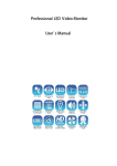
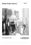
A LED Setup Tool (depicted here) _XB-R1 is required to program the
X-BAR-PROs Lighting. For further information, please refer to its
accompanying manual. There are different Work Modes for Slave
Control according to the desired X-BAR-PRO with different sizes
as you desire. Please refer to followings:
X-BAR-PRO-500
A LED Setup Tool(XB-R1)
(Sold separately)
For X-BAR-PRO-500, there are 9 Work Modes in Slave Control, Work Modes include:
4 RGB Mode
2 RGB Mode
1 RGB Mode
4 C&B Mode
2 C&B Mode
1 C&B Mode
4 COLOR Mode
2 COLOR Mode
1 COLOR Mode
X-BAR-PRO-1000 Series include 3 different sizes:
X-BAR-PRO-625( 5 RGB 625mm)
X-BAR-PRO-875 ( 7 RGB 875mm)
X-BAR-PRO-1000 ( 8 RGB 1000mm)
(X-Bar-PRO-1000-Blue is consulted by factory)
For X-BAR-PRO-1000 Series, there are 12 Work Modes in Slave Control, Work Modes include:
8 RGB Mode
8 C&B Mode
8 COLOR Mode
4 RGB Mode
4 C&B Mode
4 COLOR Mode
2 RGB Mode
2 C&B Mode
2 COLOR Mode
1 RGB Mode
1 C&B Mode
1 COLOR Mode
NOTE: the functions of X-BAR-PRO-1000 of Blue LEDs are same with X-Bar-PRO-1000 of RGB LEDs.
X-BAR-PRO-1500 Series include 2 different sizes:
X-BAR-PRO-1250( 10 RGB 1250mm)
X-BAR-PRO-1500( 12 RGB 1500mm)
For X-BAR-PRO-1500 Series, there are 18 Work Modes in Slave Control, Work Modes include:
12 RGB Mode
6 RGB Mode
4 RGB Mode
3 RGB Mode
2 RGB Mode
1 RGB Mode
12 C&B Mode
6 C&B Mode
4 C&B Mode
3 C&B Mode
2 C&B Mode
1 C&B Mode
12 COLOR Mode
6 COLOR Mode
4 COLOR Mode
3 COLOR Mode
2 COLOR Mode
1 COLOR Mode
*NOTE: Please refer to User Manual on the connected Setup Controller
C&B=Color And Bright
24-004-2800-00
Rev1.0
Take X-BAR-PRO-1000 as an example, the followings are 12 Work Modes and Parameter
Details for Slave Control.
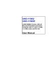
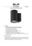
MODE-1
Standard mode(24 channels in total=8x3 channels)
8 RGB mode: has 8 groups with RGB output, of which each group consists of 3 channels(24 channels in total).
Channel 1-24 / Group 1-8
Color (R/G/B) Output 1
Output 2 Output 3 Output 4 Output 5 Output 6 Output 7 Output 8
Group 1 Group 2 Group 3 Group 4 Group 5 Group 6 Group 7 Group 8
Red
Blue
MODE-2
1
4
7
10
13
16
19
22
2
5
8
11
14
17
20
23
3
6
9
12
15
18
21
24
Color and intensity mode(16 channels in total=8x2 channels)
8 C&B mode: has 8 groups with color and intensity C&B output, of which each group consists of 2 channels
(16 channels in total).
Channel 1-16 / Group 1-8
C&B
MODE-3
Output 1 Output 2 Output 3 Output 4 Output 5 Output 6 Output 7 Output 8
Group 1 Group 2 Group 3 Group 4 Group 5 Group 6 Group 7 Group 8
Color
1
3
5
7
9
11
13
15
Brightness
2
4
6
8
10
12
14
16
Color mode(8 channels in total=8x2 channels)
(3) 8 COLOR mode: has 8 groups with Color control, of which each group consists of 1 channel
(8 channels in total). The brightness is always 100% in this mode.
Channel 1-8 / Group 1-8
C&B
Color
Output 1 Output 2 Output 3 Output 4 Output 5 Output 6 Output 7 Output 8
Group 1 Group 2 Group 3 Group 4 Group 5 Group 6 Group 7 Group 8
1
2
4
3
6
5
7
8
Brightness 100% 100% 100% 100% 100% 100% 100% 100%
MODE-4
Patch mode RGB of 24 outputs---->12 outputs(4x3 channels)
4 RGB mode: in this mode, 2 outputs are patched. The driver has 4 identical outputs distributed over 8 groups.
Channel 1-12 / Group 1-4
Color (R/G/B) Output 1-2
Output 3-4 Output 5-6 Output 7-8
Group 1 Group 2 Group 3 Group 4
Red
Blue
MODE-5
1
4
7
10
2
5
8
11
3
6
9
12
Patch mode C&B of 16 outputs---->8 outputs(4x2 channels)
4 C&B mode: has 4 groups with C&B output, of which each group consists of 2 outputs that are
controlled by 2 channels(8 channels ly).
Channel 1-8 / Group 1-4
C&B
Output 1-2 Output 3-4 Output 5-6 Output 7-8
Group 1 Group 2 Group 3 Group 4
Color
1
3
5
7
Brightness
2
4
6
8
-Page 2-
MODE-6
Patch mode Color of 8 outputs---->4 outputs(4x1 channels)
4 COLOR mode: has 4 groups with Color control, of which each group consists of 2 outputs that are
controlled by 1 channel(4 channels in total). The brightness is always 100% in this mode.
Channel 1-4 / Group 1-4
C&B
Output 1-2 Output 3-4 Output 5-6 Output 7-8
Group 1 Group 2 Group 3 Group 4
Color
1
2
4
3
Brightness 100% 100% 100% 100%
MODE-7
Patch mode RGB of 24 outputs---->6 outputs(2x3 channels)
2 RGB mode: in this mode, 4 outputs are patched. The driver has 12 identical outputs distributed over 2 groups.
Channel 1-6
Color (R/G/B) Output 1-4
Group 2
1
4
2
5
3
6
Red
Blue
MODE-8
Output 5-8
Group 1
Patch mode C&B of 16 outputs---->4 outputs(2x2 channels)
2 C&B mode: has 2 groups with C&B output, of which each group consists of 4 outputs that are controlled
by 2 channels (4 channels in total).
Channel 1-4/Group1-2
C&B
MODE-9
Output 1-4
Output 5-8
Group 1
Group 2
Color
1
3
Brightness
2
4
Patch mode Color of 8 outputs---> 2 outputs(2x1 channel)
2 COLOR mode: has 2 groups with Color control, of which each group consists of 2 outputs that are controlled
by 1 channel (2 channels in total). The brightness is always 100% in this mode.
Channel 1-2/Group1-2
C&B
Output 1-4
Output 5-8
Group 1
Group 2
Color
1
2
Brightness
100%
100%
MODE-10 Patch mode RGB of 24 outputs---->3 outputs(3x1 channels)
1 RGB mode: in this mode, 8 outputs are patched. The driver has 24 identical outputs distributed over 1 group.
Color (R/G/B)
Red
Channel 1-3
Group 1/
Output 1-8
1
2
Blue
3
-Page 3-
MODE-11 Patch mode C&B of 16 outputs---->2 outputs(2x1 channels)
1 C&B mode: has 1 group with C&B output, which consists of 8 outputs that are controlled by 2 channels.
Channel 1-2
C&B
Group 1/
Output 1-8
Color
1
Brightness
2
MODE-12 Patch mode Color of 8 outputs---->1 outputs(1x1 channels)
1 COLOR mode: has 1 group with Color control, which consists of 1 output that is controlled by
1 channel. The brightness is always 100%.
Channel 1
C&B
Group 1/
Output 1-8
Color
1
Brightness
100%
NOTE:
1. The Glide Effect function can be switched on(YES) or off(NO). The transition from one level to another is
smoother when this function is switched on.
2. When this function is switched off, the lighting intensity will changed from one level to another abruptly.(thus,
when a quick lighting effect is required, the Guide Effect function should be switched off.)
3. If the DMX signal is interrupted, the driver will keep the last received DMX signal(information) until the driver
is switched off or a new and valid DMX signal is sent.
2.Master Control
AUTO mode and MANUAL mode are for Master Control. Relevant functions are as below:
(1) AUTO mode:
Preset programs:1-10 programs and "AUTO" program ("AUTO"program is the sequential
running of these1-10 programs.)
Auto Speed: 1~100.
(2) MANUAL mode:
Auto Fadetime: 0%~100%.
BLUE/ Duration: 0%~100%.
RED / Speed : 0%~100%.
GREEN / Dimmer: 0%~100%.
NOTE:
1. The LEDs will turn red in Slave Control mode.
The LEDs will give responding sensitive when the parameters are adjusted in Master Control.
2. If the LED is not selected in "Setup with answer", it will turn red.
If the LED is not selected in :Setup no answer", it will switch off.
When the user confirms the settings of the LED products, the LEDs will flash momentarily to confirm that the
setting have been saved.
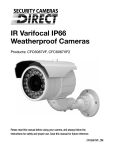
Schematic Diagram
X-BAR-PRO
Holding Clamp
Over View
IP65 air relief
500mm/875mm/1000mm/1250mm/1500mm
Power/Data Output
(Female Connector)
Power/Data Input
(Male Connector)
Side View
Accessories
Holding Clamp
End View
M4 Screw
Holding clamp- 2pcs holding clamps per X-BAR-PRO.
NOTE: M4 hexagon screw is used to tighten and secure your X-Bar-PROs.
-Page 4-
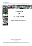
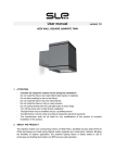
Appendix: System Connection
1pcs power supply(24VDC,6.5A) and 1pcs
Power/Data starter cable can drive up to
7pcs X-BAR-PRO-1500
8pcs X-BAR-PRO-1250
10pcs X-BAR-PRO-1000
A)
12pcs X-BAR-PRO-875
6.5
C,
D
V
20pcs X-BAR-PRO 500
24
ly(
8p
cs
X
AR
-B
PR
1
O-
0
25
pe
rp
e
ow
rs
up
8th.
p
PC c/w DMX
Software
1st.
AC230V
Fuse Spur Unit
Control Room
X-DRIVER 48
DMX
Universes 2
DMX Booster
D+
D-
GND
GND
24VDC
D+
D-
GND
GND
24VDC
D+
D-
GND
GND
24VDC
D+
D-
GND
GND
24VDC
D+
D-
GND
GND
24VDC
Power Supply
24VDC,6.5A
Power Supply
24VDC,6.5A
Power Supply
24VDC,6.5A
Power Supply
24VDC,6.5A
Power Supply
24VDC,6.5A
DMX
Universes 1
DMX Booster
48 DMX
Universes
CONTROL 1
AC 230V 1A
CONTROL 2
DMX CONTROLLER
Remark: Add signal repeater if data cable over 100m
Power
1000mm
DMX
D+
D-
GND
GND
24VDC
AC 230V 1A
Power Supply
24VDC,6.5A
24VDC
GND
+
GND
DD+
Power/Data Starter cable per 8pcs X-BAR-PRO
2 x Holding clamp
2 x M4 Screw
The Power/Data Cable is used to connect your X-BAR-PROs with the power device and the DMX Controller.
Please notice its above pin assignment.
*Note:
Before installation, make sure the end with built-in IP 65 air relief should be downward.
As the above illustration shows, how many X-BAR-PROs that 1pcs power supply and 1pcs power/data
cable can drive depends on the current of the power supply.
Only when using the same series in link, the Master X-BAR-PRO can control the activity of Slave X-BARPROs.
In case you have to use different series in link, you can control the activity of all desired X-BAR-PROs by
an external DMX Controller.
Please connect the power/data cable and the DMX controller correctly indicated by the above illustration.
*Special Note:
For reducing signal errors and avoiding signal transmission problems and interference, it is always
advisable to connect 120 ohm impedance DMX signal cable and DMX terminator for signal connection.
X-BAR-PRO applies to graphical display. When its working Gross Power exceeds 80% of the
Maximum Power, the duration should not exceed 30 minutes.Otherwise the product capability
especially the operation life will be affected.
-Page 5-
Technical Specifications
Power Requirement...........................................................................24VDC, 250mA for X-BAR-Pro-500
...........................................24VDC, 400mA for X-BAR-Pro-875
.........................................24VDC, 450mA for X-BAR-Pro-1000
.........................................24VDC, 550mA for X-BAR-Pro-1250
.........................................24VDC, 650mA for X-BAR-Pro-1500
Lighting source............................................................................................RGB, WW,CW or Blue LEDs
IP rating............................................................................................................................................IP 65
Dimensions................................................................................................................................ =35mm
Accessories(Included)...............................................................................................1xPower/Data cable
2xHolding Clamps per X-BAR-PRO
Caution!
All rights reserved. No part of this manual included with this product can be reproduced or transmitted
in any form, by any means or for any purpose without authorized permission.
Improvements on specifications, design and this manual are subject to change without any prior notice.
-Page 6-