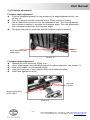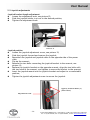
1
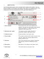
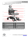
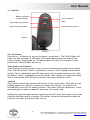
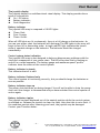
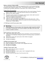
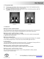
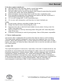
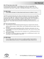
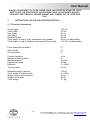
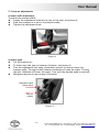
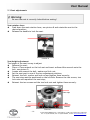
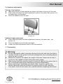
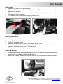
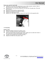
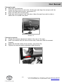
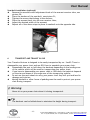
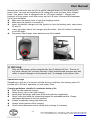
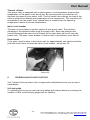
User Manual BEFORE USING YOUR NEW TRAVELUX VENTURE POWER CHAIR YOU MUST READ AND FULLY UNDERSTAND THIS USER MANUAL General information You have just purchased an Van Os Medical UK ltd. power chair and we want to thank you for the confidence in our Travelux products. The power chair is a quality product. The policy of Van Os Medical UK ltd. is to continually improve the quality and reliability of our products. We reserve the right, therefore without prior notification, to alter this guide. It is important that your guide for the use is read carefully. The manual contains important information about the safe use and maintenance of your power chair. We recommend that you keep this guide, it is also your proof of warranty and you will find it useful for referring to it at a later date. The safety instructions in this guide are general guidelines that must be seen as broad guidelines. Your new power chair requires frequent maintenance, much of which you can do yourself. We advise you to take your power chair once a year to be inspected by a professional. Caution! In this guide you will find information and warnings. These are clearly identified by the symbols below and the appearance of the text. Tip Information. Warning To avoid personal injury, warnings must be followed. ~1~ © 2013 VAN OS MEDICAL B.V., Koperslagerij 3, 4651 SK, Steenbergen, Nederland Tel. +31-(0)167-573020, Fax +31-(0)167-573381, E-mail: [email protected], www.vanosmedical.nl User Manual Fill out the information on your authorized dealer below: Company: ………………………………………………………………… Address: ………………………………………………………………… ………………………………………………………………… Telephone number: ………………………………………………………………… Fax number: ………………………………………………………………… Email address: ………………………………………………………………… Website: ………………………………………………………………… ~2~ © 2013 VAN OS MEDICAL B.V., Koperslagerij 3, 4651 SK, Steenbergen, Nederland Tel. +31-(0)167-573020, Fax +31-(0)167-573381, E-mail: [email protected], www.vanosmedical.nl User Manual 1 IDENTIFICATION ........................................................................................................... 4 2 GENERAL EXPLANATION CONCERNING YOUR POWER CHAIR ........................................ 5 2.1 COMPONENTS OF THE POWER CHAIR.............................................................................................5 2.2 GENERAL EXPLANATION OF THE FUNCTION AND POSSIBILITIES OF YOUR POWER CHAIR ...............................6 3 SAFETY REGULATIONS .................................................................................................. 6 3.1 GENERAL SAFETY REGULATIONS ...................................................................................................6 3.2 WARNINGS FOR SAFE USE ..........................................................................................................6 4 INSTRUCTIONS FOR USE ............................................................................................... 7 4.1 JOYSTICK ................................................................................................................................8 4.2 GETTING ON AND OFF YOUR POWER CHAIR ...................................................................................10 4.3 FREEWHEEL MODE..................................................................................................................11 4.4 INDICATORS ..........................................................................................................................11 4.5 LOCKING / UNLOCKING THE POWER CHAIR ....................................................................................12 4.6 CONTROL THROUGH TIGHT SPOTS...............................................................................................12 4.7 MOTOR BRAKING SYSTEM ........................................................................................................13 4.8 EMI / RFI............................................................................................................................13 5 INSTRUCTIONS FOR USE AND MOUNTING OPTIONS ................................................... 15 5.1 TECHNICAL INFORMATION ........................................................................................................15 5.2 ARMREST ADJUSTMENTS ..........................................................................................................16 5.3 SEAT ADJUSTMENTS ................................................................................................................18 5.4 FOOTPLATE ADJUSTMENTS .......................................................................................................19 5.5 JOYSTICK ADJUSTMENTS ...........................................................................................................20 5.6 HEADREST ADJUSTMENTS .........................................................................................................21 5.7 DISASSEMBLY ........................................................................................................................21 5.8 ASSEMBLY ............................................................................................................................23 6 TRANSPORT AND TRANSIT IN CAR .............................................................................. 25 7 CARE AND MAINTAINANCE ........................................................................................ 26 8 PROBLEM ANALYSIS AND SOLUTIONS ........................................................................ 28 9 WARRANTY ................................................................................................................ 30 9.1 WARRANTY APPLICATION .........................................................................................................30 9.2 WARRANTY DEFINITION ...........................................................................................................30 10 GENERAL MAINTENANCE INSTRUCTIONS ................................................................... 32 ~3~ © 2013 VAN OS MEDICAL B.V., Koperslagerij 3, 4651 SK, Steenbergen, Nederland Tel. +31-(0)167-573020, Fax +31-(0)167-573381, E-mail: [email protected], www.vanosmedical.nl User Manual 1 IDENTIFICATION Your Travelux Quest power chair is equipped with a unique serial number. You can find this number on the frame of your power chair. Below is an example of the frame label on which you can find the serial number. Furthermore you will find the explanation of the various data stored on the frame label listed below. 1 2 7 3 6 4 5 1. Serial number Every power chair has its own unique serial number. You must have this number when making technical requests or if warranty parts are required for your power chair. 2. Maximum user weight The largest occupant weight allowed for protection of power chair and the user. 3. Production date Production date of your power chair. 4. Type number This number indicates which model of power chair you have, again this is always required when making technical calls. 5. Warranty This is the warranty period. Chapter 9 describes your warranty terms and conditions in more detail. 6. Description Description of the design of your power chair. 7. Model name The model name of your power chair. ~4~ © 2013 VAN OS MEDICAL B.V., Koperslagerij 3, 4651 SK, Steenbergen, Nederland Tel. +31-(0)167-573020, Fax +31-(0)167-573381, E-mail: [email protected], www.vanosmedical.nl User Manual 2 GENERAL EXPLANATION CONCERNING YOUR POWER CHAIR 2.1 Components of the power chair 1 2 3 4 15 5 14 6 13 7 12 8 11 9 10 1 2 3 4 5 6 7 8 Headrest Backrest Arm pad Joystick Seat Seat post Freewheel lever Footplate 9 10 11 12 13 14 15 Anti-tip wheel Front wheel (Drive wheel) Rim Rear wheel Battery pack Seat rotation lever Armrest Your power chair is equipped with a number of elements and parts. You should know these before continue reading this user manual. Designs and specifications may change without prior notice. ~5~ © 2013 VAN OS MEDICAL B.V., Koperslagerij 3, 4651 SK, Steenbergen, Nederland Tel. +31-(0)167-573020, Fax +31-(0)167-573381, E-mail: [email protected], www.vanosmedical.nl User Manual 2.2 General explanation of the function and possibilities of your power chair The power chair is equipped with multifunctional brakes and stable wheels which roll easily. The power chair is especially developed so that it can be adjusted to every individual user. Your power chair is a medical equipment product and is not a standard consumer product. You must follow this user manual completely to ensure good, optimal and safe use of your power chair. 3 SAFETY REGULATIONS Van Os Medical UK ltd. specifically disclaims any responsibility for body injury or property damage which may occur during any use which does not comply with laws or ordinances. If used correctly, the Travelux Venture is an utmost safe and stable product, if the instructions for use as described in this manual are followed. However, it is possible when the power chair is not used correctly, dangerous situations may occur. 3.1 General safety regulations Protect your power chair by checking it regularly. When a part of your power chair is not functioning properly, a dangerous situation could occur. Warning: You must keep your power chair in a good state to guarantee safe use. 3.2 Warnings for safe use Warnings: Failure to follow all the instructions in this manual may result in damage to the power chair or serious injury; Always operate your power chair with thought, care and safety; Do not drive into curbs; Never connect anything to the wheels; The maximum weight capacity has been indicated on the frame label; Before using, always check if the brakes are working correctly; Unauthorized modification and or use of parts not supplied by Travelux will invalidate the warranty of this power chair and may lead to injury to the user and or damage to the power chair; Do not let children play with or on your power chair; Do not turn your power chair suddenly at full speed; All wheels must be in contact with the floor at all times during use. This will ensure the power chair is properly balanced; ~6~ © 2013 VAN OS MEDICAL B.V., Koperslagerij 3, 4651 SK, Steenbergen, Nederland Tel. +31-(0)167-573020, Fax +31-(0)167-573381, E-mail: [email protected], www.vanosmedical.nl User Manual 4 Do not use your power chair when it is damaged or has any malfunction; Do not attempt to use your power chair on an escalator. Always use an elevator; Do not mount or dismount your power chair unless the brake is engaged; Always make sure that the power chair is turned off before mounting of dismounting your power chair; Do not carry passengers under any circumstances; Do not drive backwards on an incline or across an uneven surface; Always make sure the seat is locked forward before operating your power chair; Always come to a full stop before changing direction from forward to reverse or from reverse to forward; Do not operate your power chair where you could not safely or legally walk; Do not climb ramps or curbs that exceed your power chairs capacity; Always approach inclines straight on; Always be aware of and careful near mechanical pinch points especially when assembling and disassembling your power chair; Always fasten down your power chair securely with an approved tie-down system while transporting your power chair; Always use caution when driving on soft or uneven surfaces such as grass and gravel. Also use caution on decks where there is no railing; Always cross streets at intersections and use crosswalks or the most direct route, making sure that your path is clear and that you are visible to motor traffic; Never back up or down a step or curb; Never drive your power chair up or down a step or curb that is higher than 4 cm; Never drive your power chair over a gap greater than 7,5 cm; Never drive on the roadway, except when you must cross the street; Do not drive your power chair in icy or salted conditions; Never operate your power chair while you are under the influence of alcohol; Never sit on your power chair when it is being transported; Always check with your physician to determine if any of the medications you are taking may affect your judgment and or your ability to operate your power chair; Also check with your physician concerning your physical ability to operate a power chair. INSTRUCTIONS FOR USE Your Travelux Venture is a battery working personnel mobility vehicle. Before you take your first trip, you should familiarize yourself well with the operation of the vehicle and with all operating elements. Take your time to test all functions and driving modes. To guarantee your and others safety. ~7~ © 2013 VAN OS MEDICAL B.V., Koperslagerij 3, 4651 SK, Steenbergen, Nederland Tel. +31-(0)167-573020, Fax +31-(0)167-573381, E-mail: [email protected], www.vanosmedical.nl User Manual 4.1 Joystick Battery indicator / Joystick display On/Off Button Horn Speed Setting indicator Speed Setting FASTER Speed Setting SLOWER Joystick Picture 1 On / off button Push the on / off button to turn on the power, see picture 1. The 10 LED lights will flash once and a number of LED lights will remain depending on the state of the battery charge. Pressing the on / off button again will turn off the power of your power chair, the LED lights will not lit. The speed control buttons These buttons provide you with a way to control the maximum speed of your power chair. Push the button ”slower” repeatedly to set your chair’s speed to the slowest setting. This is indicated by one LED light section on the speed indicator scale. Push the button ”faster” repeatedly to set your power chair’s speed to its highest setting. This is indicated by five LED lights sections on the speed indicator scale. Joystick The joystick controls the speed and direction of your power chair. When you are not pushing against the joystick, or when you release the joystick, the joystick will automatically return to the neutral position. The power chair will decelerate, as the electromagnetic brakes are applied, and come to a smooth stop. Pushing the joystick away from the neutral position will move your power chair in the direction that the joystick is pushed. The farther forward or backward you push the joystick, the faster your power chair will go. ~8~ © 2013 VAN OS MEDICAL B.V., Koperslagerij 3, 4651 SK, Steenbergen, Nederland Tel. +31-(0)167-573020, Fax +31-(0)167-573381, E-mail: [email protected], www.vanosmedical.nl User Manual The joystick display The joystick display is a multifunctional visual display. This display provides three types of information: On / Off status; Battery indicator; Fault diagnostics. Battery indicator The joystick LED array is composed of 10 LED lights: Three: Red; Four: Orange; Three: Green. When all LED lights are lit continuously, there is a full charge on the batteries. As you use your power chair the batteries will discharge The LED lights in the array will begin to turn off in descending order. A single red LED light indicates the lowest state of operable charge on the batteries. The batteries should be charged immediately. Control system status indication The joystick LED array is also designed to help you diagnose any problems with the electrical components of your power chair. The LED array does this by flashing on and off in a coded sequence. The battery gauge and maximum speed/ profile indicator show the status of the control system. Battery indicator is steady This indicates that all is well. Battery indicator flashes slowly The control system is functioning correctly, but you should charge the batteries as soon as possible. Battery indicator steps up The power chair batteries are being charged. You will not be able to drive the power chair until the charger is disconnected and you have switched the control system off and on again. Battery indicator ripples The joystick has been displaced out of the neutral position while the control system is switched on. Release the joystick to clear the fault. Note that this is not a fault. If the condition persists after removing your hand, the joystick may be damaged. Contact your Travelux dealer. ~9~ © 2013 VAN OS MEDICAL B.V., Koperslagerij 3, 4651 SK, Steenbergen, Nederland Tel. +31-(0)167-573020, Fax +31-(0)167-573381, E-mail: [email protected], www.vanosmedical.nl User Manual Battery indicator flashes rapidly The control system safety circuits have operated and the control system has been prevented from moving the power chair. This indicates a system trip, i.e. the VR2 has detected a problem somewhere in the power chair’s electrical system. Please follow this procedure Place the joystick in the neutral position and turn the control system off and on again to clear the fault. If the fault does not clear go to the next step; Switch off the control system; Disconnect and reconnect all connectors on the power chair and the control system to make sure they are mated securely; Check the condition of the battery; If you can’t find the problem, see chapter 8; Switch on the control system again and try to drive the power chair. If the safety circuits operate again, switch off and do not try to use the power chair. Contact your Travelux dealer. 4.2 Getting on and off your power chair Warning: When getting on or off your power chair, keep your weight toward the middle of the deck. Putting most or all of your weight on the edge of the deck may cause an unstable condition. Before getting on your power chair: Check to be certain that the power chair is turned off. This will eliminate the possibility of accidentally moving the joystick and causing injury to yourself or to others; Check to be certain that your power chairs brake is engaged; Flip up the armrests; Flip up the footplate. Getting on your power chair: Position the seat for safe and easy mounting; Fasten the seatbelt (if your power chair equipped with one); Flip down the armrests; Flip down the footplate. Getting off your power chair: Make certain that the power is turned off; Flip up the armrests; Unfasten the seat belt (if your power chair is equipped with one); Flip up the footplate; Carefully stand and step away from the power chair. ~ 10 ~ © 2013 VAN OS MEDICAL B.V., Koperslagerij 3, 4651 SK, Steenbergen, Nederland Tel. +31-(0)167-573020, Fax +31-(0)167-573381, E-mail: [email protected], www.vanosmedical.nl User Manual 4.3 Freewheel mode To disengage the brakes and to put your power chair in the freewheel position, push the freewheel levers down, see picture 2; To engage the brakes and to put your power chair in the drive position, pull the freewheel levers up, see picture 3. Dri Picture 2 Picture 3 4.4 Indicators Maximum speed / profile indicator This LED array shows the maximum speed setting for the power chair or the selected drive profile if the control system is programmed for drive profile operation. Maximum speed / profile indicator is steady The display varies slightly depending on whether the control system is programmed to operate with drive profiles. Maximum speed indicator The number of LED lights illuminated shows the maximum speed setting. For example if the setting is speed lever 4 then the four left hand LED lights will be lit. Profile indicator The LED illuminated shows the selected drive profile. For example if drive profile 4 is selected then the fourth LED from the left will be illuminated. Maximum speed / profile indicator ripples up and down This indicates the control system is locked. Unlock the control system. Maximum speed / profile indicator flashes This indicates the speed of the power chair is being limited for safety reasons. Contact your Travelux dealer. ~ 11 ~ © 2013 VAN OS MEDICAL B.V., Koperslagerij 3, 4651 SK, Steenbergen, Nederland Tel. +31-(0)167-573020, Fax +31-(0)167-573381, E-mail: [email protected], www.vanosmedical.nl User Manual 4.5 Locking / unlocking the power chair The VR2 control system can be locked to prevent unauthorized use. To lock the power chair While the control system is switched on, press and hold the on/ off button; After one second the control system will beep. Release the on/ off button; Move the joystick forwards until the control system beeps; Move the joystick in reverse until the control system beeps; Release the joystick there will be a long beep; The power chair is now locked. To unlock the power chair Use the on/ off button to switch the control system on. The maximum speed/ profile indicator will be rippling up and down; Move the joystick forwards until the control system beeps; Move the joystick in reverse until the control system beeps; Release the joystick there will be a long beep; The power chair is now unlocked. 4.6 Control through tight spots As you use your power chair to greatly increase your mobility, you will undoubtedly encounter some obstacles that will require practice to manoeuvre smoothly and safely. Below are some common obstacles that you may meet during the daily use of your power chair. Listed with those obstacles are some driving tips that should help you conquer those obstacles. Learn and follow those tips and you will be in control of your power chair as you manoeuvre it through doors, up and down ramps, up and over curbs, through grass and gravel, and up and down inclines. Doors Approach any doors slowly; Check if the door has a door knob or a push bar; Determine if the door opens towards you or away from you; Do not try to use your own strength to open the door, learn to use the power of you power chair to do the majority of the work for you. If the door opens away from you Use one hand to turn the door knob or to operate the push bar; Use your other hand to control the power chair by gently operating the joystick to move your power chair slowly forward; Use your arm to push the door gently open; Drive through the doorway; If it is a self closing door it will close behind you; If it is not a self closing door stop your power chair when it is clear of the door and use your hand to push the door to close it behind you. ~ 12 ~ © 2013 VAN OS MEDICAL B.V., Koperslagerij 3, 4651 SK, Steenbergen, Nederland Tel. +31-(0)167-573020, Fax +31-(0)167-573381, E-mail: [email protected], www.vanosmedical.nl User Manual If the door opens towards you Use one hand to turn the door knob or to pull the handle; Keep your grip on the door knob or on the handle; Use your other hand to control the power chair by gently operating the joystick to move your power chair slowly backward; Allow the power of your power chair to pull the door completely open; Drive through the doorway while keeping your hand on the door to prevent it from hitting or blocking your power chair; If it is a self closing door, it will close behind you; If it is not a self closing door, pull the door to close it behind you. Curbs Do not go up or down a curb that is higher than 4 cm; Always use caution when descending any curb; Approach the curb so that both back wheels of your power chair go over the curb at the same time; Never go down on a curb by traversing them. Doing this will cause the power chair to tip over; Go down a curb slowly to avoid a jarring bump. Use as little power as possible. 4.7 Motor braking system Your power chair is equipped with a system that uses the motor to aid in braking. This motor brake system is designed to work when the freewheel lever is in drive position. When the freewheel lever is in drive position and the power chair is under power, the motor will help slow down the power chair as soon as you take your hand off of the joystick. 4.8 EMI / RFI The rapid development of electronics, especially in the area of communications, has saturated our environment with electromagnetic (radio) waves that are emitted by television transmitters, cellular phones, radios, wireless computer links, microwave transmitters, paging transmitters, etc. These electromagnetic (EM) waves are invisible and increase in strength the closer one gets to the source of transmission. When these energy waves act upon electrical devices and cause them to malfunction or to function in an erratic or uncontrolled manner, they are referred to as electromagnetic interference (EMI) of radio frequency interference (RFI). ~ 13 ~ © 2013 VAN OS MEDICAL B.V., Koperslagerij 3, 4651 SK, Steenbergen, Nederland Tel. +31-(0)167-573020, Fax +31-(0)167-573381, E-mail: [email protected], www.vanosmedical.nl User Manual EMI / RFI and your power chair All electrically powered vehicles, including power chairs are susceptible to electromagnetic interference / radio frequency interference (EMI / RFI). This interference could result in abnormal, unintended movement of your power chair. Warning: Unintended movement or brake release could cause an accident or injury. The FDA has determined that each make and model of power chair can resist EMI/ RFI to a certain level. The higher the lever of resistance, the greater the degree of protection from EMI/ RFI – measured in volts per meter (V/m). The FDA has also determined that current technology is capable of providing 20 V/m of resistance to EMI/ RFI, which would provide useful protection against common sources of interference. This product has been tested and has passed an immunity lever of 20 V/m. EMI / RFI recommendations Do not turn on or use hand-held personal electronic communication devices such as cellular phones, walkie-talkies, and CB radios while your power chair is turned on; Be aware of any nearby transmitters (radio, television, microwave, etc.) on your intended route and avoid operating your power chair close to any of those transmitters; Turn off the power if your power chair is going to be in a stationary position for any length of time; Be aware that adding accessories or components or modifying your power chair may make it more susceptible to EMI/ RFI; Warning: Turn off your power chair as soon as it is safely possible if unintended or uncontrollable motion occurs or if unintended park brake release occurs. ~ 14 ~ © 2013 VAN OS MEDICAL B.V., Koperslagerij 3, 4651 SK, Steenbergen, Nederland Tel. +31-(0)167-573020, Fax +31-(0)167-573381, E-mail: [email protected], www.vanosmedical.nl User Manual MAKING ADJUSTMENTS TO YOUR POWER CHAIR CAN CAUSE BIG RISKS FOR YOUR SAFETY AND THE FUNCTION OF YOUR POWER CHAIR. ADJUSTMENTS MADE BY YOURSELF ARE STRONGLY ADVISED AGAINST AND CARRIED OUT AT YOUR OWN RISK. 5 INSTRUCTIONS FOR USE AND MOUNTING OPTIONS 5.1 Technical information Total length Total width Seat width Seat depth Backrest height Total height to top of chair (measured from ground) Total height to top of headrest (measured from ground) 102 cm 56 cm 45 cm 40 cm 48 cm 94-99 cm (adjustable) 113-122 cm (adjustable) Front wheels(Drive wheel) Rear wheels Anti-tip wheel 9” 6” 4” Ground clearance Maximum slope gradient Maximum speed Operational range Batteries Turning radius 4 cm 6ᵒ 5 km/h 26 km 2 x 35AH 63 cm Maximum weight capacity Total weight of Battery pack Weight of seat with armrests Weight of the base Total weight 135 kg 2 x 10 kg 20 kg 30 kg 71 kg ~ 15 ~ © 2013 VAN OS MEDICAL B.V., Koperslagerij 3, 4651 SK, Steenbergen, Nederland Tel. +31-(0)167-573020, Fax +31-(0)167-573381, E-mail: [email protected], www.vanosmedical.nl User Manual 5.2 Armrest adjustments Armrest width adjustment To adjust the armrest width: Loosen the adjustment knobs at the rear of the seat, see picture 4; Slide the armrests in or out to the desired width; Tighten the adjustment knob. Picture 4 Armrest angle Lift the armrest up; To loosen turn the jam nut counter clockwise, see picture 5; Turn the adjustment bolt using a 6mm Allen wrench to raise or lower the armrest angle. Turning the bolt counter-clockwise will raise the angle. Turning the bolt clockwise will lower the angle. Turn until the desired angle is reached; Retighten the jam nut by turning it clockwise. Adjustment bolt (6mm Allen) Jam nut (14mm) Picture 5 ~ 16 ~ © 2013 VAN OS MEDICAL B.V., Koperslagerij 3, 4651 SK, Steenbergen, Nederland Tel. +31-(0)167-573020, Fax +31-(0)167-573381, E-mail: [email protected], www.vanosmedical.nl User Manual Armrest height adjustment Loosen the two bolts with the 3 mm Allen, see picture 6; Move the armrest up and down until the desired height; Retighten the bolt. Picture 6 Flip-up the armrests Pull up on the end of either armrest (picture 7) to flip it up for easy transfer on and of your power chair. Picture 7 ~ 17 ~ © 2013 VAN OS MEDICAL B.V., Koperslagerij 3, 4651 SK, Steenbergen, Nederland Tel. +31-(0)167-573020, Fax +31-(0)167-573381, E-mail: [email protected], www.vanosmedical.nl User Manual 5.3 Seat adjustments Warning: Be sure the seat is correctly locked before seating! Seat rotation lever Push down the seat rotation lever, see picture 8 and rotate the seat to the desired position; Release the handle to lock the seat. Picture 8 Seat height adjustment The height of the seat is easy to adjust. Remove the seat; Place a 17mm wrench on the lock nut and insert an 8mm Allen wrench onto the bolt, see picture 9; Loosen and remove the bolt, washer and lock nut; Set the seat post to one of the two adjustment positions; Reinsert the bolt, washer and lock nut and tighten them securely; The seat stop must be positioned on the left side. Remove the two screws, two lock nuts and reposition the seat stop; Reinsert the two screws and the two lock nuts and tighten them securely. Seat stop Nut Bolt Washer Washer Picture 9 ~ 18 ~ © 2013 VAN OS MEDICAL B.V., Koperslagerij 3, 4651 SK, Steenbergen, Nederland Tel. +31-(0)167-573020, Fax +31-(0)167-573381, E-mail: [email protected], www.vanosmedical.nl User Manual 5.4 Footplate adjustments Footplate angle adjustment Fold the footplate upward for easy access to the angle adjustment bolt, see picture 10; Turn the jam nut counter clockwise with a 17mm wrench to loosen; Use an 8mm Allen wrench to turn the adjustment bolt. Turn the adjustment bolt counter-clockwise to increase the footplate angle. Turn the adjustment bolt clockwise to decrease the footplate angle; Retighten the jam nut when the desired footplate angle is reached. Jam nut (10mm) Angle adjustable bolt (4mm Inbus) Picture 10 Footplate height adjustment Remove the front shroud by lifting it up; Use a 10mm socket and 4mm Allen wrench to remove the bolts, see picture 11; Slide the footplate to the desired height; Align the bolt holes of the footplate with the footplate bracket; Install and tighten the bolts. Lock nuts (10 mm) Heught adjust bolts (4 mm inbus) Picture 11 ~ 19 ~ © 2013 VAN OS MEDICAL B.V., Koperslagerij 3, 4651 SK, Steenbergen, Nederland Tel. +31-(0)167-573020, Fax +31-(0)167-573381, E-mail: [email protected], www.vanosmedical.nl User Manual 5.5 Joystick adjustments Joystick bracket length adjustment Loosen the adjustment knob, see picture 12; Slide the joystick holder in or out to the desired position; Tighten the adjustment knob. Picture 12 Joystick position Loosen the joystick adjustment screw, see picture 12; Slide the joystick forward and remove the joystick; Reposition the joystick and joystick cable to the opposite side of the power chair; Flip up the armrest; Remove the two bolts connecting the joystick bracket to the armrest, see picture 13; Replace the joystick bracket on the opposite armrest, align the two bolts with the two holes in the armrest, and tighten to secure the bracket to the armrest; Insert the joystick mount into the joystick bracket and adjust to a comfortable position; Tighten the joystick adjustment screw to secure the joystick. Joystick bracktet Bolts (2) (5mm Inbus) Adjustment knob Picture 13 ~ 20 ~ © 2013 VAN OS MEDICAL B.V., Koperslagerij 3, 4651 SK, Steenbergen, Nederland Tel. +31-(0)167-573020, Fax +31-(0)167-573381, E-mail: [email protected], www.vanosmedical.nl User Manual 5.6 Headrest adjustments Placing of the headrest Make sure the pins of the headrest are above the holes on the top of the seat; Press with both hands the black adjustment knobs at the same time (picture 14) and push down the headrest; Place the headrest onto the seat. Picture 14 Headrest height adjustment Press with both hands the black adjustment knobs at the same time, see picture 14; Place the headrest into the desired height; Loosen the black adjustment knob to lock the headrest. 5.7 Disassembly Warning: Be sure the joystick cable is securely attached to the unit and that the cable is not able to trail on the ground or become entangled on any surrounding objects while the unit is in use; Removal of armrests will reduce the weight of the seat. Please ask for help if you do not feel capable of safely lifting that much weight; Make certain that the controller power is turned off and that the power chair is not in freewheel mode before attempting to perform disassembly; Before operating of assembling your power chair, be sure to remove the battery deactivate strip and connect the joystick cable the VR2 controller. Your power chair will not power up or operate without completing these steps. ~ 21 ~ © 2013 VAN OS MEDICAL B.V., Koperslagerij 3, 4651 SK, Steenbergen, Nederland Tel. +31-(0)167-573020, Fax +31-(0)167-573381, E-mail: [email protected], www.vanosmedical.nl User Manual Battery pack Remove the seat of the power chair; Disconnect the cables between the joystick and VR2 controller, see picture 15; Remove the shroud; Disconnect the cables between the VR2 controller and battery, see picture 16; Disconnect the connectors; The battery can be removed from the power chair. Picture 15 Picture 16 Battery replacement If your batteries need replacement, contact your Travelux dealer. Removing the seat Fold the backrest down; Remove the armrests to reduce the weight of the chair; Go and stand behind the chair grasp the seat firmly on each side, lift the seat upwards until the seat is out of the seat post; Remove the seat from the seat post. Removing armrest Loosen the armrest width adjustment screw of the armrest receiver tube at the bottom rear of the seat frame, see picture 17; Move the armrest outside, so that the armrest can be removed from the power chair. Picture 17 ~ 22 ~ © 2013 VAN OS MEDICAL B.V., Koperslagerij 3, 4651 SK, Steenbergen, Nederland Tel. +31-(0)167-573020, Fax +31-(0)167-573381, E-mail: [email protected], www.vanosmedical.nl User Manual Removing seat belt (optional) Remove the armrest width adjustment screw of the armrest receiver tube at the bottom rear of the seat frame, see picture 17; Remove one of the screws provided with the seat belt through one of the seat belt anchors; Remove the belt anchors, see picture 18; Replace the armrest in the desired width; Tighten the adjustment knob; Repeat all of the above steps to remove the seat belt on the opposite side. Picture 18 5.8 Assembly Battery pack Place the battery back into the power chair; Connect the VR2 controller with the battery; Place the shroud back onto the power chair, make sure the cable that leads to the joystick do not get stuck between the parts; Connect the joystick with the VR2 controller; Replace the seat onto the power chair. ~ 23 ~ © 2013 VAN OS MEDICAL B.V., Koperslagerij 3, 4651 SK, Steenbergen, Nederland Tel. +31-(0)167-573020, Fax +31-(0)167-573381, E-mail: [email protected], www.vanosmedical.nl User Manual Placing the seat Fold down the backrest; Grasp the seat firmly on each side, lift the seat and align the seat pin with the hole in the seat post receiver, see picture 19; Insert the seat onto the seat post; Push down on the seat to lock into place. Move the seat from side to side to make sure it is locked into place. Picture 19 Placing the armrest Loosen the armrest adjustment knobs of the rear of the seat; Insert the armrest into the arm receiver tube, make sure that the armrest forward; Adjust the desired width of the armrest, see picture 20; Tighten the armrest width adjustment knob securely. Picture 20 ~ 24 ~ © 2013 VAN OS MEDICAL B.V., Koperslagerij 3, 4651 SK, Steenbergen, Nederland Tel. +31-(0)167-573020, Fax +31-(0)167-573381, E-mail: [email protected], www.vanosmedical.nl User Manual Seat belt installation (optional) Remove the armrest width adjustment knob of the armrest receiver tube, see picture 20; Place the anchors of the seat belt, see picture 21; Tighten the screws that belong to the anchors; Place the armrest back into the arm receiver tube; Adjust the desired width of the armrest; Repeat all of the above steps to place to seatbelt onto the opposite side. Picture 21 6 TRANSPORT AND TRANSIT IN CAR Your Travelux Venture is designed to be easily transported by car. See §5.7 how to disassemble your power chair and see §5.8 how to assemble your power chair. Disassemble the seat or fold down the backrest depending on the loading area of the vehicle which will be used for transporting your power chair; If you have to disassemble your power chair or fold down the backrest depends on the size and shape of the cargo area of the transporting vehicle; Do not use the rear wheels to carry your power chair they will spin and lead to damage and injuries; Moving blankets or other forms of padding must be used to protect your power chair during transport. Warning: Never sit on your power chair when it is being transported. Tip The backrest can be folded down to minimize the height during transport. ~ 25 ~ © 2013 VAN OS MEDICAL B.V., Koperslagerij 3, 4651 SK, Steenbergen, Nederland Tel. +31-(0)167-573020, Fax +31-(0)167-573381, E-mail: [email protected], www.vanosmedical.nl User Manual 7 CARE AND MAINTAINANCE Regular maintenance The Travelux Venture is virtually maintenance free. All off the bearings on your power chair are permanently lubricated and sealed. No additional lubrication is required. There are however several things that you can do to help keep up the appearance and maintain the performance of your power chair. Cleaning your power chair Tires Clean the tires with ordinary kitchen-type cleaners and a damp cloth. Do not use solvents on the tires. Solvents can cause the tire material to break down or become too soft. Body Clean the body of your power chair with a damp cloth. Do not hose down your power chair! Dry with a clean soft cloth; Use cool water mixed with a mild soap to remove dirt and oils; Clean by hand with a soft cloth. Vinyl seat Clean with a mild soap or mild detergent and a damp cloth. A vinyl cleaner may also be used. Batteries and charging Your power chair is equipped with 2 removable maintenance free batteries. These batteries require no maintenance other than ensuring they are properly charged. Warning: New batteries must be fully charged for 12 hours before use. ~ 26 ~ © 2013 VAN OS MEDICAL B.V., Koperslagerij 3, 4651 SK, Steenbergen, Nederland Tel. +31-(0)167-573020, Fax +31-(0)167-573381, E-mail: [email protected], www.vanosmedical.nl User Manual Because your batteries may only be a partial charged when you first receive your power chair, you may not experience full riding time until you have fully charged them. Your power chair is equipped with an ”off-board charger”. Charge your batteries of your power chair after every use for 6-8 hours to extend the maximum life of your batteries: Make sure the power chair is near the charging socket; Make sure the joystick is turned off; Insert the battery charger into the joystick or into the battery pack, see picture 22 and 23; Insert the other side of the charger into the socket, this will reflect by showing a red LED light; Disconnect the charger when batteries are fully loaded. Picture 22 Picture 23 Warning: Only use the charger which is supplied by Van Os Medical UK ltd.. The use of any other charger will void the warranty. Using unauthorized chargers may also result in severe damage to the batteries and / or damage to the power chair. Operational range Depending on the use, the terrain and the driving conditions, the battery pack will provide up to 26 km of operation on your power chair. Charging guidelines checklist to maximize battery life Only use the supplied charger; Never use an car or wet type charger; Avoid deep discharges and never drain the batteries completely; Never leave the batteries (deep) discharged for extended periods. Charge discharged batteries as soon as possible; Always completely charge the batteries; Always store batteries fully charged; Check stored batteries once a month and recharge if necessary. ~ 27 ~ © 2013 VAN OS MEDICAL B.V., Koperslagerij 3, 4651 SK, Steenbergen, Nederland Tel. +31-(0)167-573020, Fax +31-(0)167-573381, E-mail: [email protected], www.vanosmedical.nl User Manual Thermal rollback Your power chair is equipped with a safety system. A microprocessor monitors the temperature of the power chair during use. By excessive heat the controller will decrease the speed of your power chair. This will result into reducing the load of the electric system and reducing the temperature of the components. The controller will automatically set the power chair’s speed back to normal when the operating temperature returns to normal temperature. Main circuit breaker The main circuit breaker is another system of your power chair. This monitors discharge of the batteries while using the power chair. When the batteries are heavily discharged the main circuit breaker will be shut down which will stop the power chair. The main circuit breaker is located next to the battery cover shroud. Reset button If the main circuit breaker is shut down wait for approximately one minute and then push the reset button to reset the main circuit breaker, see picture 24. Picture 24 8 PROBLEM ANALYSIS AND SOLUTIONS Your Travelux Venture power chair is inspected and adjusted so that you can use it immediately. Self-help guide If a system fault occurs you can find the problem and solution below by counting the number of LEDs on the battery gauge that are flashing. ~ 28 ~ © 2013 VAN OS MEDICAL B.V., Koperslagerij 3, 4651 SK, Steenbergen, Nederland Tel. +31-(0)167-573020, Fax +31-(0)167-573381, E-mail: [email protected], www.vanosmedical.nl User Manual Diagnostics Below are a list of fault codes. Try to use this list before you contact your Travelux dealer. Find the number of flashes below which matches the number of flashing LEDs and follow the instructions. Number of flashes 1 flash The battery needs charging or there is a bad connection to the battery. Remedy Check the connections to the battery. If they are connected the right way try to load the batteries. 2 flashes The left hand motor has a bad connection. Remedy Check the connections. 3 flashes The left hand motor has a short circuit to a battery connection. Remedy Contact your Travelux dealer. 4 flashes The right hand motor has a bad connection. Remedy Check the connections. 5 flashes The right hand motor has a short circuit to a battery connection. Remedy Contact your Travelux dealer. 6 flashes The power chair is stopped driving by an external signal. Remedy A possibility is that the battery charger is still connected. Disconnect the charger. 7 flashes A joystick fault is indicated. Remedy Make sure that the joystick is in the neutral position before switching on the control system. ~ 29 ~ © 2013 VAN OS MEDICAL B.V., Koperslagerij 3, 4651 SK, Steenbergen, Nederland Tel. +31-(0)167-573020, Fax +31-(0)167-573381, E-mail: [email protected], www.vanosmedical.nl User Manual 8 flashes A control system fault is indicated. Remedy Make sure that all connections are secure. 9 flashes The parking brakes have a bad connection. Remedy Check the parking brake and motor connections. Make sure the control system connections are secure. 10 flashes An excessive high voltage has been applied through the control system. (This is usually caused by a poor battery connection). Remedy Check the battery connections. 9 WARRANTY 9.1 Warranty application Together with your Travelux Venture power chair you get the factory warranty. This warranty is only granted to you as the consumer. It is not intended to be used commercially (like hiring or institutional use). The warranty is limited to defects to materials and possible hidden shortages. Van Os Medical UK ltd. offers a warranty period of 2 years on the complete product except the batteries: 6 months. Also you can find the warranty periods label on the frame of your power chair. See also chapter 1. Tip We recommend the use of only Van Os Medical UK ltd. replacement parts. If the power chair does not have the original parts, the warranty will be expired. 9.2 Warranty definition Your manual is also the warranty form fill in the relevant details on page 2 and store it carefully. ~ 30 ~ © 2013 VAN OS MEDICAL B.V., Koperslagerij 3, 4651 SK, Steenbergen, Nederland Tel. +31-(0)167-573020, Fax +31-(0)167-573381, E-mail: [email protected], www.vanosmedical.nl User Manual Warranty conditions The warranty period commences upon the date of purchase. If within the warranty period, your power chair will be defect, it will be repaired or replaced. However you do need to provide to Van Os Medical UK ltd. a complete filled in warranty registration form, a copy of the bill with the date of purchase and the original packaging. Tip Warranty is not transferrable; For more information and the location of service agents please visit our website: www.vanosmedical.com This warranty does not include any labour charges incurred by replacements. Under normal circumstances no responsibility is accepted when the power chair needs replacement or repairs as a direct result from: Not maintaining the power chair and parts according to the recommendations of the manufacturer, or not using the specific original parts; Damaging the power chair or parts by inattentive use, accident or wrong use; Adjusting the power chair or parts, different from the specifications of the manufacturer, or reparations done before the service agent is warned; If the product is not equipped with an original factory frame label. The power chair that is described and showed in this manual can be different from your own model in details. However, all instructions are relevant, independent of slightly different details. We reserve the right to change the product in this manual without further notice. All drawings, measures and capacities showed in this manual, are approximations and may be slightly different to the given specifications. Warning: Van Os Medical UK ltd. can not be liable for any consequent or individual damage whatsoever. While this manual is created with care it is not exclusive. The warranty is only valid during the indicated period. If adjustments are made to the power chair, which have structural impact on the product, the warranty will expire completely. You can visit www.vanosmedical.com for an enlarged warranty and supply conditions and an address list of service agents. ~ 31 ~ © 2013 VAN OS MEDICAL B.V., Koperslagerij 3, 4651 SK, Steenbergen, Nederland Tel. +31-(0)167-573020, Fax +31-(0)167-573381, E-mail: [email protected], www.vanosmedical.nl User Manual 10 GENERAL MAINTENANCE INSTRUCTIONS Your Travelux Venture power chair needs periodical maintenance. A badly maintained power chair will give more technical problems, turn less flexible and fall out the warranty terms. Preventive maintenance is most important and many of these things you can easily do yourself or a friend or family member can help you. We highlight below the maintenance you can do yourself. Inspection Working of the brake Checking the reversibility of front wheels Cleaning Checking the stability of the frame Oiling the wheel bearing ~ 32 ~ Daily X X Monthly Yearly X Done by User User X User Retailers X Retailers © 2013 VAN OS MEDICAL B.V., Koperslagerij 3, 4651 SK, Steenbergen, Nederland Tel. +31-(0)167-573020, Fax +31-(0)167-573381, E-mail: [email protected], www.vanosmedical.nl User Manual Product identification Product: Electrically power chairs, scooters and their chargers Brand: Travelux Model/type: Venture Version: Manufacturer: Name Address Country EU Representative: Name Address Country Function Technical constructed file Prepared by: Function: Issue date: TCF date: Recertification date: Name Van Os Medical B.V. Koperslagerij 3 4651 SK Steenbergen The Netherlands W. van Os Koperslagerij 3 4651 SK Steenbergen The Netherlands Director J.M.J. Brouwer BBA Research & Development 01-04-2013 01-04-2013 Means of conformity The product is in conformity with Directive 93/42/EEC based on the use of a Technical construction file in accordance with Article 9 (Class I products) of the Directive Signature of EU representative: Place : Steenbergen Date : 01-04-2013 Number : VOS.TCF.EX.0955 ~ 33 ~ © 2013 VAN OS MEDICAL B.V., Koperslagerij 3, 4651 SK, Steenbergen, Nederland Tel. +31-(0)167-573020, Fax +31-(0)167-573381, E-mail: [email protected], www.vanosmedical.nl