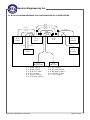
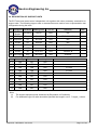
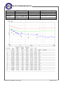
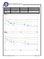
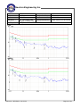
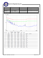
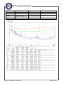
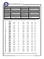
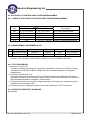
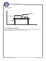
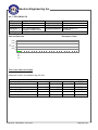
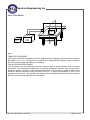
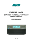
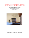
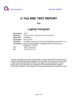
1
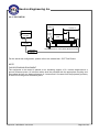
CERTIFICATE OF COMPLIANCE Ref No.: NEI-EMC-3-1311C165 Date of Issue: Nov. 27, 2013 This is to certify that the product listed in follows was (were) tested in the Neutron EMC Laboratory to comply with the required criteria levels of the follow-mentioned Generic Standards or Product Family Standard(s) and/or Basic Standard(s) based-on the essential conformity requirements of Medical Directive of 93/42/EEC. Equipment LCD Monitor Model Name DR-22 Brand Name AG Neovo Applicant Address Wistron Corporation 21F,No. 88, Sec. 1, Hsin Tai 5th Rd., Hsichih, NewTaipei city 22181,Taiwan Standard(s) EN 60601-1-2: 2007+AC:2010 CISPR 11: 2009+A1:2010 EN 61000-3-2:2006+A1:2009+A2:2009 Class D EN 61000-3-3:2008 The test data, data evaluation, and equipment configuration contained in our test report (Ref No. NEI-EMC-3-1311C165) were obtained utilizing the test procedures, test instruments, test sites that has been accredited by the Authority of TUV Rheinland and TAF according to the ISO-17025 quality assessment standard and technical standard(s). The test data contained in the referenced test report relate only to the EUT sample and item(s) tested. Steven Lu Authorized Signatory Neutron Engineering Inc. No.3,Jinshagang 1st Road, ShiXia, Dalang Town, Dong Guan, China.523792 TEL:+86-769-8318-3000 FAX:+86-769-8319-6000 Neutron Engineering Inc. EMC Test Report Issued Date Project No. Equipment Model Name Applicant Address : : : : : : Nov. 27, 2013 1311C165 LCD Monitor DR-22 Wistron Corporation 21F,No. 88, Sec. 1, Hsin Tai 5th Rd., Hsichih, NewTaipei city 22181,Taiwan Tested by: Neutron Engineering Inc. EMC Laboratory Date of Receipt: Nov. 19, 2013 Date of Test: Nov. 19, 2013 ~ Nov. 26, 2013 Te s t i n g E n g i n e e r : (Lucky Mao) Technical Manager : (James Chiu) Authorized Signatory : (Steven Lu) NEUTRON ENGINEERING INC. No.3,Jinshagang 1st Road, ShiXia, Dalang Town, Dong Guan, China.523792 TEL : +86-769-8318-3000 FAX : +86-769-8319-6000 Report No.: NEI-EMC-3-1311C165 Page 1 of 92 Neutron Engineering Inc. Declaration Neutron represents to the client that testing is done in accordance with standard procedures as applicable and that test instruments used has been calibrated with the standards traceable to National Measurement Laboratory (NML) of R.O.C., or National Institute of Standards and Technology (NIST) of U.S.A. Neutron's reports apply only to the specific samples tested under conditions. It is manufacture’s responsibility to ensure that additional production units of this model are manufactured with the identical electrical and mechanical components. Neutron shall have no liability for any declarations, inferences or generalizations drawn by the client or others from Neutron issued reports. Neutron’s reports must not be used by the client to claim product endorsement by the authorities or any agency of the Government. This report is the confidential property of the client. As a mutual protection to the clients, the public and Neutron-self, extracts from the test report shall not be reproduced except in full with Neutron’s authorized written approval. Neutron’s laboratory quality assurance procedures are in compliance with the ISO Guide 17025 requirements, and accredited by the conformity assessment authorities listed in this test report. Limitation For the use of the authority's logo is limited unless the Test Standard(s)/Scope(s)/Item(s) mentioned in this test report is (are) included in the conformity assessment authorities acceptance respective. Report No.: NEI-EMC-3-1311C165 Page 2 of 92 Neutron Engineering Inc. Table of Contents Page REPORT ISSUED HISTORY 6 1 . CERTIFICATION 7 2 . SUMMARY OF TEST RESULTS 8 2.1 TEST FACILITY 9 2.2 MEASUREMENT UNCERTAINTY 9 3 . GENERAL INFORMATION 10 3.1 GENERAL DESCRIPTION OF EUT 10 3.2 DESCRIPTION OF TEST MODES 11 3.3 BLOCK DIAGRAM SHOWING THE CONFIGURATION OF SYSTEM TESTED 13 3.4 DESCRIPTION OF SUPPORT UNITS 4 . EMC EMISSION TEST 14 15 4.1 CONDUCTED EMISSION MEASUREMENT 4.1.1 POWER LINE CONDUCTED EMISSION 4.1.2 MEASUREMENT INSTRUMENTS LIST 4.1.3 TEST PROCEDURE 4.1.4 DEVIATION FROM TEST STANDARD 4.1.5 TEST SETUP 4.1.6 EUT OPERATING CONDITIONS 4.1.7 TEST RESULTS 15 15 15 16 16 16 16 17 4.2 RADIATED EMISSION MEASUREMENT 4.2.1 LIMITS OF RADIATED EMISSION MEASUREMENT 4.2.2 MEASUREMENT INSTRUMENTS LIST 4.2.3 TEST PROCEDURE 4.2.4 DEVIATION FROM TEST STANDARD 4.2.5 TEST SETUP (Below 1000MHz) 4.3.6 TEST SETUP (ABOVE 1000MHz) 4.3.7 EUT OPERATING CONDITIONS 4.3.8 TEST RESULTS-BETWEEN 30MHZ AND 1000MHZ 4.3.9 TEST RESULTS-ABOVE 1000MHZ 28 28 29 29 29 30 30 30 31 42 4.3 HARMONICS CURRENT MEASUREMENT 4.3.1 LIMITS OF HARMONICS CURRENT MEASUREMENT 4.3.2 MEASUREMENT INSTRUMENTS LIST 4.3.3 TEST PROCEDURE 4.3.4 DEVIATION FROM TEST STANDARD 4.3.5 TEST SETUP 4.3.6 EUT OPERATING CONDITIONS 4.3.7 TEST RESULTS 49 49 49 50 50 50 50 51 4.4 VOLTAGE FLUCTUATION AND FLICKERS MEASUREMENT 54 Report No.: NEI-EMC-3-1311C165 Page 3 of 92 Neutron Engineering Inc. Table of Contents Page 4.4.1 LIMITS OF VOLTAGE FLUCTUATION AND FLICKERS MEASUREMENT 54 4.4.2 MEASUREMENT INSTRUMENTS LIST 54 4.4.3 TEST PROCEDURE 54 4.4.4 DEVIATION FROM TEST STANDARD 54 4.4.5 TESTSETUP 55 4.4.6 EUT OPERATING CONDITIONS 55 4.4.7 TEST RESULTS 56 5 . EMC IMMUNITY TEST 57 5.1 STANDARD COMPLIANCE/SERVRITY LEVEL/CRITERIA 57 5.2 DESCRIPTION OF TEST MODE 58 5.3 GENERAL PERFORMANCE CRITERIA 59 5.4 GENERAL PERFORMANCE CRITERIA TEST SETUP 59 5.5 ESD TESTING 5.5.1 TEST SPECIFICATION 5.5.2 MEASUREMENT INSTRUMENTS 5.5.3 TEST PROCEDURE 5.5.4 DEVIATION FROM TEST STANDARD 5.5.5 TEST SETUP 5.5.6 TEST RESULTS 5.5.7 PHOTO(S) SHOWN THE LOCATION(S) OF ESD EVALUATED 60 60 60 60 61 61 62 64 5.6 RS TESTING 5.6.1 TEST SPECIFICATION 5.6.2 MEASUREMENT INSTRUMENTS 5.6.3 TEST PROCEDURE 5.6.4 DEVIATION FROM TEST STANDARD 5.6.5 TEST SETUP 5.6.6 TEST RESULTS 68 68 68 68 68 69 70 5.7 EFT/BURST TESTING 5.7.1 TEST SPECIFICATION 5.7.2 MEASUREMENT INSTRUMENTS 5.7.3 TEST PROCEDURE 5.7.4 DEVIATION FROM TEST STANDARD 5.7.5 TEST SETUP 5.7.6 TEST RESULTS 71 71 71 71 71 72 73 5.8 SURGE TESTING 5.8.1 TEST SPECIFICATION 5.8.2 MEASUREMENT INSTRUMENTS 5.8.3 TEST PROCEDURE 5.8.4 DEVIATION FROM TEST STANDARD 5.8.5 TEST SETUP 5.8.6 TEST RESULTS 74 74 74 74 75 75 76 Report No.: NEI-EMC-3-1311C165 Page 4 of 92 Neutron Engineering Inc. Table of Contents Page 5.9 INJECTION CURRENT TESTING 5.9.1 TEST SPECIFICATION 5.9.2 MEASUREMENT INSTRUMENTS 5.9.3 TEST PROCEDURE 5.9.4 DEVIATION FROM TEST STANDARD 5.9.5 TEST SETUP 5.9.6 TEST RESULTS 77 77 77 77 77 78 79 5.10 POWER FREQUENCY MAGNETIC FIELD TESTING 5.10.1 TEST SPECIFICATION 5.10.2 MEASUREMENT INSTRUMENTS 5.10.3 TEST PROCEDURE 5.10.4 DEVIATION FROM TEST STANDARD 5.10.5 TEST SETUP 5.10.6 TEST RESULTS 80 80 80 80 80 81 82 5.11 VOLTAGE INTERRUPTION/DIPS TESTING 5.11.1 TEST SPECIFICATION 5.11.2 MEASUREMENT INSTRUMENTS 5.11.3 TEST PROCEDURE 5.11.4 DEVIATION FROM TEST STANDARD 5.11.5 TEST SETUP 5.11.6 TEST RESULTS 83 83 83 83 83 84 85 6 . EUT TEST PHOTO Report No.: NEI-EMC-3-1311C165 86 Page 5 of 92 Neutron Engineering Inc. REPORT ISSUED HISTORY Issued No. NEI-EMC-3-1311C165 Report No.: NEI-EMC-3-1311C165 Description Original Issue. Issued Date Nov. 27, 2013 Page 6 of 92 Neutron Engineering Inc. 1. CERTIFICATION Equipment Brand Name Model Name Applicant Date of Test Test Item Standard(s) : : : : : : : LCD Monitor AG Neovo DR-22 Wistron Corporation Nov. 19, 2013 ~ Nov. 26, 2013 ENGINEERING SAMPLE EN 60601-1-2: 2007+AC:2010 CISPR 11: 2009+A1:2010 (Group 1 Class B) EN 61000-3-2:2006 +A1:2009+A2:2009 Class D EN 61000-3-3:2008 IEC 61000-4-2: 2008 IEC 61000-4-3: 2006+A1:2007+A2:2010 IEC 61000-4-4: 2012 IEC 61000-4-5: 2005 IEC 61000-4-6: 2008 IEC 61000-4-8: 2009 IEC 61000-4-11: 2004 The above equipment has been tested and found compliance with the requirement of the relative standards by Neutron Engineering Inc. EMC Laboratory. The test data, data evaluation, and equipment configuration contained in our test report (Ref No. NEI-EMC-3-1311C165) were obtained utilizing the test procedures, test instruments, test sites that has been accredited by the Authority of TAF according to the ISO-17025 quality assessment standard and technical standard(s). Report No.: NEI-EMC-3-1311C165 Page 7 of 92 Neutron Engineering Inc. 2. SUMMARY OF TEST RESULTS Test procedures according to the technical standards: Emission (EN 60601-1-2:2007+AC:2010) Standard(s) Test Item Limit Judgment Conducted Emission Class B PASS Radiated Emission Class B PASS EN 61000-3-2: 2006 +A1:2009+A2:2009 Harmonic Current Emission Class D PASS EN 61000-3-3:2008 Voltage Fluctuations & Flicker ------ PASS CISPR 11: 2009+A1:2010 (Group 1) Remark NOTE (2) Immunity (EN 60601-1-2:2007+AC:2010) IEC 61000-4-2:2008 Electrostatic Discharge PASS IEC 61000-4-3: 2006+A1:2007+A2:2010 RF electromagnetic field PASS IEC 61000-4-4: 2012 Fast transients PASS IEC 61000-4-5:2005 Surges IEC 61000-4-6:2008 Injected Current PASS IEC 61000-4-8:2009 Power Frequency Magnetic Field PASS IEC 61000-4-11:2004 Volt. Interruptions Volt. Dips PASS NOTE (2) PASS NOTE: (1) ” N/A” denotes test is not applicable in this Test Report. (2) The performance criteria for EN60601-1-2 are listed in the item 6.2.1.10. Report No.: NEI-EMC-3-1311C165 Page 8 of 92 Neutron Engineering Inc. 2.1 TEST FACILITY The test facilities used to collect the test data in this report is DG-C01/DG-CB08 at the location of No.3,Jinshagang 1st Road, ShiXia, Dalang Town,Dong Guan, China.523792 2.2 MEASUREMENT UNCERTAINTY The reported uncertainty of measurement y ± U,where expended uncertainty U is based on a standard uncertainty multiplied by a coverage factor of k=2,providing a level of confidence of approximately 95%。 The measurement instrumentation uncertainty considerations contained in CISPR 16-4-2. A. Conducted Measurement : Test Site DG-C01 Method CISPR Measurement Frequency Range 150 KHz ~ 30MHz U,(dB) 1.94 NOTE B. Radiated Measurement : Test Site DG-CB08 Method CISPR Report No.: NEI-EMC-3-1311C165 Measurement Frequency Range 30MHz ~ 1000MHz 30MHz ~ 1000MHz 1GHz~18GHz 1GHz~18GHz Ant. H/V V H V H U, (dB) NOTE 3.57 3.96 3.07 3.62 Page 9 of 92 Neutron Engineering Inc. 3. GENERAL INFORMATION 3.1 GENERAL DESCRIPTION OF EUT Equipment LCD Monitor Brand Name AG Neovo Model Name DR-22 OEM Brand/Model Name N/A Model Difference Product Description N/A More details of EUT technical specification, please refer to the User's Manual. DC Voltage supplied from AC/DC adapter. Power Source Power Rating Connecting I/O Port(s) Model / Brand: ATM065-P240 / I/P AC 100-240V 50-60Hz 1.6-0.7A O/P DC 24V 2.71A Please refer to the User's Manual Panel #1 Manufacturer M/N CHIMEI INNOLUX M215HGE Cable Type Shielded Type Ferrite Core Length(m) Note D-Sub Shielded YES 1.8 Bonded two Ferrite Cores DVI Shielded YES 1.8 Bonded two Ferrite Cores Audio Shielded YES 1.8 Bonded two Ferrite Cores Note: 1. For a more detailed features description, please refer to the manufacturer’s specifications or the User's Manual. 2. The maximum operating frequency is 148.5MHz, so that the radiation test is up to 6GHz. (For customer requirement) Report No.: NEI-EMC-3-1311C165 Page 10 of 92 Neutron Engineering Inc. 3.2 DESCRIPTION OF TEST MODES To investigate the maximum EMI emission characteristics generated from EUT, the test system was pre-scanning tested base on the consideration of following EUT operation mode or test configuration mode which possible have effect on EMI emission level. Each of these EUT operation mode(s) or test configuration mode(s) mentioned above was evaluated respectively. Reference Test Data Page Resolution Panel Input Port & Cond. Frequency 1920*1080 60Hz D-Sub CHIMEI INNOLUX N #18 #19 Rad. Below 1G V H Above 1G V H #32 #43 #44 Worst Mode #45 #46 Worst Mode #47 #48 #33 1280*1024 75Hz #20 #34 800*600 60Hz #21 #35 1920*1080 60Hz DVI L Rad. #22 #23 #36 #37 1280*1024 75Hz #24 #38 800*600 60Hz #25 #39 PIP (DVI+CVBS 1) #26 #27 #40 #41 Remark For Harmonics Test Final Test Mode Reference Test Data Page Resolution Panel Input Port & Current Voltage #52 #53 Frequency DVI CHIMEI INNOLUX 1920*1080 60Hz For Flicks Test Final Test Mode Reference Test Data Page Resolution Panel Input Port & Frequency CHIMEI INNOLUX DVI Report No.: NEI-EMC-3-1311C165 1920*1080 60Hz #56 Page 11 of 92 Neutron Engineering Inc. For EMS Test Final Test Mode Reference Test Data Page Resolution Panel Input Port & Frequency CHIMEI INNOLUX DVI 1920*1080 60Hz NOTE (1) Note: Please refer to page 58 in the test report. Report No.: NEI-EMC-3-1311C165 Page 12 of 92 Neutron Engineering Inc. 3.3 BLOCK DIAGRAM SHOWING THE CONFIGURATION OF SYSTEM TESTED C -5 C -4 C -3 C -2 C -1 C -6 C -7 E -2 DVD E -1 EUT C -1 1 C -9 C -8 E -5 PC E -7 P rin te r C -1 0 E -6 M odem E -8 DVD E -3 K e y b o a rd C -1 C -2 C -3 C -4 C -5 C -6 Report No.: NEI-EMC-3-1311C165 U S B C a b le U S B C a b le D -S u b C a b le D V I C a b le A u d io C a b le S -V id e o C a b le E -4 M ouse C -7 A V C a b le C -8 R S 2 3 2 C a b le C -9 P a ra lle l C a b le C -1 0 H D M I C a b le C -1 1 A V C a b le Page 13 of 92 Neutron Engineering Inc. 3.4 DESCRIPTION OF SUPPORT UNITS The EUT has been tested as an independent unit together with other necessary accessories or support units. The following support units or accessories were used to form a representative test configuration during the tests. Item Equipment Mfr/Brand Model/Type No. LCD E-1 AG Neovo DR-22 Monitor E-2 DVD Player Pioneer DV-400 FCC ID Series No. Note DOC N/A EUT VER GFKD000248CN E-3 keyboard hp SK-2885 DOC N/A E-4 mouse hp SM-202 DOC N/A E-5 PC Dell 745 DOC G7K832X E-6 Modem ACEEX DM-1414V IFAXDm1414 0603002131 E-7 Printer SII DPU-414 DOC 3018507 B sony BD-S490 VER 4028055 E-8 DVD Player Item Shielded Type Ferrite Core Length Note C-1 YES NO 1.8m C-2 YES YES 1.8m C-3 YES YES 1.8m 2 Cores C-4 YES YES 1.8m 2 Cores C-5 YES YES 1.8m 2 Cores C-6 YES NO 1.5m C-7 NO NO 1.5m C-8 YES NO 1.8m C-9 YES NO 1.5m C-10 YES NO 1.8m Note: (1) (2) The support equipment was authorized by Declaration of Conformity. For detachable type I/O cable should be specified the length in cm in『Length』column. Report No.: NEI-EMC-3-1311C165 Page 14 of 92 Neutron Engineering Inc. 4. EMC EMISSION TEST 4.1 CONDUCTED EMISSION MEASUREMENT 4.1.1 POWER LINE CONDUCTED EMISSION (FREQUENCY RANGE 150KHZ-30MHZ) FREQUENCY (MHz) Class A (dBuV) Class B (dBuV) Quasi-peak Average Quasi-peak Average 0.15 -0.5 79.00 66.00 66 - 56 * 56 - 46 * 0.50 -5.0 73.00 60.00 56.00 46.00 5.0 -30.0 73.00 60.00 60.00 50.00 Note: (1) The tighter limit applies at the band edges. (2) The limit of " * " marked band means the limitation decreases linearly with the logarithm of the frequency in the range. 4.1.2 MEASUREMENT INSTRUMENTS LIST Item Kind of Equipment 1 LISN Manufacturer EMCO Type No. 3816/2SH Serial No. 00052766 Calibrated until Apr. 25, 2014 2 LISN R&S ENV216 100526 Feb. 25, 2014 3 Test Cable N/A RG400 12m N/A Mar. 15, 2014 4 EMI Test Receiver R&S ESCS30 826547/022 Apr. 25, 2014 5 50Ω Terminator SHX TF2-3G-A 08122901 Apr. 25, 2014 Remark: ” N/A” denotes No Model Name , Serial No. or No Calibration specified. Report No.: NEI-EMC-3-1311C165 Page 15 of 92 Neutron Engineering Inc. 4.1.3 TEST PROCEDURE a. The EUT was placed 0.8 meters from the horizontal ground plane with EUT being connected to the power mains through a line impedance stabilization network (LISN). All other support equipments powered from additional LISN(s). The LISN provide 50 Ohm/ 50uH of coupling impedance for the measuring instrument. b. Interconnecting cables that hang closer than 40 cm to the ground plane shall be folded back and forth in the center forming a bundle 30 to 40 cm long. c. I/O cables that are not connected to a peripheral shall be bundled in the center. The end of the cable may be terminated, if required, using the correct terminating impedance. The overall length shall not exceed 1 m. d. LISN at least 80 cm from nearest part of EUT chassis. e. For the actual test configuration, please refer to the related Item –EUT Test Photos. 4.1.4 DEVIATION FROM TEST STANDARD No deviation 4.1.5 TEST SETUP 4.1.6 EUT OPERATING CONDITIONS The EUT exercise program used during radiated and/or conducted emission measurement was designed to exercise the various system components in a manner similar to a typical use. The program contained on a PC hard disk and is auto-starting on power-up. Once loaded, the program sequentially exercises each system component in turn. The sequence used is: 1. Read (write) from (to) mass storage device. 2. Send " H " pattern to video port device (Monitor). 3. Send " H " pattern to parallel port device (Printer). 4. Send " H " pattern to serial port device (Modem). 5. EUT Connected to PC via audio cable. 6. EUT connected to DVD via S-Video & AV cable. 7. Repeated from 2 to 6 continuously. As the keyboard and mouse are strictly input devices, no data is transmitted to (from) them during test. They are, however, continuously scanned for data input activity. Report No.: NEI-EMC-3-1311C165 Page 16 of 92 Neutron Engineering Inc. 4.1.7 TEST RESULTS Remark: (1) Reading in which marked as QP means measurements by using are Quasi-Peak Mode with Detector BW=9KHz; SPA setting in RBW=10KHz,VBW =10KHz, Swp. Time = 0.3 sec./MHz. Reading in which marked as AV means measurements by using are Average Mode with instrument setting in RBW=10KHz,VBW =10KHz, Swp. Time =0.3 sec./MHz. (2) All readings are QP Mode value unless otherwise stated AVG in column of『Note』 . If the QP Mode Measured value compliance with the QP Limits and lower than AVG Limits, the EUT shall be deemed to meet both QP & AVG Limits and then only QP Mode was measured, but AVG Mode didn‘t perform. In this case, a “ * ” marked in AVG Mode column of Interference Voltage Measured. (3) Measuring frequency range from 150KHz to 30MHz. Report No.: NEI-EMC-3-1311C165 Page 17 of 92 Neutron Engineering Inc. EUT: Temperature: Pressure: Test Mode : Test Engineer : LCD Monitor 23 ℃ 1010 hPa D-Sub 1920*1080 60Hz Adapter: ATM065-P240 Lucky Mao Report No.: NEI-EMC-3-1311C165 Model Name : Relative Humidity: Test Power : DR-22 50 % AC 230V/50Hz Panel(Brand/Model): CHIMEI INNOLUX/ M215HGE Phase: Line Page 18 of 92 Neutron Engineering Inc. EUT: Temperature: Pressure: Test Mode : Test Engineer : LCD Monitor 23 ℃ 1010 hPa D-Sub 1920*1080 60Hz Adapter: ATM065-P240 Lucky Mao Report No.: NEI-EMC-3-1311C165 Model Name : Relative Humidity: Test Power : DR-22 50 % AC 230V/50Hz Panel(Brand/Model): CHIMEI INNOLUX/ M215HGE Phase: Neutral Page 19 of 92 Neutron Engineering Inc. EUT: Temperature: Pressure: Test Mode : Test Engineer : Line LCD Monitor 23 ℃ 1010 hPa D-Sub 1280*1024 75Hz Adapter: ATM065-P240 Lucky Mao Model Name : Relative Humidity: Test Power : DR-22 50 % AC 230V/50Hz Panel(Brand/Model): CHIMEI INNOLUX/ M215HGE Neutral Report No.: NEI-EMC-3-1311C165 Page 20 of 92 Neutron Engineering Inc. EUT: Temperature: Pressure: Test Mode : Test Engineer : Line LCD Monitor 23 ℃ 1010 hPa D-Sub 800*600 60Hz Adapter: ATM065-P240 Lucky Mao Model Name : Relative Humidity: Test Power : DR-22 50 % AC 230V/50Hz Panel(Brand/Model): CHIMEI INNOLUX/ M215HGE Neutral Report No.: NEI-EMC-3-1311C165 Page 21 of 92 Neutron Engineering Inc. EUT: Temperature: Pressure: Test Mode : Test Engineer : LCD Monitor 23 ℃ 1010 hPa DVI 1920*1080 60Hz Adapter: ATM065-P240 Lucky Mao Report No.: NEI-EMC-3-1311C165 Model Name : Relative Humidity: Test Power : DR-22 50 % AC 230V/50Hz Panel(Brand/Model): CHIMEI INNOLUX/ M215HGE Phase: Line Page 22 of 92 Neutron Engineering Inc. EUT: Temperature: Pressure: Test Mode : Test Engineer : LCD Monitor 23 ℃ 1010 hPa DVI 1920*1080 60Hz Adapter: ATM065-P240 Lucky Mao Report No.: NEI-EMC-3-1311C165 Model Name : Relative Humidity: Test Power : DR-22 50 % AC 230V/50Hz Panel(Brand/Model): CHIMEI INNOLUX/ M215HGE Phase: Neutral Page 23 of 92 Neutron Engineering Inc. EUT: Temperature: Pressure: Test Mode : Test Engineer : Line LCD Monitor 23 ℃ 1010 hPa DVI 1280*1024 75Hz Adapter: ATM065-P240 Lucky Mao Model Name : Relative Humidity: Test Power : DR-22 50 % AC 230V/50Hz Panel(Brand/Model): CHIMEI INNOLUX/ M215HGE Neutral Report No.: NEI-EMC-3-1311C165 Page 24 of 92 Neutron Engineering Inc. EUT: Temperature: Pressure: Test Mode : Test Engineer : Line LCD Monitor 23 ℃ 1010 hPa DVI 800*600 60Hz Adapter: ATM065-P240 Lucky Mao Model Name : Relative Humidity: Test Power : DR-22 50 % AC 230V/50Hz Panel(Brand/Model): CHIMEI INNOLUX/ M215HGE Neutral Report No.: NEI-EMC-3-1311C165 Page 25 of 92 Neutron Engineering Inc. EUT: Temperature: Pressure: Test Mode : Test Engineer : LCD Monitor 23 ℃ 1010 hPa PIP (DVI+CVBS 1) Adapter: ATM065-P240 Lucky Mao Report No.: NEI-EMC-3-1311C165 Model Name : Relative Humidity: Test Power : DR-22 50 % AC 230V/50Hz Panel(Brand/Model): CHIMEI INNOLUX/ M215HGE Phase: Line Page 26 of 92 Neutron Engineering Inc. EUT: Temperature: Pressure: Test Mode : Test Engineer : LCD Monitor 23 ℃ 1010 hPa PIP (DVI+CVBS 1) Adapter: ATM065-P240 Lucky Mao Report No.: NEI-EMC-3-1311C165 Model Name : Relative Humidity: Test Power : DR-22 50 % AC 230V/50Hz Panel(Brand/Model): CHIMEI INNOLUX/ M215HGE Phase: Neutral Page 27 of 92 Neutron Engineering Inc. 4.2 RADIATED EMISSION MEASUREMENT 4.2.1 LIMITS OF RADIATED EMISSION MEASUREMENT (BELOW 1000MHZ) FREQUENCY (MHz) Class A (at 10m) Class B (at 10m) dBuV/m dBuV/m 40 30 30 – 230 230 – 1000 47 37 Notes: (1) The limit for radiated test was performed according to as following: CISPR 22/ FCC PART 15B /ICES-003. (2) The tighter limit applies at the band edges. (3) Emission level (dBuV/m)=20log Emission level (uV/m). LIMITS OF RADIATED EMISSION MEASUREMENT (ABOVE 1000MHZ) FREQUENCY (MHz) Class A (dBuV/m) (at 3m) Class B (dBuV/m) (at 3m) PEAK AVERAGE PEAK AVERAGE 1000-3000 76 56 70 50 3000-6000 80 60 74 54 Notes: (1) The lower limit applies at the transition frequency. FREQUENCY RANGE OF RADIATED MEASUREMENT (FOR UNINTENTIONAL RADIATORS) Highest frequency generated or Upper frequency of measurement used in the device or on which the device operates or tunes (MHz) Range (MHz) Below 108 1000 108 – 500 2000 500 – 1000 5000 5 harmonic of the highest frequency or 6 GHz, whichever is lower Above 1000 Report No.: NEI-EMC-3-1311C165 th Page 28 of 92 Neutron Engineering Inc. 4.2.2 MEASUREMENT INSTRUMENTS LIST Item Kind of Equipment 1 Antenna Manufacturer EMCO Type No. 3142C Serial No. 00066462 Calibrated until Apr. 25, 2014 2 Antenna EMCO 3142C 00066464 Apr. 25, 2014 3 Amplifier Agilent 8447D 2944A11203 Nov. 09, 2014 4 Amplifier Agilent 8447D 2944A11204 Nov. 09, 2014 5 Spectrum Analyzer Agilent E4443A MY48250370 Nov. 09, 2014 6 RF Pre-selector Agilent Nov. 09, 2014 7 Test Cable N/A 8 Test Cable N/A 9 Spectrum Analyzer Agilent N9039A MY46520201 Cable_5m_8 N/A m_15m Cable_5m_1 N/A 1m_15m E4447A MY48250208 10 Agilent N9039A MY46520214 Nov. 09, 2014 ETS-Lindgren 2090 N/A N/A 12 RF Pre-selector Multi-Device Controller Horn Antenna EMCO 3115 9605-4803 Apr. 25, 2014 13 Amplifier Agilent 8449B 3008A02584 Nov. 09, 2014 14 Spectrum Analyzer Agilent Nov. 09, 2014 15 Test Cable Huber+Suhner E4447A MY48250208 SUCOFLEX_ N/A 15m_4m 11 Jan. 15, 2014 Jan. 15, 2014 Nov. 09, 2014 Jan. 15, 2014 Remark: ” N/A” denotes No Model Name / Serial No. and No Calibration specified. 4.2.3 TEST PROCEDURE a. The measuring distance of at 10 m shall be used for measurements at frequency up to 1GHz. For frequencies above 1GHz, any suitable measuring distance may be used. b. The EUT was placed on the top of a rotating table 0.8 meters above the ground at a 10 meter semi-anechoic chamber. The table was rotated 360 degrees to determine the position of the highest radiation. c. The height of the equipment or of the substitution antenna shall be 0.8 m; the height of the test antenna shall vary between 1 m to 4 m. Both horizontal and vertical polarizations of the antenna are set to make the measurement. d. The initial step in collecting radiated emission data is a spectrum analyzer peak detector mode pre-scanning the measurement frequency range. Significant peaks are then marked and then Quasi Peak detector mode re-measured. e. If the Peak Mode measured value compliance with and lower than Quasi Peak Mode Limit, the EUT shall be deemed to meet QP Limits and then no additional QP Mode measurement performed. f. For the actual test configuration, please refer to the related Item –EUT Test Photos. 4.2.4 DEVIATION FROM TEST STANDARD No deviation Report No.: NEI-EMC-3-1311C165 Page 29 of 92 Neutron Engineering Inc. 4.2.5 TEST SETUP (Below 1000MHz) 4.3.6 TEST SETUP (ABOVE 1000MHz) 4.3.7 EUT OPERATING CONDITIONS The EUT tested system was configured as the statements of 4.1.6 Unless otherwise a special operating condition is specified in the follows during the testing. Report No.: NEI-EMC-3-1311C165 Page 30 of 92 Neutron Engineering Inc. 4.3.8 TEST RESULTS-BETWEEN 30MHZ AND 1000MHZ Remark : (1) Reading in which marked as QP or Peak means measurements by using are Quasi-Peak Mode or Peak Mode with Detector BW=120KHz; SPA setting in RBW=120KHz, VBW =120KHz, Swp. Time = 0.3 sec./MHz. (2) All readings are Peak unless otherwise stated QP in column of『Note』. Peak denotes that the Peak reading compliance with the QP Limits and then QP Mode measurement didn‘t perform. (3) Measuring frequency range from 30MHz to 1000MHz. (4) If the peak scan value lower limit more than 20dB, then this signal data does not show in table. Report No.: NEI-EMC-3-1311C165 Page 31 of 92 Neutron Engineering Inc. EUT: Temperature: Pressure: Test Mode : Test Engineer : LCD Monitor 23 ℃ 1010 hPa D-Sub 1920*1080 60Hz Adapter: ATM065-P240 Lucky Mao Report No.: NEI-EMC-3-1311C165 Model Name : Relative Humidity: Test Power : DR-22 50 % AC 230V/50Hz Panel(Brand/Model): CHIMEI INNOLUX / M215HGE Polarization: Vertical Page 32 of 92 Neutron Engineering Inc. EUT: Temperature: Pressure: Test Mode : Test Engineer : LCD Monitor 23 ℃ 1010 hPa D-Sub 1920*1080 60Hz Adapter: ATM065-P240 Lucky Mao Report No.: NEI-EMC-3-1311C165 Model Name : Relative Humidity: Test Power : DR-22 50 % AC 230V/50Hz Panel(Brand/Model): CHIMEI INNOLUX / M215HGE Polarization: Horizontal Page 33 of 92 Neutron Engineering Inc. EUT: Temperature: Pressure: Test Mode : Test Engineer : LCD Monitor 23 ℃ 1010 hPa D-Sub 1280*1024 75Hz Adapter: ATM065-P240 Lucky Mao Model Name : Relative Humidity: Test Power : DR-22 50 % AC 230V/50Hz Panel(Brand/Model): CHIMEI INNOLUX / M215HGE Vertical Horizontal Report No.: NEI-EMC-3-1311C165 Page 34 of 92 Neutron Engineering Inc. EUT: Temperature: Pressure: Test Mode : Test Engineer : LCD Monitor 23 ℃ 1010 hPa D-Sub 800*600 60Hz Adapter: ATM065-P240 Lucky Mao Model Name : Relative Humidity: Test Power : DR-22 50 % AC 230V/50Hz Panel(Brand/Model): CHIMEI INNOLUX / M215HGE Vertical Horizontal Report No.: NEI-EMC-3-1311C165 Page 35 of 92 Neutron Engineering Inc. EUT: Temperature: Pressure: Test Mode : Test Engineer : LCD Monitor 23 ℃ 1010 hPa DVI 1920*1080 60Hz Adapter: ATM065-P240 Lucky Mao Report No.: NEI-EMC-3-1311C165 Model Name : Relative Humidity: Test Power : DR-22 50 % AC 230V/50Hz Panel(Brand/Model): CHIMEI INNOLUX / M215HGE Polarization: Vertical Page 36 of 92 Neutron Engineering Inc. EUT: Temperature: Pressure: Test Mode : Test Engineer : LCD Monitor 23 ℃ 1010 hPa DVI 1920*1080 60Hz Adapter: ATM065-P240 Lucky Mao Report No.: NEI-EMC-3-1311C165 Model Name : Relative Humidity: Test Power : DR-22 50 % AC 230V/50Hz Panel(Brand/Model): CHIMEI INNOLUX / M215HGE Polarization: Horizontal Page 37 of 92 Neutron Engineering Inc. EUT: Temperature: Pressure: Test Mode : Test Engineer : LCD Monitor 23 ℃ 1010 hPa DVI 1280*1024 75Hz Adapter: ATM065-P240 Lucky Mao Model Name : Relative Humidity: Test Power : DR-22 50 % AC 230V/50Hz Panel(Brand/Model): CHIMEI INNOLUX / M215HGE Vertical Horizontal Report No.: NEI-EMC-3-1311C165 Page 38 of 92 Neutron Engineering Inc. EUT: Temperature: Pressure: Test Mode : Test Engineer : LCD Monitor 23 ℃ 1010 hPa DVI 800*600 60Hz Adapter: ATM065-P240 Lucky Mao Model Name : Relative Humidity: Test Power : DR-22 50 % AC 230V/50Hz Panel(Brand/Model): CHIMEI INNOLUX / M215HGE Vertical Horizontal Report No.: NEI-EMC-3-1311C165 Page 39 of 92 Neutron Engineering Inc. EUT: Temperature: Pressure: Test Mode : Test Engineer : LCD Monitor 23 ℃ 1010 hPa PIP (DVI+CVBS 1) Adapter: ATM065-P240 Lucky Mao Report No.: NEI-EMC-3-1311C165 Model Name : Relative Humidity: Test Power : DR-22 50 % AC 230V/50Hz Panel(Brand/Model): CHIMEI INNOLUX / M215HGE Polarization: Vertical Page 40 of 92 Neutron Engineering Inc. EUT: Temperature: Pressure: Test Mode : Test Engineer : LCD Monitor 23 ℃ 1010 hPa PIP (DVI+CVBS 1) Adapter: ATM065-P240 Lucky Mao Report No.: NEI-EMC-3-1311C165 Model Name : Relative Humidity: Test Power : DR-22 50 % AC 230V/50Hz Panel(Brand/Model): CHIMEI INNOLUX / M215HGE Polarization: Horizontal Page 41 of 92 Neutron Engineering Inc. 4.3.9 TEST RESULTS-ABOVE 1000MHZ Remark : (1) Reading in which marked as Peak or AVG means measurements by using are Peak Mode or AVG with Detector BW=1MHz; SPA setting in RBW=1MHz, VBW =1MHz, Swp. Time = 0.3 sec./MHz, AVG Mode with detector BW=1MHz; SPA setting in RBW=1MHz, VBW =10Hz, Swp. Time = 0.3 sec./MHz. (2) All readings are Peak unless otherwise stated QP in column of『Note』. Peak denotes that the Peak reading Compliance with the QP Limits and then QP Mode measurement didn‘t perform. (3) Measuring frequency range from 1GHz to 6GHz. (4) For testing above 1GHz, the emissions level of the EUT in peak mode was lower than average limit (that means the emissions level in peak mode also Complies with the limit in average mode), then testing will be stopped and peak values of EUT will be reported, otherwise, the emissions will be measured in average mode again and reported. Report No.: NEI-EMC-3-1311C165 Page 42 of 92 Neutron Engineering Inc. EUT: Temperature: Pressure: Test Mode : Test Engineer : LCD Monitor 23 ℃ 1010 hPa D-Sub 1920*1080 60Hz Adapter: ATM065-P240 Lucky Mao Report No.: NEI-EMC-3-1311C165 Model Name : Relative Humidity: Test Power : DR-22 50 % AC 230V/50Hz Panel(Brand/Model): CHIMEI INNOLUX / M215HGE Polarization: Vertical Page 43 of 92 Neutron Engineering Inc. EUT: Temperature: Pressure: Test Mode : Test Engineer : LCD Monitor 23 ℃ 1010 hPa D-Sub 1920*1080 60Hz Adapter: ATM065-P240 Lucky Mao Report No.: NEI-EMC-3-1311C165 Model Name : Relative Humidity: Test Power : DR-22 50 % AC 230V/50Hz Panel(Brand/Model): CHIMEI INNOLUX / M215HGE Polarization: Horizontal Page 44 of 92 Neutron Engineering Inc. EUT: Temperature: Pressure: Test Mode : Test Engineer : LCD Monitor 23 ℃ 1010 hPa DVI 1920*1080 60Hz Adapter: ATM065-P240 Lucky Mao Report No.: NEI-EMC-3-1311C165 Model Name : Relative Humidity: Test Power : DR-22 50 % AC 230V/50Hz Panel(Brand/Model): CHIMEI INNOLUX / M215HGE Polarization: Vertical Page 45 of 92 Neutron Engineering Inc. EUT: Temperature: Pressure: Test Mode : Test Engineer : LCD Monitor 23 ℃ 1010 hPa DVI 1920*1080 60Hz Adapter: ATM065-P240 Lucky Mao Report No.: NEI-EMC-3-1311C165 Model Name : Relative Humidity: Test Power : DR-22 50 % AC 230V/50Hz Panel(Brand/Model): CHIMEI INNOLUX / M215HGE Polarization: Horizontal Page 46 of 92 Neutron Engineering Inc. EUT: Temperature: Pressure: Test Mode : Test Engineer : LCD Monitor 23 ℃ 1010 hPa PIP (DVI+CVBS 1) Adapter: ATM065-P240 Lucky Mao Report No.: NEI-EMC-3-1311C165 Model Name : Relative Humidity: Test Power : DR-22 50 % AC 230V/50Hz Panel(Brand/Model): CHIMEI INNOLUX / M215HGE Polarization: Vertical Page 47 of 92 Neutron Engineering Inc. EUT: Temperature: Pressure: Test Mode : Test Engineer : LCD Monitor 23 ℃ 1010 hPa PIP (DVI+CVBS 1) Adapter: ATM065-P240 Lucky Mao Report No.: NEI-EMC-3-1311C165 Model Name : Relative Humidity: Test Power : DR-22 50 % AC 230V/50Hz Panel(Brand/Model): CHIMEI INNOLUX / M215HGE Polarization: Horizontal Page 48 of 92 Neutron Engineering Inc. 4.3 HARMONICS CURRENT MEASUREMENT 4.3.1 LIMITS OF HARMONICS CURRENT MEASUREMENT IEC 555-2 Table - I Equipment Harmonic Category Order Table - II Max. Permissible Equipment Harmonic Max. Permissible Harmonic Current Harmonic Current n Non Portable Tools or TV Receivers (in Ampers) Odd Harmonics 3 2.30 5 1.14 7 0.77 9 0.40 11 0.33 13 0.21 0.15.15/n 15n39 Even Harmonics 2 1.08 4 0.43 6 0.30 0.23.8/n 8n40 Category Order n TV Receivers (in Ampers) Odd Harmonics 3 0.80 5 0.60 7 0.45 9 0.30 11 0.17 13 0.12 0.10.15/n 15n39 Even Harmonics 2 0.30 4 0.15 DC 0.05 EN 61000-3-2/IEC 61000-3-2 Equipment Max. Permissible Equipment Harmonic Max. Permissible Category Harmonic Current Category Order Harmonic Current (in Ampers) Class A Same as Limits Specified in 4-2.1, Table - I, but only odd harmonics required Class D n (in A) (mA/w) 3 2.30 3.4 5 1.14 1.9 7 0.77 1.0 9 0.40 0.5 11 0.33 0.35 see Table I 3.85/n 13n39 only odd harmonics required 4.3.2 MEASUREMENT INSTRUMENTS LIST Item Kind of Equipment 1 Harmonic & Flicker 2 Power Source Manufacturer California Type No. PACS-1 Serial No. 72344 Calibrated until Aug. 24, 2014 California 3001iX 56309 Aug. 24, 2014 Remark: ” N/A” denotes No Model Name / Serial No. and No Calibration specified. Report No.: NEI-EMC-3-1311C165 Page 49 of 92 Neutron Engineering Inc. 4.3.3 TEST PROCEDURE a. The EUT was placed on the top of a wooden table 0.8 meters above the ground and operated to produce the maximum harmonic components under normal operating conditions. b. The classification of EUT is according to section 5 of EN 61000-3-2:2006 +A1:2009+ A2:2009. The EUT is classified as follows: Class A: Balanced three-phase equipment, Household appliances excluding equipment as Class D, Tools excluding portable tools, Dimmers for incandescent lamps, audio equipment, equipment not specified in one of the three other classes. Class B: Portable tools. Portable tools.; Arc welding equipment which is not professional equipment. Class C: Lighting equipment. Class D: Equipment having a specified power less than or equal to600 W of the following types: Personal computers and personal computer monitors and television receivers. c. The correspondent test program of test instrument to measure the current harmonics emanated from EUT is chosen. The measure time shall be not less than the time necessary for the EUT to be exercised. d. For the actual test configuration, please refer to the related item –EUT Test Photos. 4.3.4 DEVIATION FROM TEST STANDARD No deviation 4.3.5 TEST SETUP Voltage Supply To EUT To AC Mains Power Supply Power Analyzer & Power Source EUT Non-Metallic Table 4.3.6 EUT OPERATING CONDITIONS The EUT tested system was configured as the statements of 4.1.6 Unless otherwise a special operating condition is specified in the follows during the testing. Report No.: NEI-EMC-3-1311C165 Page 50 of 92 Neutron Engineering Inc. 4.3.7 TEST RESULTS Harmonics – Class-D per Ed. 3.2(Run time) EUT: Temperature: Pressure: Test Mode : Test Engineer : LCD Monitor 23 ℃ 1007 hPa DVI 1920*1080 60Hz Adapter: ATM065-P240 Lucky Mao Model Name : Relative Humidity: Test Power : DR-22 60 % AC 230V/50Hz CHIMEI INNOLUX / Panel(Brand/Model): M215HGE 1.5 300 1.0 200 0.5 100 0.0 0 -0.5 -100 -1.0 -200 -1.5 -300 Current RMS(Amps) Harmonics and Class D limit line Voltage (Volts) Current (Amps) Current & voltage waveforms European Limits 0.10 0.09 0.08 0.07 0.06 0.05 0.04 0.03 0.02 0.01 0.00 4 Test result: Pass 8 12 16 20 24 Harmonic # 28 32 36 40 Worst harmonic was #0 with 0.00 of the limit. Report No.: NEI-EMC-3-1311C165 Page 51 of 92 Neutron Engineering Inc. Current Test Result Summary (Run time) EUT: LCD Monitor Temperature: 23 ℃ Pressure: 1007 hPa Highest parameter values during test: V_RMS (Volts): 229.94 I_Peak (Amps): 1.391 I_Fund (Amps): 0.088 Power (Watts): 19.3 DVI 1920*1080 60Hz Test Mode : Adapter: ATM065-P240 Test Engineer : Lucky Mao Model Name : DR-22 Relative Humidity: 60 % Test Power : AC 230V/50Hz Frequency(Hz): I_RMS (Amps): Crest Factor: Power Factor: 50.00 0.246 5.688 0.344 CHIMEI INNOLUX / Panel(Brand/Model): M215HGE Harm#Harms(avg)100%Limit%of Limit Harms(max) 150%Limit %of Limit Status 2 3 4 5 6 7 8 9 10 11 12 13 14 15 16 17 18 19 20 21 22 23 24 25 26 27 28 29 30 31 32 33 34 35 36 37 38 39 40 0.002 0.082 0.002 0.080 0.002 0.078 0.002 0.074 0.002 0.071 0.002 0.066 0.002 0.062 0.002 0.057 0.002 0.051 0.002 0.046 0.002 0.041 0.001 0.035 0.001 0.030 0.001 0.025 0.001 0.020 0.001 0.016 0.001 0.012 0.001 0.009 0.001 0.006 0.000 0.066 0.0 0.083 0.098 0.00 N/L 0.037 0.0 0.080 0.055 0.00 N/L 0.019 0.0 0.078 0.029 0.00 N/L 0.010 0.0 0.075 0.014 0.00 N/L 0.007 0.0 0.071 0.010 0.00 N/L 0.006 0.0 0.067 0.009 0.00 N/L 0.005 0.0 0.062 0.007 0.00 N/L 0.004 0.0 0.057 0.007 0.00 N/L 0.004 0.0 0.052 0.006 0.00 N/L 0.004 0.0 0.046 0.005 0.00 N/L 0.003 0.0 0.041 0.005 0.00 N/L 0.003 0.0 0.035 0.004 0.00 N/L 0.003 0.0 0.030 0.004 0.00 N/L 0.003 0.0 0.025 0.004 0.00 N/L 0.002 0.0 0.021 0.004 0.00 N/L 0.002 0.0 0.016 0.003 0.00 N/L 0.002 0.0 0.012 0.003 0.00 N/L 0.002 0.0 0.009 0.003 0.00 N/L 0.002 0.0 0.006 0.003 0.00 N/L Note: The EUT power level is below 75.0 Watts and therefore has no defined limits Report No.: NEI-EMC-3-1311C165 Page 52 of 92 Neutron Engineering Inc. Voltage Source Verification Data (Run time) EUT: LCD Monitor Temperature: 23 ℃ Pressure: 1007 hPa Highest parameter values during test: V_RMS (Volts): 229.94 I_Peak (Amps): 1.391 I_Fund (Amps): 0.088 Power (Watts): 19.3 DVI 1920*1080 60Hz Test Mode : Adapter: ATM065-P240 Test Engineer : Lucky Mao Harm# 2 3 4 5 6 7 8 9 10 11 12 13 14 15 16 17 18 19 20 21 22 23 24 25 26 27 28 29 30 31 32 33 34 35 36 37 38 39 40 Model Name : Relative Humidity: Test Power : DR-22 60 % AC 230V/50Hz Frequency(Hz): I_RMS (Amps): Crest Factor: Power Factor: 50.00 0.246 5.688 0.344 CHIMEI INNOLUX / Panel(Brand/Model): M215HGE Harmonics V-rms Limit V-rms % of Limit Status 0.129 0.534 0.060 0.039 0.027 0.060 0.017 0.016 0.023 0.054 0.016 0.049 0.007 0.048 0.012 0.043 0.013 0.049 0.016 0.046 0.014 0.046 0.007 0.040 0.011 0.039 0.008 0.030 0.007 0.030 0.006 0.025 0.003 0.021 0.003 0.014 0.005 0.012 0.007 0.460 2.069 0.460 0.920 0.460 0.690 0.460 0.460 0.460 0.230 0.230 0.230 0.230 0.230 0.230 0.230 0.230 0.230 0.230 0.230 0.230 0.230 0.230 0.230 0.230 0.230 0.230 0.230 0.230 0.230 0.230 0.230 0.230 0.230 0.230 0.230 0.230 0.230 0.230 27.95 25.79 13.12 4.27 5.95 8.72 3.75 3.38 5.00 23.34 6.75 21.49 3.23 20.98 5.17 18.78 5.72 21.16 7.05 19.83 6.06 19.85 3.13 17.59 4.91 16.79 3.37 13.03 3.04 12.91 2.47 10.66 1.51 9.22 1.49 6.15 2.08 5.43 3.05 OK OK OK OK OK OK OK OK OK OK OK OK OK OK OK OK OK OK OK OK OK OK OK OK OK OK OK OK OK OK OK OK OK OK OK OK OK OK OK Report No.: NEI-EMC-3-1311C165 Page 53 of 92 Neutron Engineering Inc. 4.4 VOLTAGE FLUCTUATION AND FLICKERS MEASUREMENT 4.4.1 LIMITS OF VOLTAGE FLUCTUATION AND FLICKERS MEASUREMENT Tests Pst Plt dc dmax d (t) Limits IEC555-3 IEC/EN 61000-3-3 1.0, Tp= 10 min. 1.0, Tp= 10 min. N/A 0.65, Tp=2 hr. 3% 3.3% 4% 4% N/A 3.3% for 500 ms Descriptions Short Term Flicker Indicator Long Term Flicker Indicator Relative Steady-State V-Chang Maximum Relative V-change Relative V-change characteristic 4.4.2 MEASUREMENT INSTRUMENTS LIST Item Kind of Equipment 1 Harmonic & Flicker 2 Power Source Manufacturer California Type No. PACS-1 Serial No. 72344 Calibrated until Aug. 24, 2014 California 3001iX 56309 Aug. 24, 2014 Remark: ” N/A” denotes No Model Name / Serial No. and No Calibration specified. 4.4.3 TEST PROCEDURE a. Harmonic Current Test: Test was performed according to the procedures specified in Clause 5.0 of IEC555-2 and/or Sub-clause 6.2 of IEC/EN 61000-3-2 depend on which standard adopted for compliance measurement. b. Fluctuation and Flickers Test: Tests was performed according to the Test Conditions/Assessment of Voltage Fluctuations specified in Clause 5.0/6.0 of IEC555-3 and/or Clause 6.0/4.0 of IEC/EN 61000-3-3 depend on which standard adopted for compliance measurement. c. All types of harmonic current and/or voltage fluctuation in this report are assessed by direct measurement using flicker-meter. d. For the actual test configuration, please refer to the related Item –EUT Test Photos. 4.4.4 DEVIATION FROM TEST STANDARD No deviation Report No.: NEI-EMC-3-1311C165 Page 54 of 92 Neutron Engineering Inc. 4.4.5 TESTSETUP Voltage Supply To EUT To AC Mains Power Supply Power Analyzer & Power Source EUT Non-Metallic Table 4.4.6 EUT OPERATING CONDITIONS The EUT tested system was configured as the statements of 4.1.6 Unless otherwise a special operating condition is specified in the follows during the testing. Report No.: NEI-EMC-3-1311C165 Page 55 of 92 Neutron Engineering Inc. 4.4.7 TEST RESULTS EUT: Temperature: Pressure: LCD Monitor 23 ℃ 1007 hPa DVI 1920*1080 60Hz Test Mode : Adapter: ATM065-P240 Test Engineer : Lucky Mao Model Name : Relative Humidity: Test Power : DR-22 60 % AC 230V/50Hz CHIMEI INNOLUX / Panel(Brand/Model): M215HGE Psti and limit line European Limits 1.00 Pst 0.75 0.50 0.25 19:40:10 Time is too short for Plt plot Parameter values recorded during the test: Vrms at the end of test (Volt): 229.90 Highest dt (%): Time(mS) > dt: Highest dc (%): Highest dmax (%): Highest Pst (10 min. period): Highest Plt (2 hr. period): Report No.: NEI-EMC-3-1311C165 0.00 Test limit (%): 0.0 Test limit (mS): 0.00 Test limit (%): 0.00 Test limit (%): 0.064 Test limit: 0.028 Test limit: 3.30 500.0 3.30 4.00 1.000 0.650 PASS PASS PASS PASS PASS PASS Page 56 of 92 Neutron Engineering Inc. 5. EMC IMMUNITY TEST 5.1 STANDARD COMPLIANCE/SERVRITY LEVEL/CRITERIA Tests Standard No. 1. ESD IEC/EN 61000-4-2 2. RS IEC/EN 61000-4-3 3. EFT/Burst IEC/EN 61000-4-4 4. Surges IEC/EN 61000-4-5 5 Injected Current IEC/EN 61000-4-6 TEST SPECIFICATION Level 8kV air discharge 6kV contact discharge 6kV HCP discharge 6kV VCP discharge 80 MHz to 1000 MHz 3 V/m(rms), 1 KHz, 80%, AM modulated 1000 MHz to 2500 MHz 3 V/m(rms), 1 KHz, 80%, AM modulated 2.0kV(peak) 5/50ns Tr/Th 5KHz Repetition Freq. 0.5 or 1kV(peak) 5/50ns Tr/Th 5KHz Repetition Freq. 1 kV(5P/5N) 1.2/50(8/20) Tr/Th us 2 kV(5P/5N) 1.2/50(8/20) Tr/Th us 0.15 MHz to 80 MHz 3 V(rms), 1KHz 80%, AM Modulated 150 source impedance 0.15 MHz to 80 MHz 3 V (rms), 1KHz 80%, AM Modulated 150 source impedance 0.15 MHz to 80 MHz 3 V (rms), 1KHz 80%, AM Modulated 150 source impedance 6. Power Frequency Magnetic Field IEC/EN 61000-4-8 50/60 Hz, 3A/m 7. Volt. Interruptions Volt. Dips IEC/EN 61000-4-11 Voltage dip >95% Voltage dip 30% Voltage dip 60% Interruption >95% Test Mode Test Ports Perform. Criteria Remark Direct Mode Indirect Mode Enclosure Power Supply Port CTL/Signal Data Line Port N/A L-N L-PE N-PE Remark(1) CTL/Signal Port N/A AC Power Port DC Power Port N/A Enclosure AC Power Port * Remark: N/A : denotes test is not applicable in this Test Report (1) : The performance criteria for EN60601-1-2 are listed in the item 6.2.1.10). Report No.: NEI-EMC-3-1311C165 Page 57 of 92 Neutron Engineering Inc. 5.2 DESCRIPTION OF TEST MODE Final Test Mode Panel CHIMEI INNOLUX Input Port DVI Report No.: NEI-EMC-3-1311C165 Description Resolution& Test Frequency Item 1920*1080 60Hz ESD RS EFT SURGE CS PMF DIP Test Result Test Data Page PASS PASS PASS PASS PASS PASS PASS #62 #70 #73 #76 #79 #82 #85 Page 58 of 92 Neutron Engineering Inc. 5.3 GENERAL PERFORMANCE CRITERIA According to EN60601-1-2 standard, the general performance criteria as following: item Compliance criteria Under the test conditions specified in 6.2, the ME EQUIPMENT or ME SYSTEM shall be able to provide the BASIC SAFETY and ESSENTIAL PERFORMANCE. The following DEGRADATIONS, if associated with BASIC SAFETY and ESSENTIAL PERFORMANCE, shall not be allowed: 1. component failures; 2. changes in programmable parameters; 3. reset to factory defaults (MANUFACTURER’S presets); 4. change of operating mode; 5. false alarms; 6. cessation or interruption of any intended operation, even if accompanied by an alarm; 7. initiation of any unintended operation, including unintended or uncontrolled 6.2.1.10 motion, even if accompanied by an alarm; 8. error of a displayed numerical value sufficiently large to affect diagnosis or treatment; 9. noise on a waveform in which the noise would interfere with diagnosis, treatment or monitoring; 10. artefact or distortion in an image in which the artefact would interfere with diagnosis, treatment or monitoring; 11. failure of automatic diagnosis or treatment ME EQUIPMENT and ME SYSTEMS to diagnose or treat, even if accompanied by an alarm. For ME EQUIPMENT and ME SYSTEMS with multiple FUNCTIONS, the criteria apply to each FUNCTION, parameter and channel. The ME EQUIPMENT or ME SYSTEM may exhibit DEGRADATION of performance (e.g. deviation from MANUFACTURER’S specifications) that does not affect BASIC SAFETY or ESSENTIAL PERFORMANCE. 5.4 GENERAL PERFORMANCE CRITERIA TEST SETUP The EUT tested system was configured as the statements of 4.1.6 Unless otherwise a special operating condition is specified in the follows during the testing. Report No.: NEI-EMC-3-1311C165 Page 59 of 92 Neutron Engineering Inc. 5.5 ESD TESTING 5.5.1 TEST SPECIFICATION Basic Standard: Discharge Impedance: Required Performance Discharge Voltage: Polarity: Number of Discharge: Discharge Mode: Discharge Period: IEC/EN 61000-4-2 330 ohm / 150 pF Compliance is checked by the following tests and determined during and after the tests in accordance with 6.2.1.10). Air Discharge:2kV/4kV/8kV (Direct) Contact Discharge:2kV/4kV/6kV (Direct/Indirect) Positive & Negative Air Discharge: min. 20 times at each test point Contact Discharge: min. 200 times in total Single Discharge 1 second minimum 5.5.2 MEASUREMENT INSTRUMENTS Item Kind of Equipment 1 ESD Generator Manufacturer TESEQ AG Type No. NSG 437 Serial No. 450 Calibrated until Sep. 02, 2014 Remark: ” N/A” denotes No Model Name / Serial No. and No Calibration specified. 5.5.3 TEST PROCEDURE The test generator necessary to perform direct and indirect application of discharges to the EUT in the following manner: a. Contact discharge was applied to conductive surfaces (Direct) and coupling planes (Indirect) of the EUT. During the test, it was performed with single discharges. For the single discharge time between successive single discharges was at least 1 second. The EUT shall be exposed to at least 200 discharges, 100 each at negative and positive polarity, at a minimum of four test points. One of the test points shall be subjected to at least 50 indirect discharges to the center of the front edge of the horizontal coupling plane. The remaining three test points shall each receive at least 50 direct contact discharges. If no direct contact test points are available, then at least 200 indirect discharges shall be applied in the indirect mode. Test shall be performed at a maximum repetition rate of one discharge per second. Vertical Coupling Plane (VCP): The coupling plane, of dimensions 0.5m x 0.5m, is placed parallel to, and positioned at a distance 0.1m from, the EUT, with the Discharge Electrode touching the coupling plane. The four faces of the EUT will be performed with electrostatic discharge. Horizontal Coupling Plane (HCP): The coupling plane is placed under to the EUT. The generator shall be positioned vertically at a distance of 0.1m from the EUT, with the Discharge Electrode touching the coupling plane. The four faces of the EUT will be performed with electrostatic discharge. b. Air discharges at insulation surfaces of the EUT. It was at least ten single discharges with positive and negative at the same selected point. c. For the actual test configuration, please refer to the related Item –EUT Test Photos. Report No.: NEI-EMC-3-1311C165 Page 60 of 92 Neutron Engineering Inc. 5.5.4 DEVIATION FROM TEST STANDARD No deviation 5.5.5 TEST SETUP Nearest Wall 10 cm 1m VCP (50 cm x 50 cm) ESD Generator ESD Generator Discharge Return Cable to GRP Discharge Return Cable to GRP To AC Main Isolation Support (0.5mm) EUT HCP (1.6m x 0.8m) 470 KΩ Non-Conductive Table 80 cm 470 KΩ Ground Reference Plane (GRP) Bonded to PE Note: TABLE-TOP EQUIPMENT The configuration consisted of a wooden table 0.8 meters high standing on the Ground Reference Plane. The GRP consisted of a sheet of aluminum at least 0.25mm thick, and 2.5 meters square connected to the protective grounding system. A Horizontal Coupling Plane (1.6m x 0.8m) was placed on the table and attached to the GRP by means of a cable with 940k total impedance. The equipment under test, was installed in a representative system as described in section 7 of IEC /EN 61000-4-2, and its cables were placed on the HCP and isolated by an insulating support of 0.5mm thickness. A distance of1-meter minimum was provided between the EUT and the walls of the laboratory and any other metallic structure. FLOOR-STANDING EQUIPMENT The equipment under test was installed in a representative system as described in section 7 of IEC/EN 61000-4-2, and its cables were isolated from the Ground Reference Plane by an insulating support of0.1-meter thickness. The GRP consisted of a sheet of aluminum that is at least 0.25mm thick, and 2.5meters square connected to the protective grounding system and extended at least 0.5 meters from the EUT on all sides. Report No.: NEI-EMC-3-1311C165 Page 61 of 92 Neutron Engineering Inc. 5.5.6 TEST RESULTS EUT: Temperature: Pressure: Test Mode : Test Engineer : LCD Monitor 25℃ 1010 hPa DVI 1920*1080 60Hz Adapter: ATM065-P240 Lucky Mao Mode Location 2KV P N Air Discharge 4KV 8KV P N P N Model Name : Relative Humidity: Test Power : DR-22 52% AC 230V/50Hz CHIMEI INNOLUX / Panel(Brand/Model): M215HGE 15KV P N 2KV P N Contact Discharge 4KV 6KV P N P N 8KV P N 1 OK OK OK OK OK OK OK OK OK OK OK OK 2 OK OK OK OK OK OK OK OK OK OK OK OK 3 OK OK OK OK OK OK OK OK OK1 OK1 OK1 OK1 4 OK OK OK OK OK OK OK OK OK1 OK1 OK1 OK1 5 OK OK OK OK OK OK OK OK OK OK OK OK 6 OK OK OK OK OK OK OK OK OK OK OK OK 7 OK OK OK OK OK OK OK OK OK OK OK OK 8 OK OK OK OK OK OK OK OK OK OK OK OK 9 OK OK OK OK OK OK OK OK OK OK OK OK 10 OK OK OK OK OK OK OK OK OK OK OK OK 11 OK OK OK OK OK OK OK OK OK1 OK1 OK1 OK1 12 OK OK OK OK OK OK 13 Result Judgment OK OK OK PASS OK OK OK OK OK PASS HCP Discharge 4KV 6KV P N P N OK OK OK OK OK OK OK OK OK OK OK OK OK OK OK OK OK PASS VCP Discharge 4KV 6KV P N P N OK OK OK OK OK OK OK OK OK OK OK OK OK OK OK OK OK PASS Mode Location 1 2 3 4 Result Judgment 2KV P N OK OK OK OK OK OK OK OK Report No.: NEI-EMC-3-1311C165 8KV P N 2KV P N OK OK OK OK OK OK OK OK 8KV P N Page 62 of 92 Neutron Engineering Inc. Note 1) P/N denotes the Positive/Negative polarity of the output voltage. 2) Test condition: Direct / Indirect (HCP/VCP) discharges: Minimum 50 times (Positive/Negative) at each point. Air discharges: Minimum 10 times (Positive/Negative) at each point. 3) Test location(s) in which discharge (Air and contact discharge) to be applied illustrated by photos shown in next page(s) 4) The Indirect (HCP/VCP) discharges description of test point as following: 1.left side 2.right side 3.front side 4.rear side 5) N/A - denotes test is not applicable in this test report 6) OK1: Screen flickering interference. Report No.: NEI-EMC-3-1311C165 Page 63 of 92 Neutron Engineering Inc. 5.5.7 PHOTO(S) SHOWN THE LOCATION(S) OF ESD EVALUATED Report No.: NEI-EMC-3-1311C165 Page 64 of 92 Neutron Engineering Inc. Report No.: NEI-EMC-3-1311C165 Page 65 of 92 Neutron Engineering Inc. Report No.: NEI-EMC-3-1311C165 Page 66 of 92 Neutron Engineering Inc. Report No.: NEI-EMC-3-1311C165 Page 67 of 92 Neutron Engineering Inc. 5.6 RS TESTING 5.6.1 TEST SPECIFICATION Basic Standard: Required Performance Frequency Range: Field Strength: Modulation: Frequency Step: Polarity of Antenna: Test Distance: Antenna Height: Dwell Time: IEC/EN 61000-4-3 Compliance is checked by the following tests and determined during and after the tests in accordance with 6.2.1.10). 80 MHz - 1000 MHz & 1000MHz - 2500MHz 3 V/m 1kHz Sine Wave, 80%, AM Modulation & Duty cycle 50% Repetition frequency:200Hz 1% of fundamental Horizontal and Vertical 3m 1.5 m at least 3 seconds 5.6.2 MEASUREMENT INSTRUMENTS Item Kind of Equipment Digital Signal 1 Generator 2 Antenna Manufacturer Type No. Serial No. Calibrated until HP ESG-D3000A US36260188 Apr. 25, 2014 ETS 3142C 00047662 Apr. 25, 2014 3 Amplifier AR 250W1000AM1 326727 Apr. 25, 2014 4 Horn Antenna ARA DRG-118A 16554 Apr. 25, 2014 5 Amplifier AR 50S1G4A 326720 Apr. 25, 2014 Remark: ” N/A” denotes No Model Name / Serial No. and No Calibration specified. 5.6.3 TEST PROCEDURE The EUT and support equipment, which are placed on a table that is 0.8 meter above ground and the testing was performed in a fully-anechoic chamber. The testing distance from antenna to the EUT was 3 meters. The other condition as following manner: a. The field strength level was 3V/m. b. The frequency range is swept from 80 MHz to 1000 MHz & 1000MHz - 2500MHz, with the signal 80% amplitude modulated with a 1kHz sine wave. The rate of sweep did not exceed 1.5x 10⁻³ decade/s. Where the frequency range is swept incrementally, the step size was 1% of fundamental. c. Sweep Frequency 900 MHz, with the Duty Cycle:1/8 and Modulation: Pulse 217 Hz(if applicable) d. The dwell time at each frequency shall be not less than the time necessary for the EUT to be able to respond. e. The test was performed with the EUT exposed to both vertically and horizontally polarized fields on each of the four sides. f. For the actual test configuration, please refer to the related Item –EUT Test Photos. 5.6.4 DEVIATION FROM TEST STANDARD No deviation Report No.: NEI-EMC-3-1311C165 Page 68 of 92 Neutron Engineering Inc. 5.6.5 TEST SETUP Fiber 3m S.G Meter EUT Power Amplifer GPIB 1.5m (h) Controller System CCD Table 0.8m (h) Monitor Note: TABLE-TOP EQUIPMENT The EUT installed in a representative system as described in section 7 of IEC/EN 61000-4-3 was placed on a non-conductive table 0.8 meters in height. The system under test was connected to the power and signal wire according to relevant installation instructions. FLOOR-STANDING EQUIPMENT The EUT installed in a representative system as described in section 7 of IEC/EN 61000-4-3 was placed on a non-conductive wood support 0.1 meters in height. The system under test was connected to the power and signal wire according to relevant installation instructions. Report No.: NEI-EMC-3-1311C165 Page 69 of 92 Neutron Engineering Inc. 5.6.6 TEST RESULTS EUT: Temperature: Pressure: Test Mode : Test Engineer : LCD Monitor 25℃ 1010 hPa DVI 1920*1080 60Hz Adapter: ATM065-P240 Lucky Mao Model Name : Relative Humidity: Test Power : DR-22 50% AC 230V/50Hz CHIMEI INNOLUX / Panel(Brand/Model): M215HGE Frequency Range RF Field R.F. (MHz) Position Field Strength 3 V/m (rms) 80 - 1000 H/V AM Modulated 1000Hz, 80% 3 V/m (rms) 1000 - 2500 H/V AM Modulated 1000Hz, 80% Azimuth Results Judgment OK PASS OK PASS 0 90 180 270 0 90 180 270 Note: 1) P/N denotes the Positive/Negative polarity of the output voltage. 2) N/A - denotes test is not applicable in this test report. Report No.: NEI-EMC-3-1311C165 Page 70 of 92 Neutron Engineering Inc. 5.7 EFT/BURST TESTING 5.7.1 TEST SPECIFICATION Basic Standard: Required Performance Test Voltage : Polarity: Impulse Frequency: Impulse Wave shape : Burst Duration: Burst Period: Test Duration: IEC/EN 61000-4-4 Compliance is checked by the following tests and determined during and after the tests in accordance with 6.2.1.10). Power Line: 2 kV Signal/Control Line: 0.5 kV Positive & Negative 5 kHz 5/50 ns 15 ms 300 ms Not less than 1 min. 5.7.2 MEASUREMENT INSTRUMENTS Item 1 Kind of Equipment THE MODULAR SOLUTION FOR 6 KV APPLICATIONS Manufacturer Type No. Serial No. Calibrated until Teseq NSG 3060 1423 Aug. 24, 2014 Remark: ” N/A” denotes No Model Name / Serial No. and No Calibration specified. 5.7.3 TEST PROCEDURE The EUT and support equipment(s) are placed on a table that is 0.8 meter high above a metal ground plane and should be located 0.1 m+/- 0.01m high above the Ground Reference Plane (1m*1m min. and 0.65mm thick min). The other condition as following manner: a. The length of power cord between the coupling device and the EUT should not exceed 1 meter. b. Both positive and negative polarity discharges were applied. c. The duration time of each test sequential was 1 minute d. For the actual test configuration, please refer to the related Item –EUT Test Photos. 5.7.4 DEVIATION FROM TEST STANDARD No deviation Report No.: NEI-EMC-3-1311C165 Page 71 of 92 Neutron Engineering Inc. 5.7.5 TEST SETUP Note: TABLE-TOP EQUIPMENT The configuration consisted of a wooden table (0.8m high) standing on the Ground Reference Plane and should be located 0.1 m+/- 0.01m above the Ground Reference Plane. The GRP consisted of a sheet of aluminum (at least 0.25mm thick and 2.5m square) connected to the protective grounding system. A minimum distance of 0.5m was provided between the EUT and the walls of the laboratory or any other metallic structure. FLOOR-STANDING EQUIPMENT The EUT installed in a representative system as described in section 7 of IEC/EN 61000-4-4 and its cables, were isolated from the Ground Reference Plane by an insulating support that is 0.1-meter thick. The GRP consisted of a sheet of aluminum (at least 0.25mm thick and 2.5m square) connected to the protective grounding system. Report No.: NEI-EMC-3-1311C165 Page 72 of 92 Neutron Engineering Inc. 5.7.6 TEST RESULTS EUT: Temperature: Pressure: Test Engineer : LCD Monitor 25℃ 1010 hPa DVI 1920*1080 60Hz Adapter: ATM065-P240 Lucky Mao Mode ( X ) AC Power Line Test Mode : Test Level Port(s) Line (L) Neutral (N) Ground (PE) Signal/ Line (N/A) Model Name : Relative Humidity: Test Power : DR-22 50% AC 230V/50Hz CHIMEI INNOLUX / Panel(Brand/Model): M215HGE ( ) DC Power Line 2kV ( ) Signal/Control Line 2kV 0.5kV Polarity Results Polarity Results Polarity P OK1 P P N OK1 N N P OK1 P P N OK1 N N P OK1 P P N OK1 N N P P P N N N Results Result OK N/A N/A Judgment PASS N/A N/A Note: 1) P/N denotes the Positive/Negative polarity of the output voltage. 2) N/A - denotes test is not applicable in this test report 3) OK1: Screen flickering interference. Report No.: NEI-EMC-3-1311C165 Page 73 of 92 Neutron Engineering Inc. 5.8 SURGE TESTING 5.8.1 TEST SPECIFICATION Basic Standard: Required Performance Wave-Shape: Test Voltage : Surge Input/Output: Generator Source: Impedance: Polarity: Phase Angle: Pulse Repetition Rate: Number of Tests: IEC/EN 61000-4-5 Compliance is checked by the following tests and determined during and after the tests in accordance with 6.2.1.10). Combination Wave 1.2/50 us Open Circuit Voltage 8 /20 us Short Circuit Current Power Line:0.5 kV, 1 kV, 2 kV L1-L2, L1-PE, L2-PE 2 ohm between networks 12 ohm between network and ground Positive/Negative 0 /90/180/270 1 time / min. (maximum) 5 positive and 5 negative at selected points 5.8.2 MEASUREMENT INSTRUMENTS Item 1 Kind of Equipment THE MODULAR SOLUTION FOR 6 KV APPLICATIONS Manufacturer Type No. Serial No. Calibrated until Teseq NSG 3060 1423 Aug. 24, 2014 Remark: ” N/A” denotes No Model Name / Serial No. and No Calibration specified. 5.8.3 TEST PROCEDURE a. For EUT power supply: The surge is to be applied to the EUT power supply terminals via the capacitive coupling network. Decoupling networks are required in order to avoid possible adverse effects on equipment not under test that may be powered by the same lines, and to provide sufficient decoupling impedance to the surge wave. The power cord between the EUT and the coupling/decoupling networks shall be 2meters in length (or shorter). b. For test applied to unshielded unsymmetrically operated interconnection lines of EUT: The surge is applied to the lines via the capacitive coupling. The coupling /decoupling networks shall not influence the specified functional conditions of the EUT. The interconnection line between the EUT and the coupling/decoupling networks shall be 2 meters in length (or shorter). c. For test applied to unshielded symmetrically operated interconnection /telecommunication lines of EUT: The surge is applied to the lines via gas arrestors coupling. Test levels below the ignition point of the coupling arrestor cannot be specified. The interconnection line between the EUT and the coupling/decoupling networks shall be 2 meters in length (or shorter). d. For the actual test configuration, please refer to the related Item –EUT Test Photos. Report No.: NEI-EMC-3-1311C165 Page 74 of 92 Neutron Engineering Inc. 5.8.4 DEVIATION FROM TEST STANDARD No deviation 5.8.5 TEST SETUP AC/DC Power Supply and Surge Voltage Coupling to EUT To AC Mains or DC Power Supply Combination Wave Generator Coupling Network Decoupling Network EUT Non-Metallic Table Report No.: NEI-EMC-3-1311C165 Page 75 of 92 Neutron Engineering Inc. 5.8.6 TEST RESULTS EUT: Temperature: Pressure: Test Mode : Test Engineer : Wave Form EUT Ports Tested LCD Monitor 25℃ 1010 hPa DVI 1920*1080 60Hz Adapter: ATM065-P240 Lucky Mao Polarity +/- L-N L - PE N - PE DR-22 50% AC 230V/50Hz CHIMEI INNOLUX / Panel(Brand/Model): M215HGE 1.2/50(8/20)Ti/Th us Voltage Phase 0.5kV 1kV 1.5kV 2kV OK OK 0 +/- 90 OK OK +/- 180 OK OK +/- 270 OK OK OK OK OK OK OK OK OK OK +/AC Model Name : Relative Humidity: Test Power : 0 Judgment PASS +/- 90 +/- 180 OK OK OK OK +/- 270 OK OK OK OK +/- 0 OK OK OK OK +/- 90 OK OK OK OK +/- 180 OK OK OK OK +/- 270 OK OK OK OK PASS PASS Note: 1) Polarity and Numbers of Impulses:5 Pst / Ngt at each tested mode 2) N/A - denotes test is not applicable in this Test Report Report No.: NEI-EMC-3-1311C165 Page 76 of 92 Neutron Engineering Inc. 5.9 INJECTION CURRENT TESTING 5.9.1 TEST SPECIFICATION Basic Standard: Required Performance Frequency Range: Field Strength: Modulation: Frequency Step: Dwell Time: IEC/EN 61000-4-6 Compliance is checked by the following tests and determined during and after the tests in accordance with 6.2.1.10). 0.15 MHz - 80 MHz 3 Vr.m.s. 1kHz Sine Wave, 80%, AM Modulation 1% of fundamental at least 3 seconds 5.9.2 MEASUREMENT INSTRUMENTS Item Kind of Equipment 1 Signal Generator Manufacturer HP 2 Power Amplifier Teseq 3 CDN MEB 4 Power CDN FCC 5 Power CDN FCC Type No. Serial No. 8648A 3636A02964 CBA230M-08 T43748 0 M3 13389 FCC-801-M2 100270 /M3-16A FCC-801-M2 100271 /M3-16A Calibrated until Apr. 25, 2014 Apr. 25, 2014 Apr. 25, 2014 Apr. 25, 2014 Apr. 25, 2014 Remark: ” N/A” denotes No Model Name / Serial No. and No Calibration specified. 5.9.3 TEST PROCEDURE The EUT and support equipment, are placed on a table that is 0.8 meter above a metal ground plane measured 1m*1m min. and 0.65mm thick min. The other condition as following manner: a. The field strength level was 3V. b. The frequency range is swept from 150 KHz to 80 MHz, with the signal 80% amplitude modulated with a 1kHz sine wave. The rate of sweep did not exceed 1.5x 10⁻³ decade/s. Where the frequency range is swept incrementally, the step size was 1% of fundamental. c. The dwell time at each frequency shall be not less than the time necessary for the EUT to be able to respond. d. For the actual test configuration, please refer to the related Item –EUT Test Photos. 5.9.4 DEVIATION FROM TEST STANDARD No deviation Report No.: NEI-EMC-3-1311C165 Page 77 of 92 Neutron Engineering Inc. 5.9.5 TEST SETUP Shielding Room D ≥ 0.5 m D ≥ 0.5 m 0.1 m < L <0.3m S.G Insulation Support Power Amplifer EUT 10 cm GPIB Control System CDN Ground Wire Attenuator 6dB/25W Ground Reference Plane (GRP) Bonded to Earth For the actual test configuration, please refer to the related Item –EUT Test Photos. NOTE: FLOOR-STANDING EQUIPMENT The equipment to be tested is placed on an insulating support of 0.1 meters height above a ground reference plane. All relevant cables shall be provided with the appropriate coupling and decoupling devices at a distance between 0.1 meters and 0.3 meters from the projected geometry of the EUT on the ground reference plane. Report No.: NEI-EMC-3-1311C165 Page 78 of 92 Neutron Engineering Inc. 5.9.6 TEST RESULTS EUT: Temperature: Pressure: Test Mode : Test Engineer : LCD Monitor 25℃ 1010 hPa DVI 1920*1080 60Hz Adapter: ATM065-P240 Lucky Mao Test Ports (Mode) Freq. Range(MHz) Input/ Output AC. Power Port 0.15 ---80 Input/ Output DC. Power Port 0.15 --- 80 Signal Line (N/A) 0.15 --- 80 Model Name : Relative Humidity: Test Power : DR-22 50% AC 230V/50Hz CHIMEI INNOLUX / Panel(Brand/Model): M215HGE Field Strength 3V(rms) AM Modulated 1000Hz, 80% Results Judgment OK PASS N/A N/A N/A N/A Note: 1) N/A - denotes test is not applicable in this Test Report. Report No.: NEI-EMC-3-1311C165 Page 79 of 92 Neutron Engineering Inc. 5.10 POWER FREQUENCY MAGNETIC FIELD TESTING 5.10.1 TEST SPECIFICATION Basic Standard: Required Performance Frequency Range: Field Strength: Observation Time: Inductance Coil: IEC/EN 61000-4-8 Compliance is checked by the following tests and determined during and after the tests in accordance with 6.2.1.10). 50/60Hz 3 A/m 1 minute Rectangular type, 1mx1m 5.10.2 MEASUREMENT INSTRUMENTS Item Kind of Equipment Magnetic Field Test 1 Generator Magnetic Field 2 immunity loop Manufacturer FCC Thermo KeyTek Type No. F-1000-4-8G-125A F-1000-4-8/9 /10-L-1M Serial No. Calibrated until 04032 Apr. 25, 2014 04024 Apr. 25, 2014 Remark: ” N/A” denotes No Model Name / Serial No. and No Calibration specified. 5.10.3 TEST PROCEDURE The EUT and support equipment, are placed on a table that is 0.8 meter above a metal ground plane measured 1m*1m min. and 0.65mm thick min. The other condition as following manner: a. The equipment cabinets shall be connected to the safety earth directly on the GRP via the earth terminal of the EUT. b. The cables supplied or recommended by the equipment manufacturer shall be used. 1 meter of all cables used shall be exposed to the magnetic field. c. For the actual test configuration, please refer to the related Item –EUT Test Photos. 5.10.4 DEVIATION FROM TEST STANDARD No deviation Report No.: NEI-EMC-3-1311C165 Page 80 of 92 Neutron Engineering Inc. 5.10.5 TEST SETUP EUT AC Source Magnetic Field Tester Note: TABLE-TOP EQUIPMENT The equipment shall be subjected to the test magnetic field by using the induction coil of standard dimension (1 m x 1 m). The induction coil shall then be rotated by 90 degrees in order to expose the EUT to the test field with different orientations. FLOOR-STANDING EQUIPMENT The equipment shall be subjected to the test magnetic field by using induction coils of suitable dimensions. The test shall be repeated by moving and shifting the induction coils, in order to test the whole volume of the EUT for each orthogonal direction. The test shall be repeated with the coil shifted to different positions along the side of the EUT, in steps corresponding to 50% of the shortest side of the coil. The induction coil shall then be rotated by 90 degrees in order to expose the EUT to the test field with different orientations. Report No.: NEI-EMC-3-1311C165 Page 81 of 92 Neutron Engineering Inc. 5.10.6 TEST RESULTS EUT: Temperature: Pressure: Test Mode : Test Engineer : LCD Monitor 25℃ 1010 hPa DVI 1920*1080 60Hz Adapter: ATM065-P240 Lucky Mao Model Name : Relative Humidity: Test Power : DR-22 50% AC 230V/50Hz CHIMEI INNOLUX / Panel(Brand/Model): M215HGE Test Mode Test Level Antenna aspect Duration(s) Results Enclosure 3 A/m 50/60Hz X 60 s OK PASS Enclosure 3 A/m 50/60Hz Y 60 s OK PASS Enclosure 3 A/m 50/60Hz Z 60 s OK PASS Judgment Note: 1) N/A - denotes test is not applicable in this test report Report No.: NEI-EMC-3-1311C165 Page 82 of 92 Neutron Engineering Inc. 5.11 VOLTAGE INTERRUPTION/DIPS TESTING 5.11.1 TEST SPECIFICATION Basic Standard: Required Performance Test Duration Time: Interval between Event: Phase Angle: Test Cycle: IEC/EN 61000-4-11 Compliance is checked by the following tests and determined during and after the tests in accordance with 6.2.1.10). EQUIPMENT or SYSTIMES are allowed a deviation from the requirement of 36.202.1 j at the IMMUNITY TEST LEVEL for voltage interruption. Minimum three test events in sequence Minimum ten seconds 0°/45°/90°/135°/180°/225°/270°/315°/360° 3 times 5.11.2 MEASUREMENT INSTRUMENTS Item 1 Kind of Equipment THE MODULAR SOLUTION FOR 6 KV APPLICATIONS Manufacturer Type No. Serial No. Calibrated until Teseq NSG 3060 1423 Aug. 24, 2014 Remark: ” N/A” denotes No Model Name / Serial No. and No Calibration specified. 5.11.3 TEST PROCEDURE The EUT shall be tested for each selected combination of test levels and duration with a sequence of three dips/interruptions with intervals of 10 s minimum (between each test event). Each representative mode of operation shall be tested. Abrupt changes in supply voltage shall occur at zero crossings of the voltage waveform. 5.11.4 DEVIATION FROM TEST STANDARD No deviation Report No.: NEI-EMC-3-1311C165 Page 83 of 92 Neutron Engineering Inc. 5.11.5 TEST SETUP Voltage Supply To EUT To AC Mains Power Supply Voltage Dips Generator EUT Non-Metallic Table For the actual test configuration, please refer to the related Item –EUT Test Photos. Report No.: NEI-EMC-3-1311C165 Page 84 of 92 Neutron Engineering Inc. 5.11.6 TEST RESULTS EUT: Temperature: Pressure: Test Mode : Test Engineer : LCD Monitor 25℃ 1010 hPa DVI 1920*1080 60Hz Adapter: ATM065-P240 Lucky Mao Model Name : Relative Humidity: Test Power : DR-22 50% AC 230V/50Hz CHIMEI INNOLUX / Panel(Brand/Model): M215HGE AC 230V/50Hz Voltage Reduction Periods Results Judgment Voltage dip >95% 0.5 OK PASS Voltage dip 30% 5 OK PASS Voltage dip 60% 25 OK PASS Interruption>95% 5 seconds OK PASS AC 100V/50Hz Voltage Reduction Periods Results Judgment Voltage dip >95% 0.5 OK PASS Voltage dip 30% 25 OK PASS Voltage dip 60% 25 OK PASS Interruption>95% 5 seconds OK PASS AC 240V/50Hz Voltage Reduction Periods Results Judgment Voltage dip >95% 0.5 OK PASS Voltage dip 30% 25 OK PASS Voltage dip 60% 25 OK PASS Interruption>95% 5 seconds OK PASS Note: 1) N/A - denotes test is not applicable in this test report. Report No.: NEI-EMC-3-1311C165 Page 85 of 92 Neutron Engineering Inc. 6. EUT TEST PHOTO Conducted Measurement Photos Report No.: NEI-EMC-3-1311C165 Page 86 of 92 Neutron Engineering Inc. Radiated Measurement Photos BETWEEN 30MHZ AND 1000MHZ Report No.: NEI-EMC-3-1311C165 Page 87 of 92 Neutron Engineering Inc. Radiated Measurement Photos ABOVE 1000MHZ Report No.: NEI-EMC-3-1311C165 Page 88 of 92 Neutron Engineering Inc. Harmonic & Flicker Measurement Photos EMS Measurement Photos ESD Report No.: NEI-EMC-3-1311C165 Page 89 of 92 Neutron Engineering Inc. RS 80MHz - 1000MHz RS 1000MHz - 2500MHz Report No.: NEI-EMC-3-1311C165 Page 90 of 92 Neutron Engineering Inc. EFT, Surge, DIP CS Report No.: NEI-EMC-3-1311C165 Page 91 of 92 Neutron Engineering Inc. PMF Report No.: NEI-EMC-3-1311C165 Page 92 of 92 Neutron Engineering Inc. ATTACHMENT PHOTOGRAPHS OF EUT Project No.: 1311C165 Page 1 of 14 Neutron Engineering Inc. Project No.: 1311C165 Page 2 of 14 Neutron Engineering Inc. Project No.: 1311C165 Page 3 of 14 Neutron Engineering Inc. Project No.: 1311C165 Page 4 of 14 Neutron Engineering Inc. Project No.: 1311C165 Page 5 of 14 Neutron Engineering Inc. Project No.: 1311C165 Page 6 of 14 Neutron Engineering Inc. Project No.: 1311C165 Page 7 of 14 Neutron Engineering Inc. Project No.: 1311C165 Page 8 of 14 Neutron Engineering Inc. Project No.: 1311C165 Page 9 of 14 Neutron Engineering Inc. Project No.: 1311C165 Page 10 of 14 Neutron Engineering Inc. CHIMEI INNOLUX/M215HGE Project No.: 1311C165 Page 11 of 14 Neutron Engineering Inc. Project No.: 1311C165 Page 12 of 14 Neutron Engineering Inc. Project No.: 1311C165 Page 13 of 14 Neutron Engineering Inc. Project No.: 1311C165 Page 14 of 14