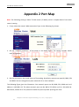
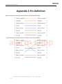
1
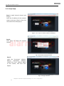
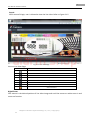
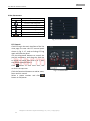
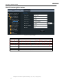
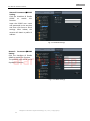
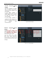
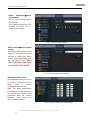
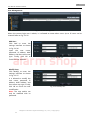
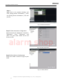
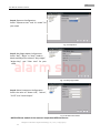
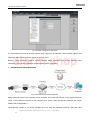
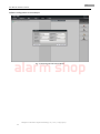
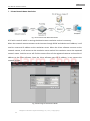
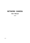
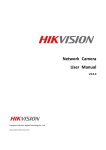
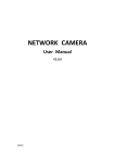
Network Camera User Manual alarm shop V3.0.0 Hangzhou Hikvision Digital Technology Co., Ltd. http://www.hikvision.com 2010-04 Thank you for purchasing our product. If there are any questions, or requests, please do not hesitate to contact the dealer. This manual applies to Network Camera. This manual may contain several technical incorrect places or printing errors, and the content is subject to change without notice. The updates will be added to the new version of this manual. We will readily improve or update the products or procedures described in the manual. DISCLAIMER STATEMENT “Underwriters Laboratories Inc. (“UL”) has not tested the performance or reliability of the security or signaling aspects of this product. UL has only tested for fire, shock or casualty hazards as outlined in UL’s Standard(s) for Safety, UL60950-1. UL Certification does not cover the performance or reliability of the security or signaling aspects of this product. UL MAKES NO REPRESENTATIONS, WARRANTIES OR CERTIFICATIONS WHATSOEVER REGARDING THE PERFORMANCE OR RELIABILITY OF ANY SECURITY OR SIGNALING RELATED FUNCTIONS OF THIS PRODUCT.” alarm shop 1 User Manual of Network Camera Safety Instruction These instructions are intended to ensure that the user can use the product correctly to avoid danger or property loss. The precaution measure is divided into ‘Warnings’ and ‘Cautions’: Warnings: Serious injury or death may be caused if any of these warnings are neglected. Cautions: Injury or equipment damage may be caused if any of these cautions are neglected. Warnings Follow these safeguards to Cautions Follow these precautions to prevent serious injury or death. prevent potential injury or material damage. Warnings: 1. In the use of the product, you must strictly comply with the electrical safety regulations of the alarm shop nation and region. 2. Source with DC 12V or AC 24V (Whether supporting AC 24V lies on the specific camera model) according to the IEC60950-1 standard. Please refer to technical specifications for more details. 3. Do not connect several devices to one power adapter as an adapter overload may cause over-heating and can be a fire hazard. If use the POE as the power supply, please make sure that the POE Switch have the sufficient power .(Whether supporting PoE power supply lies on the specific camera model) 4. Please make sure that the plug is firmly inserted into the power socket. 5. When the product is installed on a wall or ceiling, the device should be firmly fixed. 6. If smoke, odor, or noise rise from the device, turn off the power at once and unplug the power cable, then contact the service center. 7. If the product does not work properly, please contact your dealer or the nearest service center. Never attempt to disassemble the camera yourself. (We shall not assume any responsibility for problems caused by unauthorized repair or maintenance.) Hangzhou Hikvision Digital Technology Co., Ltd. | Copyright © 2 User Manual of Network Camera Notice: 1. Make sure the power supply voltage is correct before using the camera. 2. Do not drop the camera or subject it to physical shock. 3. Do not touch sensor modules with fingers. If cleaning is necessary, use a clean cloth with a bit of ethanol and wipe it gently. If the camera will not be used for an extended period of time, put on the lens cap to protect the sensor from dirt. 4. Do not aim the camera at the sun or extra bright places. A blooming or smear may occur otherwise (which is not a malfunction however), and affecting the endurance of sensor at the same time. 5. The sensor may be burned out by a laser beam, so when any laser equipment is being used, make sure that the surface of the sensor will not be exposed to the laser beam. 6. Do not place the camera in extremely hot or cold temperatures (the operating temperature alarm shop should be between -10°C ~ +60°C, dusty or damp locations, and do not expose it to high electromagnetic radiation. 7. To avoid heat accumulation, good ventilation is required for a proper operating environment. 8. While shipping, the camera should be packed in its original packing, or packing of the same texture. 9. Regular part replacement: a few parts (e.g. electrolytic capacitor) of the equipment should be replaced regularly according to their average life time. The average time varies because of differences between operating environment and usage history, so regular checking is recommended for all users. Please contact with your dealer for more details. Hangzhou Hikvision Digital Technology Co., Ltd. | Copyright © 3 User Manual of Network Camera Table of Contents Chapter 1 Network Camera Connection....................................................................... 1 Chapter 2 Network Access ........................................................................................... 3 2.1 Access over IE Browser ..................................................................................... 3 2.1.1 Live View ................................................................................................. 4 2.1.2 Parameters Configuration ........................................................................ 7 2.2 Access over Client Software............................................................................ 19 2.2.1 Client Software Installation.................................................................... 19 2.2.2 Live View ............................................................................................... 21 2.2.3 Sensor Parameters Configuration .......................................................... 24 alarm shop Chapter 3 Access over Internet .................................................................................. 28 3.1 Access network camera with static IP ....................................................... 28 3.2 Access network camera with dynamic IP .................................................. 29 Appendix 1 SADP Introduction ................................................................................... 33 Appendix 2 Port Map ................................................................................................. 35 Appendix 3 Pin Definition .......................................................................................... 37 Hangzhou Hikvision Digital Technology Co., Ltd. | Copyright © 1 User Manual of Network Camera Chapter 1 Network Camera Connection Two methods can be used to connect between network camera and PC, shown as below: Fig. 1.1 Cross Line Connection alarm shop Fig. 1.2 Direct Line Connection Before visiting network camera over network, user should acquire its IP address first. SADP is a software tool which can automatically detect Hikvision’s network device in the LAN and give the device’s information like IP address, mask, port number, device serial number, software version, etc., shown as Fig. 1.3. Hangzhou Hikvision Digital Technology Co., Ltd. | Copyright © 2 User Manual of Network Camera Fig. 1.3 Select the device, and set its IP address and mask at the same network segment with the PC. For the detailed introduction of SADP, please refer to Appendix 1. Note: The network camera is set with the factory default IP address of “192.0.0.64”, the port of “8000”, the super user name of “admin” and the password of “12345”. alarm shop Hangzhou Hikvision Digital Technology Co., Ltd. | Copyright © 3 User Manual of Network Camera Chapter 2 Network Access After hardware installation, user can view live video and configure parameters for the network camera, including IP address, subnet mask and port number, etc. The following two methods can be used to access the camera: 1. View live video and configure parameters over IE browser. 2. View live video and configure parameters over client software. 2.1 Access over IE Browser Before access to the camera over IE browser, user should adjust the security level. alarm shop Open the IE browser, and set the security level to [Low] in [Tools/ InternetOptions/Security/Custom Level...], and enable or prompt Activex Control and Plug-in directly as well. Fig. 2.1.1 Adjust the Security Level Hangzhou Hikvision Digital Technology Co., Ltd. | Copyright © 4 User Manual of Network Camera 2.1.1 Live View Step 1: Install Active-X Control and Plug-in. Input the IP address of the network camera and press [Enter], then click the mention box that pop up. Figure 2.1.2 Tips of ActiveX Control Installation alarm shop Step 2: Click [Run] to install the ActiveX control. Fig. 2.1.3 Install the ActiveX Control Step 3: Input the “Username” (default: admin), “Password” (default: 12345) and “Port” (default: 8000) of the camera, and then click [Login]. Fig. 2.1.4 Login Interface Hangzhou Hikvision Digital Technology Co., Ltd. | Copyright © 5 User Manual of Network Camera Step 4: After successful login, user is allowed to view the live video. Refer to Figure 2.1.5. alarm shop Fig. 2.1.5 Live View Page Icons on Live View Page: Icon Description Full-screen display mode Exit full-screen display mode Start Preview Stop Preview Capture Picture Start/Stop Record Digital Zoom Video Parameters Digital Zoom: Click mouse in the desired position of live video image and scroll the mouse to realize zoom in and zoom out function. Hangzhou Hikvision Digital Technology Co., Ltd. | Copyright © 6 User Manual of Network Camera Video Parameters: Icon Description Brightness: 0~100 configurable Contrast: 0~100 configurable Saturation: 0~100 configurable Hue: 0~100 configurable Gain: 0~100 configurable Exposure time: 0~40000 configurable Restore default Fig. 2.1.6 Video Parameters PTZ Control: Click PTZ tag in the main interface of the live view page to enter the PTZ control panel shown in Fig. 2.1.7, and re-clicking PTZ tag again will hide the panel. Use the directional buttons to control the pan/tilt movement, and drag the slide bar to adjust the speed from level 1 to 7, with the default speed of level 4. alarm shop Click button to start auto scan, and re-click it to stop scan. Click the functional buttons to realize zoom, focus and iris control. Select a preset number and click button to call preset. Fig. 2.1.7 PTZ Control Hangzhou Hikvision Digital Technology Co., Ltd. | Copyright © 7 User Manual of Network Camera 2.1.2 Parameters Configuration Click Configuration to enter the Parameters Configuration interface. 2.1.2.1 Local Configuration alarm shop Fig. 2.1.8 Local Configuration Local Configuration: Parameters Description Protocol type TCP and UTP selectable Stream type Main stream and Sub stream selectable Display mode Package file size Full-screen, 4:3 mode, 16:9 mode or adjustable to resolution 128M, 256M, 512M selectable Transmission Shortest delay mode, good real-time, normal real-time and fluency and good performance fluency options selectable Save record file as The default directory for saving record files is C: \OCXRecordFiles, which can be modified by user Save captured picture as The default directory for saving captured files is C:\OCXBMPCaptureFiles, which can be modified by user Hangzhou Hikvision Digital Technology Co., Ltd. | Copyright © 8 User Manual of Network Camera 2.1.2.2 Remote Configuration Basic Information: In the Basic Information settings interface, user is allowed to set the Device Name and Device ID, as well as view the information of IP camera, including Device Description, Device Location, MAC address, Device Type, Device SN, Firmware Version, and U-boot Version. Fig. 2.1.9 Basic Information Channel ParametersDisplay Setting: According to different requirements, enable the display of Date&Time and Week by clicking the checkbox. Different date formats can be selected. The OSD Status can be set to transparent & flickering, transparent & unflickering, nontransparent & flickering, or nontransparent & unflickering. alarm shop Fig. 2.1.10 Display Settings Hangzhou Hikvision Digital Technology Co., Ltd. | Copyright © 9 User Manual of Network Camera Channel ParametersVideo Settings: Fig. 2.1.11 Video Settings alarm shop Parameter Description Stream type Select stream type to Main stream or Sub stream Resolution Image Quality Select the resolution for your need, Select image quality to Highest, High, Medium, Low, Lower or Lowest Stream Type Select the bitrate type to Constant bitrate or Variable bitrate Max. Bitrate Select or custom bitrate according to the resolution Multicast RTSP Port Set the multicast address, with the default multicast of 0.0.0.0 Set the RTSP port, with the default RTSP port of 554 Hangzhou Hikvision Digital Technology Co., Ltd. | Copyright © 10 User Manual of Network Camera Channel ParametersMotion Detection Setting: Select the checkbox of Enable motion detection to enable this function. Zone Settings: Click Start draw button to draw motion detection zone by clicking and dragging the mouse in the live video image. User is allowed to draw multiple motion detection zones in the same picture. When all zones have been set, click Stop draw to finish drawing. Sensitivity: The sensitivity level can be set to 0, 1, 2, 3, 4 and 5. When it is set to 0, the sensitivity is disabled. Linkage: The Linkage method can be selected to either Email link or Trigger alarm output. Fig. 2.1.12 Motion Detection Zone Settings alarm shop Fig. 2.1.13 Motion Detection Linkage Settings Hangzhou Hikvision Digital Technology Co., Ltd. | Copyright © 11 User Manual of Network Camera Channel ParametersText Overlay Setting: Input the characters in the Text Information box and define the OSD location in the image by setting the XPosition and YPosition, and then select the checkbox of OSD Text. After clicking Save to finish the settings, the defined title will be displayed on the image. Note: The values of XPosition and YPosition refer to the position relative to the origin as the upper left corner of the image. Fig. 2.1.14 Text Overlay Settings alarm shop Network ParametersNetwork Setting: Set the IP Address, Subnet Mask, Gateway and DNS Server of the network camera. Fig. 2.1.15 Network Settings Hangzhou Hikvision Digital Technology Co., Ltd. | Copyright © 12 User Manual of Network Camera Network ParametersPPPOE Setting: Click the checkbox of Enable PPPOE to enable this function. Input the PPPOE user name and password in the text box and then click Save to finish settings. After reboot, the camera will obtain a public IP address. Fig. 2.1.16 PPPOE Settings Network ParametersDDNS Setting: Click the checkbox of Enable DDNS to enable this function. The protocol type can be set to DynDNS or IPServer. alarm shop Fig. 2.1.17 DDNS Settings Hangzhou Hikvision Digital Technology Co., Ltd. | Copyright © 13 User Manual of Network Camera If the protocol type is selected to DynDNS, please input the Server Address, e.g., members.dyn dns. org. The User Name and Password refer to the user name and password registered in the DynDNS website. The Device Name refers to the domain name applied in the DynDNS website. Fig. 2.1.18 DynDNS Settings If the protocol type is selected to IPServer, please input the Server Address of the IPServer. alarm shop Fig. 2.1.19 IPServer Settings Hangzhou Hikvision Digital Technology Co., Ltd. | Copyright © 14 User Manual of Network Camera Network ParametersDDNS Setting: Click the checkbox of Enable NTP to enable this function. Input the Server Address and Port of NTP. If the public network is applied, please input the NTP Server Address with provision of time sync service, e.g., 210.72.145.44. In the private network is applied, the NTP software can be used to establish NTP server to achieve time synchronization. Fig.2.1.20 NTP Settings alarm shop Network ParametersE-mail Setting: Through E-mail settings, the alarm message can be sent to the designated E-mail address when alarm event occurs. Input the SMTP server, SMTP port, user name, password, E-mail sender and receiver, and finally click Save to finish E-mail settings. Fig. 2.1.21 E-mail Settings Hangzhou Hikvision Digital Technology Co., Ltd. | Copyright © 15 User Manual of Network Camera Alarm ParametersAlarm Input Setting: Set the type of Relay Status to NC or NO. The Linkage method can be selected to E-mail link or Trigger alarm output. Fig. 2.1.22 Alarm Input Settings Alarm OutputAlarm Output Setting: The Output Delay refers to the length of time that the relay remains in effect after alarm occurs. The output delay time can be set to 5sec, 10sec, 30sec, 1min, 2min, 5min, 10min or Manual (manually disable). alarm shop Fig. 2.1.23 Alarm Output Delay Settings Alarm Deployment Time: The Deployment time can be set to a day of the week or to all week, with a period configurable for each day. Note: The alarm deployment time setting is valid only when the camera has already been configured with the motion detection, alarm input and alarm output functions. Fig. 2.1.24 Alarm Deployment Time Settings Hangzhou Hikvision Digital Technology Co., Ltd. | Copyright © 16 User Manual of Network Camera User Management: Fig. 2.1.25 User Management When the current login user is admin, it is allowed to create other users. Up to 15 users can be created. Refer to Fig. 2.1.25. Add User: Click Add to enter the settings interface as shown in Fig. 2.1.26. Input the user name, password, IP address, MAC address, and then select user type. Finally, click OK to finish the user addition. alarm shop Modify User: Click Modify to enter the settings interface as shown in Fig. 2.1.27. It is allowed to modify the user name, password, IP address, MAC address, and then select user type. Finally, click OK to finish the user modification. Note: The user admin can only be modified with its password. Fig. 2.1.26 Add User Fig. 2.1.27 Modify User Hangzhou Hikvision Digital Technology Co., Ltd. | Copyright © 17 User Manual of Network Camera Remote Upgrade: Click Browse to select the local update file and then click Upgrade to finish remote upgrade. Fig. 2.1.28 Remote Upgrade Restore Default: Select Full Mode or Basic Mode to restore the default settings. Note: The Full Mode refers to restore all parameters to the factory default settings. The Basic Mode refers to restore the parameters to factory default settings except IP address, subnet mask, gateway and port. alarm shop Fig. 2.1.29 Restore Default Reboot Device: Click OK to reboot the network camera. Fig. 2.1.29 Reboot Device 2.1.2.3 Advanced Configuration Note: This chapter is applicable to professional configuration. Hangzhou Hikvision Digital Technology Co., Ltd. | Copyright © 18 User Manual of Network Camera 1: Input the IP address of the network camera and “config”. (Such as http://192.0.0.64/config) 2: Input the “Username” (default: admin), “Password” (default: 12345) and “Port” (default: 8000) of the camera, and then click [Login]. 3: The “Remote config” dialog will pop up, which has more advanced settings including schedule record , HDD settings and so on. alarm shop Please refer to “Client Software-4000(v2.0)_ENG.pdf” for a more detailed parameters configuration. You can find the document in the PC Operating System after the installation of client software 4000 v. 2.0 by selecting “Start”-> “All Programs”-> “client software 4000 v. 2.0”. Hangzhou Hikvision Digital Technology Co., Ltd. | Copyright © 19 User Manual of Network Camera 2.2 Access over Client Software 2.2.1 Client Software Installation Note: It is recommended to use the computer adopting INTEL P3, P4, C4, Core4 CPU, and the Intel chipset motherboard of well-known brands (Asus, Gigabyte, MSI, ECS, and INTEL etc.) to ensure the stability of the system. After testing, the following models of the current graphics cards support the installation of the client software: ATIRadeonX1650, X1600, X1550, X1300, X800, X600, X550, HD2400, HD2600, NVIDIA GeForce 8600GT, 8500GT, 8400GS, 7600, 7300LE, 6600LE, 6200LE, and INTEL915/945G. And the graphics driver must support hardware scaling function. Step 1: Double click ‘Client Software Setup.exe’ in the Windows Operating System. The ‘Preparing Setup’ dialog box will automatically pop up as shown n Fig.2.6. alarm shop Fig. 2.6 Client Software Installation Step 2: Input the User Name and Company Name, and then click Next. Fig.2.7 Customer Information Hangzhou Hikvision Digital Technology Co., Ltd. | Copyright © 20 User Manual of Network Camera Step 3: Select the destination folder and click Next to enter the next step. Fig. 2.8 Ready to Install the Program Step 4: Click Install to start installation till finishing the installation. alarm shop Fig. 2.9 Installation Step 5: Click Finish to close the dialog box. Fig. 2.10 Done Hangzhou Hikvision Digital Technology Co., Ltd. | Copyright © 21 User Manual of Network Camera After the client software has been installed, you can find the remote client software through Start-> Programs from your PC. 2.2.2 Live View After the installation of client software-iVMS-4000(v2.0), there is a short-cut icon named “iVMS 4000(v2.0)” on computer’s desktop. Please double click “iVMS-4000(v2.0)” to run the software. Step 1: Used for the first time: User needs to register an administrator if the software is used for the first time. Input “User name”, “Password”, “Verification”, and click OK, then user can log in as the administrator. Fig. 2.11 Register Administrator alarm shop User login: Input “User”, “Password” and click Login to enter the GUI window of the software. Fig. 2.12 User Login Hangzhou Hikvision Digital Technology Co., Ltd. | Copyright © 22 User Manual of Network Camera Fig. 2.13 GUI window of the software Step 2: Click Setup to enter the configure mode, and then click Device Management. alarm shop Fig. 2.14 Device Management Step 3: Right click the left area, and then click Add Area. Input “Area Name” for your need, and then click OK to add area. Fig. 2.15 Add Area Hangzhou Hikvision Digital Technology Co., Ltd. | Copyright © 23 User Manual of Network Camera Step 4: Right click the area that you add, and then click Add Device to add network camera. Input “Device Name” for your need. Select “Normal IP” from Register Mode. Input network camera’s IP in Device IP, e.g. 192.0.0.64, Port: 8000, User Name: admin, Password: 12345. Select “TCP”, “UTP”, “MCAST” or “RTP” in [Protocol] for your need. Select “Main Stream” or “Sub Stream” in Protocol for your need. Finally, click OK to finish settings. alarm shop Fig. 2.16 Add Device Hangzhou Hikvision Digital Technology Co., Ltd. | Copyright © 24 User Manual of Network Camera Fig. 2.17 Camera Adding Completed Step 5: Click the Preview, and then double click the device name in the left tree to view the live video. alarm shop Fig. 2.18 Preview 2.2.3 Sensor Parameters Configuration For viewing better image, you can set the parameters of the camera, and operate as following: Hangzhou Hikvision Digital Technology Co., Ltd. | Copyright © 25 User Manual of Network Camera Step 1: Right click in the preview window, and click [Config Sensor Parameters…], then the [Config Sensor Parameters…] box will pop up. Fig. 2.19 Sensor Parameters Step 2: Video Parameters Configuration Adjust the value of “Brightness”, “Contrast”, “Saturation”, “Hue”, “Sharpness” and “Gain” for your need, which can be set from 1 to 100. alarm shop Fig. 2.20 Video Parameters Step 3: White Balance Configuration Select the mode to Auto1 or Off for your need. Fig. 2.21 White Balance Hangzhou Hikvision Digital Technology Co., Ltd. | Copyright © 26 User Manual of Network Camera Step 4: Exposure Configuration Select “Exposure time” and “Iris mode” for your need. Fig. 2.22 Exposure Step 5: Day/Night Mode Configuration Select “Day”, “Night” or “Auto” mode in Mode and adjust the value of “Day->Night”, “Night->Day”, and “Filter time” for your need. alarm shop Fig. 2.23 Day/ Night Mode Step 6: Other Parameters Configuration Select the value of “Power Line”, “Mirror”, “E-PTZ” and “Local Output”. Fig. 2.24 Other Parameters NOTE:Different models of the cameras’ maybe have different menus. Hangzhou Hikvision Digital Technology Co., Ltd. | Copyright © 27 User Manual of Network Camera Please refer to “iVMS-4000(v2.0) introductor.pdf” for more detailed parameters configuration. You can find the document in the PC Operating System after the installation of client software 4000 v. 2.0 by selecting “Start”-> “All Programs”-> “iVMS 4000( v. 2.0)” -> “iVMS 4000( v. 2.0)”. alarm shop Hangzhou Hikvision Digital Technology Co., Ltd. | Copyright © 28 User Manual of Network Camera Chapter 3 Access over Internet 3.1 Access network camera with static IP When there is a static IP from an ISP, open some ports (such as 80 and 8000 ports) in the router. Then a user can visit it through a web browser or client software via the internet. The steps for port forwarding are different for each model of router. Please call the router manufacturer for assistance with port forwarding or visit www.portforward.com. Note: Refer to Appendix 2 for a detailed explanation about Port Map. Users can directly connect the network camera to the internet without using a router. alarm shop Fig. 3.1 Access IPC through Router with Static IP Fig.3. 2 Access IPC with Static IP directly For the client software to view the camera, in the adding equipment column, select the normal model, and then fill in the IP info. Hangzhou Hikvision Digital Technology Co., Ltd. | Copyright © 29 User Manual of Network Camera Fig. 3.3 Selecting Normal Mode alarm shop 3.2 Access network camera with dynamic IP Fig. 3.4 Access IPC through PPPoE Dail-up This camera supports the PPPoE auto dial-up function, connecting the camera to a Modem for dial-up access to an ADSL network to get a public IP address; First, through local network access to the network camera, select “Configure”“Right Click the Device”, “Remote Configuration”, and finally select “PPPoE Settings” under “Network Paramters” to fill in the PPPoE user name and password and confirm the password. Please restart the network camera after completion of configuration. Then the network camera can obtain a dynamic IP from an ISP operation business. However, the obtained IP address is dynamically assigned via PPPoE, so the IP address always changes accompanied with modem rebooting. Hangzhou Hikvision Digital Technology Co., Ltd. | Copyright © 30 User Manual of Network Camera Fig. 3.5 PPPoE configuration Dialog box It is inconvenient to view a network camera with a dynamic IP, therefore, users should register with alarm shop a dynamic DNS service provider. (Such as DynDns.com) Domain name resolution contains normal domain name resolution and private domain name resolution. First, we will introduce normal domain name resolution. 1. Normal Domain Name Resolution Fig. 3.6 Normal Domain Name Resolution Apply a domain name from a domain name provider, then view the camera via the applied domain name. If the camera connects to the internet via a router, users should port forward the router. Please refer to Appendix 2. Input domain names in the client software or IE to view the network cameras. Take the client Hangzhou Hikvision Digital Technology Co., Ltd. | Copyright © 31 User Manual of Network Camera software configuration as an example. alarm shop Fig. 3.7 Selecting Normal Domain Mode Hangzhou Hikvision Digital Technology Co., Ltd. | Copyright © 32 User Manual of Network Camera 2. Private Domain Name Resolution Fig. 3.8 Private Domain Name Resolution A PC with a static IP which is running the domain name resolution service is necessary. When the network camera connects to the internet through PPPoE and obtains an IP address, it will send its name and IP address to the resolution server. When the client software connects to the network camera, it will connect to the resolution server and tell the resolution server the expected camera’s name. And the server will find the camera from all the registered cameras and send its IP alarm shop address to the client software. Once the client software gets the IP address, it can connect the network camera. Fig. 3.9 Selecting Private Domain Mode Hangzhou Hikvision Digital Technology Co., Ltd. | Copyright © 33 User Manual of Network Camera Appendix 1 SADP Introduction 1. Brief introduction SADP (Search Active Devices Protocol) is a kind of software which can automatically search network speed dome in LAN. User can modify the IP address, subnet mask and port of the device without visiting IP address of the device. Additionally, password of the super user in this device can be recovered as default. SADP software needs to support SADP, so we should install WinPcap at first, which is placed at the directory of SADP software. 2. Search active devices online After installing WinPcap, double click sadpdlg.exe. The software will start to search active devices in LAN, and device type, IP address, Port number, Device Serial No., subnet mask, MAC address, the number of channels, main control and encoding version and device initiating time are showed in the list, as following: alarm shop 3. Modify device information Select the device that needs modification in the device list, then basic information of the device will be demonstrated in the information column on the right. Click “modify” button to activate IP address, subnet mask, device port editing and password validating box, as follows: Hangzhou Hikvision Digital Technology Co., Ltd. | Copyright © 34 User Manual of Network Camera Select the device that needs modification in the device list, then basic information of the device will be demonstrated in the information column on the right. Click “modify” button to activate IP address, subnet mask, device port editing and password validating box, as following: alarm shop Input new IP address, subnet mask, and port number, and click “save” button. If a dialog pops up, showing “saved successfully”, that means you have modified the configuration information; if “saving failed” turns up, click the “cancel” button to quit it. 4. Recover default password You can reset the password of the super user as “12345” in the case of a lost password. Input certain validation code into the ‘Resume default password’ box, and click ‘OK’ to finish the administrator’s password initiating. Note: Password reset code can be obtained by the technicians from Hikvision after you provide the device Serial NO. Hangzhou Hikvision Digital Technology Co., Ltd. | Copyright © 35 User Manual of Network Camera Appendix 2 Port Map Note: The following setting is about TP-LINK router (TL-R410), which is maybe distinct from other router’s setting. 1. Firstly, select the router’s WAN connection Type. As the following Fig. shows: alarm shop 2. Set the “network parameter” of the router as the below figure. The setting includes subnet mask and gateway. 3. Set the port map in the virtual severs of Forwarding. By default, camera uses port 80, 8000, 554 and 8200. You can change these ports value with IE or client software. The following figure gives the illustration. One camera’s ports are 80, 8000, 554, 8200 and its IP address is 192.168.1.23. The other camera’s ports are 81, 8001, 555, 8201 and IP is 192.168.1.24. Afterwards, enable all or TCP protocols. Enable the port map after pressing the ‘Save’. Hangzhou Hikvision Digital Technology Co., Ltd. | Copyright © 36 User Manual of Network Camera As the settings mentioned above, map the router’s port 80 and 8000 to the network camera at 192.168.1.23; and port 81 and 8001 to the network camera at 192.168.1.24. In this way, user can alarm shop access the 192.168.1.23 through accessing the router’s port 80 and 8000. Note: The port of the network camera cannot conflict with other ports. For example, some router’s web management port is 80. User can amend the router’s or the camera’s port to solve this problem. Hangzhou Hikvision Digital Technology Co., Ltd. | Copyright © 37 User Manual of Network Camera Appendix 3 Pin Definition (1)UTP between the network port of camera and HUB (Direct Cable) alarm shop (2)UTP between the network port of camera and PC (Cross Cable): Hangzhou Hikvision Digital Technology Co., Ltd. | Copyright © 38 User Manual of Network Camera First Choice for Security Professionals alarm shop Hangzhou Hikvision Digital Technology Co., Ltd. | Copyright ©