1
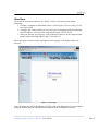
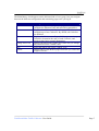
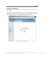
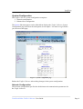
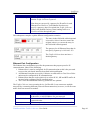
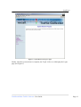
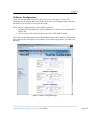
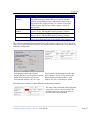
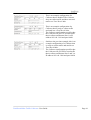
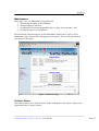
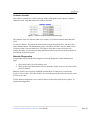
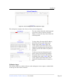
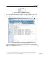
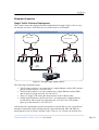
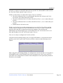
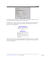
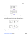
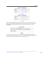
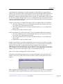
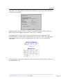
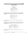
Total Recall Max Traffic Collector
User Guide
Version: 8.1.0
Date: June 2009
Total Recall Max Traffic Collector - User Guide
Page 1
Table of Contents
INTRODUCTION ........................................................................................................................................... 3
Acronyms .............................................................................................................................................. 3
DEVICE DESCRIPTION ................................................................................................................................. 4
Overview ............................................................................................................................................... 4
Ports...................................................................................................................................................... 4
Virtual LANs ......................................................................................................................................... 5
Collectors.............................................................................................................................................. 5
Impact on Exiting Network ................................................................................................................... 5
START HERE ............................................................................................................................................... 6
PASSWORD CONFIGURATION ...................................................................................................................... 8
SYSTEM CONFIGURATION ........................................................................................................................... 9
Network Configuration ......................................................................................................................... 9
Ethernet Port Configuration ............................................................................................................... 10
REBOOTING .............................................................................................................................................. 12
COLLECTOR CONFIGURATION .................................................................................................................. 14
MAINTENANCE ......................................................................................................................................... 17
Collector Status................................................................................................................................... 17
Collector Control ................................................................................................................................ 19
Network Diagnostics........................................................................................................................... 19
Collector Logs..................................................................................................................................... 20
EXAMPLE SCENARIOS ............................................................................................................................... 23
Single Traffic Collector Deployment .................................................................................................. 23
Multiple Traffic Collectors Deployment ............................................................................................. 28
APPENDIX A – SPECIFICATIONS ................................................................................................................ 33
Table of Figures
Figure 1 - Login page .......................................................................................................... 6
Figure 2 - Password Change page ...................................................................................... 8
Figure 3 - System Configuration page ................................................................................ 9
Figure 4 - System Reboot page.......................................................................................... 12
Figure 5 - System Reboot in Progress page ...................................................................... 13
Figure 6- Collector Configuration page ........................................................................... 14
Figure 7 - Maintenance page ............................................................................................ 17
Figure 8 – Collector Status on the Maintenance page ...................................................... 18
Figure 9 – Collector Control on the Maintenance page.................................................... 19
Figure 10– Network Diagnostics on the Maintenance page ............................................. 20
Figure 11– Collector Logs on the Maintenance page ....................................................... 21
Figure 12- Collector Log page.......................................................................................... 21
Figure 13 – Example: Single Traffic Collector................................................................. 23
Figure 14 – Example: Multiple Traffic Collectors ........................................................... 28
Total Recall Max Traffic Collector - User Guide
Page 2
Introduction
The Traffic Collector is a device that can be used to collect H.323, SIP and RTP traffic in
medium to large VoIP networks and deliver the traffic to one or more Total Recall Max
units.
For small VoIP networks a Total Recall Max unit with its very useful embedded traffic
collection capability may suffice.
The Traffic Collector has a web based interface which works with all standard web
browsers such as Internet Explorer and Firefox. This publication describes the interface
and how it can be used to configure and monitor the operation of a Traffic Collector.
Acronyms
DNS
GUI
IP
LAN
RTP
SIP
H.323
TCP
UDP
VLAN
VoIP
Domain Name Server
Graphical User Interface
Internet Protocol
Local Area Network
Real Time Protocol
Session Initiation Protocol
Suite of VoIP protocols
Transmission Control Protocol
User Datagram Protocol
Virtual LAN
Voice over IP
Total Recall Max Traffic Collector - User Guide
Page 3
Device Description
Overview
The Traffic Collector is a device that can be used to collect H.323, SIP and RTP traffic in
medium to large VoIP networks and deliver the traffic to one or more Total Recall Max
units.
The Traffic Collector is very attractive option for distributed networks, consisting of
multiple subnets. Multiple Traffic Collectors can be placed in strategic places on the
network, where H.323, SIP and RTP traffic can be captured and delivered to one or more
Total Recall Max recording units. The subsequent diagram is an example of such
scenario.
Internet Provider
VoIP Provider
Main Office
Branch Office
SW3
SW1
SW4
SW2
`
`
IP Phones
IP Phones
`
`
PCs
PCs
IP
Collected Traffic + IP
Collected Traffic
SW5
Traffic Collector 2
Traffic Collector 1
VoIP
IP
TR-MAX
For small VoIP networks a Total Recall Max unit with its very useful embedded traffic
collection capability may suffice.
Ports
Each Traffic Collector comes with four (4) Ethernet ports and is capable of collecting
H.323, SIP and RTP traffic on all ports. However, it may be appropriate, and desirable, to
reserve one of the ports for sending H.323, SIP and RTP traffic to Total Recall Max units.
Total Recall Max Traffic Collector - User Guide
Page 4
Note that access to the web based interface is only available through Ethernet Port 1.
Virtual LANs
The Ethernet Ports can connect to a VLAN network (IEEE 802.1Q). To enable this
feature, specify the VLAN ID during the port configuration.
Collectors
Up to four (4) individual Collectors can be active on every Traffic Collector. The
Collectors are the engines that collect traffic from one or more Ethernet Ports and send
the traffic to Total Recall Max units.
Each Collector can send traffic to one Total Recall Max; however, more that one
Collector can send traffic to the same Total Recall Max.
Collectors use a proprietary protocol on top of the TCP or the UDP protocol to send
traffic to a Total Recall Max. UDP is an unreliable protocol and packets can get lost in
the network for various reasons. As a result, avoid using UDP, or use it only for low
traffic volumes – up to 10 active calls.
Impact on Exiting Network
The Traffic Collector gives enhance flexibility to the Total Recall Max. However, it will
have impact on existing network if it connects Traffic Collectors to Total Recall Maxes.
The impact is an increase of the amount of traffic that the network needs to support.
The Collectors basically send a copy of the H.323, SIP and RTP traffic that they collect
to a Total Recall Max. This has the effect of doubling the H.323, SIP and RTP traffic that
the network needs to transport.
Use a separate network between the Traffic Collectors and Total Recall Maxes to
minimise the impact on the existing network.
Total Recall Max Traffic Collector - User Guide
Page 5
Start Here
To access the web based interface of a Traffic Collector for the first time do the
following:
1. Connect a computer to the Ethernet Port 1 of the Traffic Collector using a crossover LAN cable.
2. Configure the LAN port that you are using on your computer with the following
static IP address: 192.168.3.100, and network mask: 255.255.255.0.
3. Start your favorite web browser, such as Internet Explorer, on the computer and
point it to the following address: http://192.168.3.82.
The Login page, as shown on the subsequent screen capture, will display in the web
browser.
Figure 1 - Login page
You can change the default IP address (192.168.3.82) of the Ethernet Port 1 to an address
using the System menu as explained in the Ethernet Port Configuration section.
Total Recall Max Traffic Collector - User Guide
Page 6
The Main Menu, which appears on the left-hand side of every page, lets you navigate
between the different configuration and monitoring pages once you log in.
Main Menu Link
System
Collectors
Maintenance
Change Password
Exit
Reboot
Description
Displays the System Configuration page which lets you
configure the Ethernet Ports and networking parameters.
Displays the Collector Configuration page which lets you
configure up to four Collectors. By default, all Collectors
are disabled.
Displays the Maintenance Page which lets you start/stop
Collectors, determine the state of each Collector, and
perform some basic network diagnostics.
Displays the Password Change page which lets you change
the password for the “admin” user.
Select this link to log out the “admin” user.
Displays the System Reboot page which lets you reboot the
Traffic Collector.
Total Recall Max Traffic Collector - User Guide
Page 7
Password Configuration
The Traffic Collector has one user that is allowed to gain access to the web interface. The
user is “admin”.
The default password for the user “admin” is “admin”. You can change this password by
using the Password Change page shown on the subsequent screen capture. To access this
page click on the Change Password link that appears on the Main Menu.
Figure 2 - Password Change page
Total Recall Max Traffic Collector - User Guide
Page 8
System Configuration
The Traffic Collector system configuration comprises:
1. Network configuration
2. Ethernet Port configuration
The System link that appears on the Main Menu displays the Traffic Collector System
Configuration page shown on the subsequent screen capture. You need to log in before
you can access this page.
Figure 3 - System Configuration page
Reboot the Traffic Collector after making changes in the system configuration.
Network Configuration
The network configuration specifies the default network communication parameters for
the Traffic Collector.
Total Recall Max Traffic Collector - User Guide
Page 9
Parameter
Default Gateway
Description
This is the default gateway for IP traffic on the network
that the Traffic Collector is part of.
Note that you can specify a gateway for IP traffic for each
Ethernet Port. However, if an Ethernet Port does not
specify a gateway, then (if required) the Traffic Collector
will use the Default Gateway when sending traffic to a
Total Recall Max through the port.
The subsequent examples explain different configuration scenarios.
The entry in the field with red background
is incorrect. Select Cancel to restore the
original value(s), or correct the entry in
the field with red background.
The gateway for all Ethernet Ports that do
not specify a gateway is 192.168.3.253.
The Traffic Collector does not have a
default gateway.
Ethernet Port Configuration
The Ethernet Port configuration specifies the parameters that prepare ports for IP
communication. Observe the following:
1. Ethernet Port 1 must be configured for IP communication as this is the port used
to access the web based interface described in this publication.
2. All Ethernet Ports that are used by Collectors to send traffic to Total Recall Max
units must be configured for IP communication.
3. Ethernet Ports that are used exclusively to collect H.323, SIP and RTP traffic do
not need to be configured for IP communication.
4. The VLAN ID and Default Gateway parameters are optional.
The Traffic Collector is not a routing device for IP traffic. It can connect to multiple
networks (by connecting different ports to different networks); however, it will not route
traffic from one network to another.
Parameter
IP Address
Network Mask
Gateway
Description
The IP address that the port will use for IP communication.
It should be a valid IP address for your network.
The network mask that the port will use for IP
communication.
This is an optional parameter and it specifies the default IP
Total Recall Max Traffic Collector - User Guide
Page 10
VLAN ID
traffic gateway for all IP communication through the port.
This is an optional parameter and it specifies the 802.1Q
tag used on the virtual LAN that the port connects to.
The subsequent examples explain different configuration scenarios.
The entry in the field with red background
is incorrect. Select Cancel to restore the
original value(s), or correct the entry in
the field with red background.
This is an example of a basic Ethernet
Port configuration. The port has an IP
address (192.168.3.83) and is connected
to the 192.168.3.0/24 network.
All traffic for other networks will use the
Default Gateway (see Network
Configuration). The port is not part of a
VLAN.
This is an example of an Ethernet Port
configuration that is similar to the
previous one; except that all traffic for
other networks will use the specified
Gateway (192.168.3.253).
This is an example of a basic Ethernet
Port configuration for a VLAN. The port
has an IP address (192.168.3.83) and is
connected to the 192.168.3.0/24 network
with VLAN ID 100.
All traffic for other networks will use the
Default Gateway (see Network
Configuration).
Total Recall Max Traffic Collector - User Guide
Page 11
Rebooting
To reboot the Traffic Collector, select the Reboot link on the Main Menu. This shows the
System Reboot page which is shown on the subsequent screen capture.
Figure 4 - System Reboot page
Press the Reboot button to initiate the reboot sequence. The Traffic Collector will display
the System Reboot in Progress page, which is shown on the subsequent screen capture,
while it is rebooting.
Total Recall Max Traffic Collector - User Guide
Page 12
Figure 5 - System Reboot in Progress page
Finally, when the system reboot is complete, the Traffic Collector will display the Login
page (see Figure 1).
Total Recall Max Traffic Collector - User Guide
Page 13
Collector Configuration
Up to four (4) individual Collectors can be active on each Traffic Collector. The
Collectors are the engines that collect traffic from one or more Ethernet Ports and send
the traffic to one or more Total Recall Max units.
The Collector configuration for each Collector specifies:
1. the Ethernet Port(s) that the Collector should use to collect H.323, SIP and RTP
traffic; and
2. the Total Recall Max that will receive the H.323, SIP and RTP traffic.
The Collectors link that appears on the Main Menu displays the Collector Configuration
page shown on the subsequent screen capture. You need to log in before you can access
this page.
Figure 6- Collector Configuration page
Total Recall Max Traffic Collector - User Guide
Page 14
Parameter
Total Recall
Protocol
Total Recall IP
Address
Total Recall Port
Ethernet Port
Description
Collectors use a proprietary protocol on top of the TCP or
the UDP protocol to send traffic to a Total Recall Max.
UDP is an unreliable protocol and packets can get lost in
the network for various reasons. As a result, avoid using
UDP, or use it only for low traffic volumes – up to 10
active calls.
This is the IP address of the Total Recall Max that will
receive H.323, SIP and RTP traffic from the Collector.
This is the TCP (or UDP) port the Total Recall Max uses to
receive H.323, SIP and RTP traffic from the Collector.
The Collector will collect H.323, SIP and RTP traffic on
one or more Ethernet Ports as specified by this parameter.
The Collector configuration must match the VoIP Settings of the Total Recall Max that
will receive traffic from the Collector. The following screen captures are an example of a
matching configuration.
VoIP Settings (inside the red box)
specify that the Total Recall Max expects
traffic from collectors on TCP port
10020 and IP address 192.168.3.196.
The Collector configuration specifies that
the Collector will use TCP to send traffic
that it collects on Ethernet Port 1 to IP
address 192.168.3.196 and port 10020.
The subsequent examples explain different configuration scenarios.
The entry in the field with red background
is incorrect. Select Cancel to restore the
original value(s), or correct the entry in
the field with red background.
Total Recall Max Traffic Collector - User Guide
Page 15
This is an example configuration of a
Collector that is disabled. The Collector
does not collect traffic and does not send
traffic to a Total Recall Max.
This is an example configuration of a
Collector that is ready to collect traffic
and send it to a Total Recall Max.
The Collector configuration specifies that
the Collector will use TCP to send traffic
that it collects on Ethernet Port 1 to IP
address 192.168.3.196 and port 10020.
Similar to the previous example, this is an
example configuration of a Collector that
is ready to collect traffic and send it to a
Total Recall Max.
The Collector configuration specifies that
the Collector will use UDP to send traffic
that it collects on Ethernet Port 2 and 3 to
IP address 192.168.3.200 and port 10020.
Total Recall Max Traffic Collector - User Guide
Page 16
Maintenance
The Traffic Collector Maintenance page allows for:
1. determining the status of the Collectors;
2. starting/stopping Collectors;
3. performing basic network diagnostics such as `ping` and `traceroute`; and
4. viewing the logs for each Collector.
The Maintenance link that appears on the Main Menu displays the Traffic Collector
Maintenance page shown on the subsequent screen capture. You need to log in before
you can access this page.
Figure 7 - Maintenance page
Collector Status
The collector status area, which is shown on the subsequent screen capture, displays the
operational status of each Collector.
Total Recall Max Traffic Collector - User Guide
Page 17
Figure 8 – Collector Status on the Maintenance page
Parameter
Collector
State
Connection Status
Description
The Collector instance.
Shows the operational state of the corresponding Collector
instance. Possible states are:
• Not used – the Collector is not used to collect
traffic.
• Stopped – the Collector is ready (configured) to
collect traffic and send it to a Total Recall Max;
however, it is not active.
• Running – The Collector is active and it collects
traffic. See the Connection Status to determine
whether the Collector is sending the traffic it
collects to a Total recall Max.
Shows the status of the connection between the Collector
and the associated Total Recall Max. Possible states are:
• Connecting … - the Collector is attempting to
establish a connection with the associated Total
Recall Max.
• “tcp 0 0 <ip address>:<port> <ip address>:<remote
port>” – the Collector is sending traffic to the
associated Total Recall Max via TCP. The first <ip
address>:<port> pair is the IP address and port on
the Traffic Collector, while the second is the IP
address and port on the Total Recall Max.
• “udp 0 0 <ip address>:<port> <ip
address>:<remote port>” – the Collector is sending
traffic to the associated Total Recall Max via UDP.
The first <ip address>:<port> pair is the IP address
and port on the Traffic Collector, while the second
is the IP address and port on the Total Recall Max.
•
The Collector status does not update automatically. Click on the Update button to get an
up to date status.
Total Recall Max Traffic Collector - User Guide
Page 18
Collector Control
The collector control area, which is shown on the subsequent screen capture, contains
controls to start, stop and restart each of the Collectors.
Figure 9 – Collector Control on the Maintenance page
The controls work on Collectors that are in a state (see Collector Status) other than Not
Used.
To start a Collector, first select the Start action from the drop down box, and then click
on the Submit button. The Maintenance page will update and show the new status of the
Collector in the Collector Status area. The steps to stop and re-start a Collector are
exactly the same, except select the Stop and Restart action respectively in the drop down
box instead of the Start action.
Network Diagnostics
It is possible to perform the following basic network diagnostics on the Maintenance
page:
1. ping a host with a given IP address; and
2. discover the route that packets will take from the Traffic Collector to a host with a
given IP address.
Both are useful ways to quickly establish whether there is connectivity between the
Traffic Collector and a Total Recall Max or a network gateway that must be used to reach
a Total Recall Max.
Use the network diagnostics area, which is shown on the subsequent screen capture, to
perform the diagnostics.
Total Recall Max Traffic Collector - User Guide
Page 19
Figure 10– Network Diagnostics on the Maintenance page
The subsequent examples show the use of the network diagnostics.
The entry in the field with red background
is incorrect. Select Cancel to clear the
fields, or correct the entry in the field with
red background.
To ping a host, first enter the IP address,
then select the Ping radio button and
finally click on the Submit link. The
screen capture on the side shows what
should be a familiar result when the host
with the specified IP address responds to
the ping.
To discover the route that packets will
take to a host, first enter the IP address,
then select the Traceroute radio button
and finally click on the Submit link. The
screen capture on the side shows what
should be a familiar result of a route to a
host.
Collector Logs
The collector logs area, which is shown on the subsequent screen capture, contains links
to the logs for each of the Collectors.
Total Recall Max Traffic Collector - User Guide
Page 20
Figure 11– Collector Logs on the Maintenance page
To view the log of a Collector simply click on the correct link. The Traffic Collector will
display the content of the Collector’s log in a Collector Log page, which is shown on the
subsequent screen capture.
Figure 12- Collector Log page
The Collector Log page does not update automatically. Use the browser’s Refresh button
to get an up to date information in the log.
Total Recall Max Traffic Collector - User Guide
Page 21
Total Recall Max Traffic Collector - User Guide
Page 22
Example Scenarios
Single Traffic Collector Deployment
This scenario shows the deployment and configuration of a single Traffic Collector on a
site that has two floors. Each floor has its own network for VoIP traffic.
Single Traffic Collector Deployment
VoIP Provider
Internet Provier
R1
R2
SW4
SW3
SW1
SW2
Mirror
Mirror
`
Floor 1 IP Phones
Floor 2 IP Phones
`
Floor 1 PCs
IP
Traffic
Collector
`
`
`
`
Floor 2 PCs
SW5
Collected VoIP
VoIP
IP
TR-MAX
Figure 13 – Example: Single Traffic Collector
The following assumptions apply:
• The IP phones on floor 1 are connected to a single Ethernet switch (SW1) and are
part of a single network: 192.168.1.0/24.
• The IP phones on floor 2 are also connected to a single Ethernet switch (SW2)
and are part of a single network: 192.168.2.0/24.
• There is a single VoIP router (R1) that connects to the VoIP provider.
• Similar to the IP phones, the PCs on floor 1 are connected to a single Ethernet
switch (SW3) and are part of a single network: 192.168.3.0/24. The default
gateway on this network is 192.168.3.253.
After doing some preliminary network assessment we decide that it is not a good idea to
introduce extra traffic in the existing network (especially through SW1 and SW2) by
deploying the Total Recall Max and the Traffic Collector. As a result, our decision is to
Total Recall Max Traffic Collector - User Guide
Page 23
introduce a separate switch (SW5) that will carry the H.323, SIP and RTP traffic between
the Total Recall Max and the Traffic Collector.
Further, our decision is to connect the Traffic Collector as follows:
• We will use Ethernet Port 1 to send all traffic that the unit collects to the Total
Recall Max. We connect this port to SW5.
• We will use Ethernet Port 2 to collect all traffic on floor 1, so we connect this port
to SW1.
• We will use Ethernet Port 3 to collect all traffic on floor 1, so we connect this port
to SW2.
• Ethernet Port 4 will not be used.
Finally, our decision is to provide management access to the Total Recall Max and the
Traffic Collector from the 192.168.3.0/24 network. As a result, we make a connection
between SW5 and SW3 as shown on the previous diagram. Also, the network
administrator was kind enough to give us IP address 192.168.3.196 for the Total recall
Max and IP address 192.168.3.82 for the Traffic Collector.
Now we are ready to configure the Total Recall Max.
Using the Network Settings dialog, first we assign an IP address, a network mask and a
gateway to the LAN 1 port of the Total Recall Max as shown on the following screen
capture.
Then, using the VoIP Settings dialog, we configure the Total Recall Max to accept H.323,
SIP and RTP traffic on the IP address previously assigned to the LAN 1 port, and TCP
port 10020. The configuration is shown on the subsequent screen capture (the parameters
inside the red rectangle).
Total Recall Max Traffic Collector - User Guide
Page 24
At this point the Total Recall Max is ready to accept traffic from the Traffic Collector. So
we can proceed with the configuration of the Traffic Collector.
The Ethernet Port 1 on the Traffic Collector must be configured for IP communication as
it will be used to send traffic to the Total Recall Max. The subsequent screen capture
shows the correct configuration.
Ethernet Port 2 and 3 do not need to be configured for IP communication as we only plan
to use them to collect H.323, SIP and RTP traffic. The subsequent screen capture shows
the correct configuration.
Total Recall Max Traffic Collector - User Guide
Page 25
Now is the time to reboot the Traffic Collector – we made changes to the System
Configuration.
Once the Traffic Collector is functional again, we can proceed with the configuration of
the Collectors. We only need two Collectors so we will use Collector 1 and 2. It is
possible to use one Collector as well, but for the purpose of this example we will use two.
The subsequent screen capture shows the correct configuration.
We also disable Collector 3 and 4. The subsequent screen capture shows the correct
configuration.
Total Recall Max Traffic Collector - User Guide
Page 26
Finally, using the Maintenance page, we start Collector 1 and 2. We can observe the
status of the connections on the same page. The subsequent screen capture shows what
the status will look like if the Traffic Collector connects to the Total Recall Max
successfully.
One last note: the Traffic Collector will collect H.323, SIP and RTP traffic only if it
“sees” the traffic on Ethernet Port 2 and 3. This is only possible if SW1 and SW2 mirror
all VoIP traffic to their ports that connect to the Traffic Collector.
Total Recall Max Traffic Collector - User Guide
Page 27
Multiple Traffic Collectors Deployment
This scenario shows the deployment and configuration of multiple Traffic Collectors, one
at each site. Each site has its own network for VoIP traffic.
Internet Provider
VoIP Provider
Main Office
Branch Office
SW3
SW1
SW4
SW2
`
`
IP Phones
IP Phones
`
`
PCs
PCs
IP
Collected Traffic + IP
Collected Traffic
SW5
Traffic Collector 2
Traffic Collector 1
VoIP
IP
TR-MAX
Figure 14 – Example: Multiple Traffic Collectors
The following assumptions apply for the Main Office site:
• The IP phones are connected to a single Ethernet switch (SW1) and are part of a
single network: 192.168.1.0/24.
• There is a single VoIP router (R1) that connects to the VoIP provider.
• Similar to the IP phones, the PCs are connected to a single Ethernet switch (SW2)
and are part of a single network: 192.168.3.0/24. The default gateway on this
network is 192.168.3.253.
The following assumptions apply for the Branch Office site:
• The IP phones are connected to a single Ethernet switch (SW3) and are part of a
single network: 192.168.2.0/24.
• There is a single VoIP router (R1) that connects to the VoIP provider.
• Similar to the IP phones, the PCs are connected to a single Ethernet switch (SW4)
and are part of a single network: 192.168.4.0/24. The default gateway on this
network is 192.168.4.253.
Total Recall Max Traffic Collector - User Guide
Page 28
After doing some preliminary network assessment we decide that it is a good idea to
minimise the extra traffic in the existing network (especially through SW2 and SW4) by
deploying the Total Recall Max and a Traffic Collector. As a result, our decision is to
introduce a separate switch (SW5) that will carry the H.323, SIP and RTP traffic between
the Total Recall Max and the Traffic Collector at Main Office site. Note that the Traffic
Collector at the Branch Office site will need to use SW4 and SW2 to deliver the traffic it
collects to the Total Recall Max.
Further, our decision is to connect the Traffic Collector at Main Office site as follows:
• We will use Ethernet Port 1 to send all traffic that the unit collects to the Total
Recall Max. We connect this port to SW5.
• We will use Ethernet Port 2 to collect all traffic on this site, so we connect this
port to SW1.
• Ethernet Port 3 and 4 will not be used.
Next, our decision is to connect the Traffic Collector at Branch Office site as follows:
• We will use Ethernet Port 1 to send all traffic that the unit collects to the Total
Recall Max. We connect this port to SW4.
• We will use Ethernet Port 2 to collect all traffic on this site, so we connect this
port to SW3.
• Ethernet Port 3 and 4 will not be used.
Finally, our decision is to provide management access to the Total Recall Max and the
Traffic Collectors from the 192.168.3.0/24 network. As a result, we make a connection
between SW5 and SW3 as shown on the previous diagram. Also, the network
administrator was kind enough to give us IP address 192.168.3.196 for the Total recall
Max, IP address 192.168.3.82 for the Traffic Collector at the Main Office site and the IP
address 192.168.4.100 for the Traffic Collector at the Branch Office site.
Now we are ready to configure the Total Recall Max.
Using the Network Settings dialog, first we assign an IP address, network mask and a
gateway to the LAN 1 port of the Total Recall Max as shown on the following screen
capture.
Then, using the VoIP Settings dialog, we configure the Total Recall Max to accept H.323,
SIP and RTP traffic on the IP address previously assigned to the LAN 1 port, and TCP
Total Recall Max Traffic Collector - User Guide
Page 29
port 10020. The configuration is shown on the subsequent screen capture (the parameters
inside the red rectangle).
At this point the Total Recall Max is ready to accept traffic from the Traffic Collectors.
So we can proceed with the configuration of the Traffic Collectors.
The Ethernet Port 1 on the Traffic Collector at both sites must be configured for IP
communication as it will be used to send traffic to the Total Recall Max. The subsequent
screen capture shows the correct configuration for the Traffic Collector at the Main
Office site.
The subsequent screen capture shows the correct configuration for the Traffic Collector at
the Branch Office site.
Total Recall Max Traffic Collector - User Guide
Page 30
All other Ethernet Ports, on both Traffic Collectors, do not need to be configured for IP
communication as we only plan to use them to collect H.323, SIP and RTP traffic, or not
use them at all. The subsequent screen capture shows the correct configuration for all
other ports.
Now is the time to reboot both Traffic Collectors – we made changes to the System
Configuration.
Once the Traffic Collectors are functional again, we can proceed with the configuration
of the Collectors on each. We only need one Collector on each so we will use Collector 1.
The subsequent screen capture shows the correct configuration for Collector 1 at the
Main Office site.
The subsequent screen capture shows the correct configuration for Collector 1 at the
Branch Office site.
Total Recall Max Traffic Collector - User Guide
Page 31
Yes, the configuration for both Collectors is the same. That is because both will send the
H.323, SIP and RTP traffic that they collect to the same Total recall Max, and both are
using Ethernet Port 2 to collect H.323, SIP and RTP traffic.
We also disable all other Collectors (2, 3 and 4) on both Traffic Collectors. The
subsequent screen capture shows the correct configuration for all of disabled Collectors.
Finally, using the Maintenance page, we start Collector 1 on both Traffic Collectors. We
can observe the status of the connections on the same page. The subsequent screen
capture shows what the status will look like if the Traffic Collector at the Main Office
site connects to the Total Recall Max successfully. The result should be the same for the
Traffic Collector at the Branch Office site.
One last note: the Traffic Collectors will collect H.323, SIP and RTP traffic only if they
“sees” the traffic on Ethernet Port 2. This is only possible if SW1 and SW3 mirror all
VoIP traffic to their ports that connect to the Traffic Collectors.
Total Recall Max Traffic Collector - User Guide
Page 32
Appendix A – Specifications
Parameter
CPU
Memory
Storage
Network Interface
USB
Console
Power
LED
Operating
Temperature
Storage
Temperature
Chassis Material
Dimensions
Description
On board low power VIA C7 1GHz processor.
512Mb DDR2 400.
CompactFlash 1Gb
Four 10/100Mbps Ethernet ports (RJ-45).
Two ports (disabled).
One port (disabled).
External power adapter 12V, 5A.
Power, HDD, Link/act with transfer rate.
0ºC - 45ºC (32ºF - 113ºF)
-20ºC - 70ºC (-4ºF - 158ºF)
Steel
44mm(1.73˝)(H) x 210mm(8.27˝)(W) x 150mm(5.91˝)(D)
Total Recall Max Traffic Collector - User Guide
Page 33