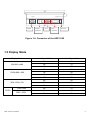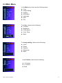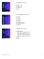
1
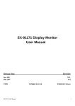
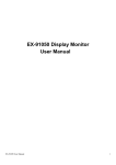
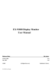
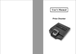
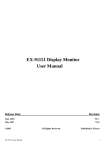
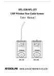
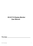
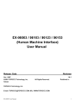
ADP-1050 Display Monitor
User Manual
Release Date
Revision
June 2007
June 2007
®2005 Aplex Technology, Inc.
Taiwan
V0.1
V0.2
All Rights Reserved.
Aplex Technology, Inc.
9F-5, No. 2, Jian Pa Road, Chung Ho City, Taipei County, Taiwan
Tel: 886-2-82262881
Fax: 886-2-82262883
E-mail: [email protected]
www.aplex.com.tw
ADP-1050 User Manual
Published in
URL:
1
Warning!_______________________________
This equipment generates, uses and can radiate radio frequency energy and if not installed and
Used in accordance with the instructions manual may cause interference to radio
communications.
It has been tested and found to comply with the limits for a Class A computing device pursuant to
FCC Rules, which are designed to provide reasonable protection against such interence when
Operated in a commercial environment. Operation of this equipment in a residential area is likely
To cause interference in which case the user at his own expense will be required to take whatever
Measures may be required to correct the interference
Electric Shock Hazard – Do not operate the workstation with its back cover removed. There are
dangerous high voltages inside.
Disclaimer
This information in this document is subject to change without notice. In no event shall Aplex
Technology Inc. be liable for damages of any kind, whether incidental or consequential, arising
from either the use or misuse of information in this document or in any related materials.
ADP-1050 User Manual
2
Table of Contents______________________
Warning!…………………………………………………………………………….……..….2
Disclaimer………………………………………………………………….…………………2
Chapter 1
Getting Started
1.1 Features………………………………………………………….…..….. . . … 5
1.2 Specifications……………………………………………………………….5
1.3 Dimensions…………………………………...………………………….…7
1.4 Brief Description...................................................................................8
1.5 Display Mode……………………………………………………………….9
Chapter 2
OSD
2.1 Front Panel Controls………….………………………………….………10
2.2 OSD Controls………………………………………………………………..10
2.3 Main Menu…..……………………………………………………………..11
2.4 AD Board (TB-6020) OSD Functions……………………………………13
Chapter 3
Touch Screen Installation
3.1 Introduction to PenMount Control Board………………………………..14
3.2 Features…………………………………………………………………….15
Chapter 4
4.1
4.2
4.3
4.4
Touch Driver Installation
Windows 2000/XP Driver Installation…………………………………….16
Configuring PenMount Windows 2000/XP Driver………………………20
Uninstall PenMount Windows 2000/XP Driver………………………….26
Software Function Descriptions……………………………………….…27
ADP-1050 User Manual
3
Figures
Figure 1.1: Dimensions of ADP-1050T….……………………………………..7
Figure 1.2: Front View…..….……….………..………………………………….8
Figure 1.3: Rear View…………………..…..…………………………………...8
Figure 1.4: Connector……………..……..……………………………………...9
Figure 3.1: Bird Eye’s View of Control Board………………………………14
Figure 3.2: Mechanical Drawing of Control Board…………………………14
Figure A: Panelmounting……………………………………………………30
Figure B: VESAmounting…………………………………………………...30
Appendix
Panelmounting…..…………………………………………………………….30
VESAmounting…..…..………………………………………………………..30
ADP-1050 User Manual
4
Chapter 1_____________________________
1.1 Features
● 5.7” VGA color active TFT LCD display
● NEMA 4/12 IP65-certified front panel
● OSD Control on rear side
● Sealed resistive touch screen
● Support panel mount and VESA75 mounting
● Optional DC 11~28V wide range power input
1.2 Specifications
Display
●
●
●
●
●
●
●
Display: 5.7” VGA color TFT LCD display
Maximum resolution: 640 x 480
Maximum colors: 262,144 colors (6bit for R,G,B)
Luminance: 220 cd/m²
Viewing angle: 140˚(H), 100˚(V)
Backlight life: 45,000 hours
OSD controls/indicators: automatic screen, setup (OSD),
brightness, contrast, horizontal/vertical position, image lock,
color balance, video information, power on and sync detection
● Touch screen: resistive antiglare
● Power Supply: 12V DC
Mechanical
●
●
●
●
●
Construction: plastic housing and sealed touch screen
NEMA 4/12 IP65-certified front panel
Mounting: panel mount/VESA 75 mount
Dimensions: 204(W) x 149(H) x 59mm (D)
Gross Weight:
ADP-1050 User Manual
5
Environmental
●Operating temperature: 0 to 50℃ (32 to 122℉)
● Storage temperature: -20 to 60℃ (-4 to 140℉)
● Relative humidity: 10 to 90% @40℃, non-condensing without touch screen
● Vibration: 1G peak, 5~500Hz (at random)
● Shock: 15G peak acceleration (11 msec.duration)
● Ratings: NEMA 4/IP65
● EMC: CE, FCC Class A
Ordering Information
ADP-1050T
5.7” industrial display monitor with sealed touch screen (plastic bezel)
ADP-1050 User Manual
6
1.3 Dimensions
Figure 1.1: Dimensions of the ADP-1050
ADP-1050 User Manual
7
1.4 Brief Description of the ADP-1050
The ADP-1050 is a 5.7-inch color active TFT flat panel display, which takes up a small area to operate
but brings performance to a new height, resulting in an effective work response. Given its ruggedness,
the unit features an excellent viewing ability for monitoring and control applications. It is available with
resistive touch screen that is easy to use and maintain.
The front panel of the display monitor is sealed with gasket for NEMA 4/IP 65 rating when it is
panel-mounted in a NEMA rated cabinet or enclosure. VESA 75 is another mounting option.
Figure 1.2: Front View of the ADP-1050
Figure 1.3: Rear View of the ADP-1050
ADP-1050 User Manual
8
Touch
VIDEO
VGA
(Optional)
DVI
DC Jcak
(Optional)
Figure 1.4: Connector of the ADP-1050
1.5 Display Mode
Display Mode
VGA 640 x 480
SVGA 800 x 600
XGA 1024 x 768
1152 x 864
SXGA
1280 x 1024
ADP-1050 User Manual
Hori. Sync (KHz)
Vert. Sync. (Hz)
31
60
38
72
38
75
35
56
38
60
48
72
47
75
48
60
56
70
60
75
68
75
64
60
80
75
9
Chapter 2_____________________________
2.1 Front Panel Controls
Power switch: To turn ON or OFF the power
Shift the icon to the right side or shift it up
Shift the icon to the left side or shift it down
Menu: To enter OSD menu for related icon and item.
Auto Button: One-touch auto adjustment
2.2 OSD Controls
To make any adjustment, select the following:
1. Press
(Menu) to show the OSD menu or disable the OSD menu.
2. Select the icon that you wish to adjust with the (
/
or +/-) key in the menu.
3. Press
(Menu) and then choose the item with the (
4. Press
(Menu) and then adjust the quality with the (
ADP-1050 User Manual
/
or +/-) key.
/
or +/-) key.
10
2.3 Main Menu
In the Main menu, there are the following items:
z Color
z Image Setting
z Position
z OSD Menu
z Language
z Misc
z Exit
For Color, check out the following:
z Contrast
z Brightness
z Color Adjust
z Color Temp
z Back
For Image setting, check out the following:
z Clock
z Phase
z Gamma
z Sharpness
z Back
In the Position, there are the following:
z H. Position
z V. Position
z Back
ADP-1050 User Manual
11
In the OSD menu, there are:
z
z
z
z
OSD H. Pos.
OSD V. Pos.
OSD Timer
Back
In the Language menu, there are:
z
z
z
z
z
English
Frances
Germany
Spanish
Traditional Chinese
z Simplified Chinese
z Japanese
In the Misc menu, there are:
z Signal Source
Select VGA: Analogue VGA Input
Select DVI: Digital DVI-D Input
Select AV: Composite Video Input
Select SV: S-Video Video Input
z Reset
z Back
ADP-1050 User Manual
12
2.4 AD Board (TB-6020) OSD Functions
1.) Getting into Burn-in Mode
Before setting into a burn-in mode, first disconnect the AC power cord. Then press (don’t let them go)
the
buttons until the AC power cord is connected and the “RGB” appears on the top left corner
of your screen. Now it can be put into the burn-in mode for changing colors.
2.) Getting Out of Burn-in Mode
Before getting out of the burn-in mode, please first disconnect the AC power cord. Then press the
button (If not workable, press the
button and don’t let them go) until the AC power cord is
connected. Please don’t let your fingers go until the AC power cord is connected again and the
wording of “RGB” appears on the top left corner of your screen, and wait for 3 second. Under the
non-signal entry situation, if Cable Not Connected
is seen, exit is thus successfully made.
When the Burn-in Mode is Unable to Eradicate…
1.)
If the “RGB” is still on the top left corner of the screen, press
choose “Reset”, and then Yes, and press
to enter “Miscellaneous” and
. When the screen goes black, disconnect power and
repeat the above steps.
buttons
2.)
If the “RGB” is not found, disconnect the AC power cord first. Then press the
3.)
(don’t let them go) until the AC power cord is connected, and wait for 2 to 3 seconds. When
“RGB” appears, repeat the above steps.
Functions of OSD Keys
Auto Adjust
Up/Left Down/Right Power
Menu/Entry
ADP-1050 User Manual
Power Indicator
13
Chapter 3_____________________________
3.1 Introduction to the PenMount 9036 Controller Board
The PenMount 9036 control board is configured for use with the RS-232 interface. It connects to the
touch screen, power supply and computer system’s RS-232 port, and supports 4-, 5- and 8-wire touch
screens. The control board has some advanced functions, such as PnP and non-PnP mode adjustable
baud rate, thus making easy for customers to select different touch screens without changing the
control board. The size of the board is 25 by 60mm, and it has two connectors and one dipswitch
on-board.
Figure 3.1: Bird’s Eye View of PenMount 9036
Figure 3.2: Mechanical Drawing of PenMount 9036
ADP-1050 User Manual
14
3.2 Features
z
z
z
z
z
z
RS-232 interface
Touch controller is DMC9000
Design for the best touch performance and easy configuration
PnP or Non-PnP mode selectable
Design for best cost arrangement
Supporting 2048x2048 pen device resolution
ADP-1050 User Manual
15
Chapter 4_____________________________
4.1 Windows 2000/XP Driver Installation for 9036 Control Board
Before installing the Windows 2000/XP driver software, you must have the Windows
2000/XP system installed and running on your computer. You must also have the 9036
PenMount Serial Interface controller board installed. Contents of the PenMount
Windows 2000/XP driver folder are listed below:
DMC9000.inf
DMC9000.sys
DMC9000.cat
SETUP.EXE
If you have an older version of the PenMount Windows 2000/XP driver installed in your
system, please remove it first. Follow the steps below to install the PenMount Windows
2000/XP driver.
1. When the system first detects the controller board, a screen appears that shows
“Unknown Device”. Do not use this hardware wizard. Press Cancel.
ADP-1050 User Manual
16
2. Insert the PenMount Driver CD-ROM. Go to the Windows 2000-XP Driver folder.
Click setup.exe.
3. The screen displays the installation wizard for the PenMount software. Click “Next”.
ADP-1050 User Manual
17
3. A License Agreement appears. Click “I accept…” and “Next”.
4. The “Ready to Install the Program” screen appears. Select “Install”.
ADP-1050 User Manual
18
5. The next screen is “Hardware Installation”. Select “Continue Anyway”.
6. The “InstallShield Wizard Completed” appears. Click “Finish”.
ADP-1050 User Manual
19
4.2 Configuring the PenMount Windows 2000/XP Driver
Upon rebooting, the computer automatically finds the new 9036 controller board. The
touch screen is connected but not calibrated. Follow the procedures below to carry out
calibration.
1. After installation, click the PenMount Monitor icon “PM” in the menu bar.
2. When the PenMount Control Panel appears, click “Calibrate”.
PenMount Control Panel
The functions of the PenMount Control Panel are Calibrate, Draw, Multiple Monitors,
Option, and About, which are explained in the following sections.
Calibrate
This function offers two ways to calibrate your touch screen. “Standard Calibration”
adjusts most touch screens. “Advanced Calibration” adjusts aging touch screens.
Standard Calibration
Click this button and arrows appear pointing to
red squares. Use your finger or stylus to touch
the red squares in sequence. After the fifth red
point calibration is complete. To skip, press
‘ESC’.
Advanced Calibration
Advanced Calibration uses 4, 9, 16 or 25 points
to effectively calibrate touch panel linearity of
aged touch screens. Click this button and
touch the red squares in sequence with a
stylus. To skip, press ‘ESC’.
ADP-1050 User Manual
20
NOTE:
The older the touch screen is, the more Advanced Mode calibration points you need
for an accurate calibration. Use a stylus during Advanced Calibration for greater
accuracy.
ADP-1050 User Manual
21
Plot Calibration Data
ADP-1050 User Manual
Check this function and a touch panel linearity
comparison graph appears when you have
finished Advanced Calibration. The blue lines
show linearity before calibration and black
lines show linearity after calibration.
22
Draw
Tests or demonstrates the PenMount touch screen operation. The display shows touch
location. Click Draw to start. Touch the screen with your finger or a stylus and the
drawing screen will register touch activity such as left, right, up, down, pen up, and
pen down.
Touch the screen with your finger or a stylus and the drawing screen will register touch
activity such as left, right, up, down, pen up, and pen down.
ADP-1050 User Manual
23
Click Clear Screen to clear the drawing.
About
This panel displays information about the PenMount controller and this driver version.
PenMount Monitor Menu Icon
The PenMount monitor icon (PM) appears in the menu bar of Windows 2000/XP system
when you turn on the PenMount Monitor in the PenMount Utilities.
ADP-1050 User Manual
24
The PenMount Monitor has the following functions:
Beep
Turns beep on or off.
Right Button
When you select this function, a mouse icon
appears in the right-bottom of the screen. Click
this icon to switch between Right and Left
Button functions.
Pen Stabilizer
Check this function to reduce cursor vibration
for relatively unstable touch screens, or where
there may be excess vibration. Normally this
function is not checked.
Exit
Exits the PenMount Monitor function.
ADP-1050 User Manual
25
4.3 Uninstall the PenMount Windows 2000/XP Driver
1. Exit the PenMount monitor (PM) in the menu bar.
2. Go to Settings, then Control Panel, and then click Add/Remove program. Select
PenMount DMC9000 and click the Add/Remove button.
3. Select PenMount DMC9000 and DMC9100. Click the Remove button.
4. Select “Yes” and “Close” to remove the PenMount Windows 2000/XP driver, and
reboot the system.
ADP-1050 User Manual
26
4.4 Software Function Description
Description for each of the software functions shown in the table above follows:
Standard Calibration
The Standard Calibration function lets you match the touch screen to your display so that
the point you touch is accurately tracked on screen. Standard calibration only requires
four points for calibration and one point for confirmation. Under normal circumstances,
Standard Calibration is all you need to perform an accurate calibration.
Advanced Calibration
The Advanced Calibration function improves the accuracy of calibration by using more
involved engineering calculations. Use this function only if you have tried the Standard
Calibration and there is still a discrepancy in the way the touch screen maps to the
display. You can choose 4, 9, 16 or 25 points to calibrate, though we suggest that you
first try 9 points, if it is still not tracking well then try 16 or 25 points. The more points you
use for calibration, the greater the accuracy. Errors in calibration may occur due to
viewing angle, or individual skill, and there may be little difference in using 16 or 25
points. Note that a stylus is recommended for the most accurate results.
Stream/Point Mode
Stream and point modes control the touch and drag function of the touch screen. The
point mode only allows “touch” interaction with the screen and does not allow the user to
drag objects. The point mode is useful for maintaining the location of screen icons such
on POS terminals. The stream mode allows a user to touch and drag icons and other
items around on the screen, similar to using a mouse.
Drawing Mode
Drawing mode is a utility that lets the user draw on the screen using a finger or stylus.
This allows the user to test the touch screen and touch controller to see if it is operational
or is mapped correctly. The drawing mode can display either the matrix address of points
touched or just show lines drawn. One of the PenMount driver’s strengths is a special
mathematical algorithm that minimizes the occurrence of noise and smooths the drawing
of lines.
Beep Sound
All of PenMount’s drivers support the beep sound function; however, some PC systems
may only offer a fixed buzzer sound.
ADP-1050 User Manual
27
Beep Sound Adjustable
Software drivers for Windows systems let the user adjust the frequency and length of the
beep sound. The drivers let the user adjust the desired touch screen sound, as well as
turn the sound off.
Wake Up Function
The Wake Up function lets the user touch the screen and wake the system up from
‘suspend’ mode.
Point Calibration Data
The Plot Calibration Data function displays the touch screen linearity map, which is
available if the PenMount driver provides an Advance Calibration function when touch
screens age their touch linearity declines. This non-linearity is apparent when the
touched point on the touch screen is not the same as the point on the display. The plot
calibration data function shows the linearity status of the touch screen. This is only a
support function for the user. The exact linearity of a touch screen requires a linearity
test machine.
Right Button
The Right Button function simulates the right button function of a mouse. Click the right
button and the user can only touch the screen once and the driver changes the touch
definition to the left button.
Hide Cursor
The Hide Cursor function keeps the cursor arrow and other cursor symbols from
appearing when using the touch screen. The cursor appears when the user turns this
function off.
Cursor Offset
The Cursor Offset function lets the user adjust the position of the touch point to a desired
location away from the real touch point.
Double-Click Area and Speed
The Double-Click Area and Speed function lets the user adjust the double-click area and
ADP-1050 User Manual
28
speed to their personal preference.
About
This option shows the exact version of the drivers and controller firmware. Updated
drivers are available for download on the PenMount website.
ADP-1050 User Manual
29
Appendix_____________________________
Panel Mounting
The ADP-1050 display monitor is designed to be panel-mounted as shown in Figure A. Just carefully
place the unit through the hole and tighten the given 8 screws from the rear to secure the mounting.
Figure A: Panelmounting of the ADP1050
VESA 75 Mounting (optional)
The ADP-1050 display monitor can be VESA-mounted as an option. Just carefully mount the arm onto
the rear of the unit by fastening the given four screws as shown in Figure B.
Figure B: VESA-mounting of the ADP1050
ADP-1050 User Manual
30