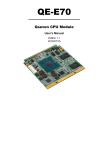
1
Q7A-551
Qseven Carrier Board
User’s Manual
A28400340
1
Chapter 1 Introduction
www.dfi.com
Copyright
FCC and DOC Statement on Class B
This publication contains information that is protected by copyright. No part of it may be reproduced in any form or by any means or used to make any transformation/adaptation without
the prior written permission from the copyright holders.
This equipment has been tested and found to comply with the limits for a Class B digital
device, pursuant to Part 15 of the FCC rules. These limits are designed to provide reasonable protection against harmful interference when the equipment is operated in a residential
installation. This equipment generates, uses and can radiate radio frequency energy and, if not
installed and used in accordance with the instruction manual, may cause harmful interference
to radio communications. However, there is no guarantee that interference will not occur in a
particular installation. If this equipment does cause harmful interference to radio or television
reception, which can be determined by turning the equipment off and on, the user is encouraged to try to correct the interference by one or more of the following measures:
This publication is provided for informational purposes only. The manufacturer makes no
representations or warranties with respect to the contents or use of this manual and specifically disclaims any express or implied warranties of merchantability or fitness for any particular
purpose. The user will assume the entire risk of the use or the results of the use of this document. Further, the manufacturer reserves the right to revise this publication and make changes
to its contents at any time, without obligation to notify any person or entity of such revisions
or changes.
•
•
•
Changes after the publication’s first release will be based on the product’s revision. The website
will always provide the most updated information.
•
Reorient or relocate the receiving antenna.
Increase the separation between the equipment and the receiver.
Connect the equipment into an outlet on a circuit different from that to which the receiver
is connected.
Consult the dealer or an experienced radio TV technician for help.
© 2015. All Rights Reserved.
Trademarks
Notice:
Product names or trademarks appearing in this manual are for identification purpose only and
are the properties of the respective owners.
1. The changes or modifications not expressly approved by the party responsible for compliance could void the user’s authority to operate the equipment.
2. Shielded interface cables must be used in order to comply with the emission limits.
2
Chapter 1 Introduction
www.dfi.com
Table of Contents
Digital I/O Connector .................................................................................. 18
Connect the EXT-KSDIO Module to the Digital I/O Connector
on the Carrier Board ............................................................................. 18
1W Audio Amplifier Connectors ................................................................... 19
FlexCAN Connector ..................................................................................... 19
Expansion Slots .......................................................................................... 20
LEDs .......................................................................................................... 20
RTC Battery ................................................................................................ 21
Power Switch.............................................................................................. 21
MXM Connector .......................................................................................... 22
Copyright........................................................................................................... ..2
Trademarks ........................................................................................................ 2
FCC and DOC Statement on Class B ..................................................... 2
About this Manual .......................................................................................... 4
Warranty
............................................................................................................ 4
Static Electricity Precautions...................................................................... 4
Safety Measures .............................................................................................. 4
About the Package ......................................................................................... 5
Chapter 1 - Introduction ............................................................................. 6
Specifications ................................................................................................ 6
Chapter 2 - Hardware Installation................................................ 7
Board Layout ................................................................................................. 7
Block Diagram ............................................................................................... 7
Mechanical Diagram .................................................................................... 8
Jumper Settings ........................................................................................... 9
Panel Power Select ....................................................................................... 9
COM 1/COM 2 RS232/422/485 Select ............................................................ 9
COM RS232/UART5 Select ........................................................................... 10
Touch Panel Power Select ........................................................................... 10
Dimming Mode Select ................................................................................. 11
LCD/Inverter Power Select .......................................................................... 11
Download Mode Select................................................................................ 12
Line-out/Mic-in Select ................................................................................. 12
Panel I/O Ports ........................................................................................... 13
USB ports................................................................................................... 13
USB Client Port ........................................................................................... 14
Serial (COM) Ports ...................................................................................... 14
RJ45 LAN Port ............................................................................................ 15
HDMI Port .................................................................................................. 15
Audio ......................................................................................................... 16
12~36V DC-in ........................................................................................... 16
I/O Connectors ........................................................................................... 17
LVDS LCD Panel Connector ......................................................................... 17
3
Chapter 1 Introduction
www.dfi.com
About this Manual
Static Electricity Precautions
An electronic file of this manual is included in the CD. To view the user’s manual in the CD, insert the CD into a CD-ROM drive. The autorun screen (Main Board Utility CD) will appear. Click
“User’s Manual” on the main menu.
It is quite easy to inadvertently damage your PC, system board, components or devices even
before installing them in your system unit. Static electrical discharge can damage computer
components without causing any signs of physical damage. You must take extra care in handling them to ensure against electrostatic build-up.
1. To prevent electrostatic build-up, leave the system board in its anti-static bag until you are
ready to install it.
Warranty
2. Wear an antistatic wrist strap.
1. Warranty does not cover damages or failures that arised from misuse of the product, inability to use the product, unauthorized replacement or alteration of components and product specifications.
3. Do all preparation work on a static-free surface.
4. Hold the device only by its edges. Be careful not to touch any of the components, contacts
or connections.
2. The warranty is void if the product has been subjected to physical abuse, improper installation, modification, accidents or unauthorized repair of the product.
5. Avoid touching the pins or contacts on all modules and connectors. Hold modules or connectors by their ends.
3. Unless otherwise instructed in this user’s manual, the user may not, under any circumstances, attempt to perform service, adjustments or repairs on the product, whether in or
out of warranty. It must be returned to the purchase point, factory or authorized service
agency for all such work.
Important:
Electrostatic discharge (ESD) can damage your processor, disk drive and other components. Perform the upgrade instruction procedures described at an ESD workstation only. If such a station is not available, you can provide some ESD protection by
wearing an antistatic wrist strap and attaching it to a metal part of the system chassis. If a wrist strap is unavailable, establish and maintain contact with the system
chassis throughout any procedures requiring ESD protection.
4. We will not be liable for any indirect, special, incidental or consequencial damages to the
product that has been modified or altered.
Safety Measures
To avoid damage to the system:
• Use the correct AC input voltage range.
To reduce the risk of electric shock:
• Unplug the power cord before removing the system chassis cover for installation or servicing. After installation or servicing, cover the system chassis before plugging the power
cord.
4
Chapter 1 Introduction
www.dfi.com
About the Package
The package contains the following items. If any of these items are missing or damaged,
please contact your dealer or sales representative for assistance.
•
•
•
•
One
One
One
One
Q7A-551 board
Power switch with cable
Speaker 1.5W with cable
QR (Quick Reference)
Optional Items
•
•
•
•
COM port cable
Power adapter (60W, 19V)
EXT-KSDIO module (8-bit DIO Daughter Board)
EXT-KSDIO cable
The board and accessories in the package may not come similar to the information listed
above. This may differ in accordance with the sales region or models in which it was sold. For
more information about the standard package in your region, please contact your dealer or
sales representative.
Before Using the System Board
Before using the system board, prepare basic system components.
If you are installing the system board in a new system, you will need at least the following
internal components.
•
Storage devices such as hard disk drive, CD-ROM, etc.
You will also need external system peripherals you intend to use which will normally include at
least a keyboard, a mouse and a video display monitor.
5
Chapter 1 Introduction
www.dfi.com
Chapter 1
Chapter 1 - Introduction
Specifications
Graphics
• Display ports
- 1 HDMI
- 2 24-bit single channel LVDS
Audio
• Supports I2S audio interface
• 2 1W audio amplifier connectors (left and right sides)
USB
• 2 USB 2.0 ports
• 1 USB Client port
Storage
• 1 mSATA via a Mini PCIe slot
• 1 SD card socket
Panel I/O Ports • 2 USB 2.0 ports
• 1 USB Client port
• 2 DB-9 serial ports
- 1 RS232/422/485
- 1 RS232/UART
• 1 RJ45 LAN port
• 1 HDMI port
• 1 Line-out/Mic-in jack
• 1 12~36V DC-in jack
I/O Connectors • 1 connector for an external RS232/422/485 serial port (2.0mm pitch)
•
•
•
•
1
2
1
1
LVDS LCD panel connector
1W audio amplifier connectors (left and right sides)
FlexCAN (Flexible Controller Area Network) connector
12-bit Digital I/O connector
Expansion Slots • 1 Mini PCIe slot
- supports PCIe and USB signals
- supports full size Mini PCIe card
• 1 SIM card socket
Temperature
• Operating: 0oC to 60oC
• Storage: -20oC to 85oC
Humidity
• 10% to 90%
Board to Board
Connector
• One MXM connector
Dimensions
• 190mm (7.48") x 102mm (4.02")
6
Chapter 1 Introduction
www.dfi.com
Chapter 2
Chapter 2 - Hardware Installation
Block Diagram
Board Layout
-
DC-in
12-36V
+
GLAN
COM
Power
Switch
1
RTC
Battery
AMP_L
2 1
2 1
3
1(JP12)
3
1(JP11)
LAN
USB 0-1
USB 2.0
USB Client 1
Mic-in/Line-out
Select (JP7)
2
HDMI
Mic-in/
Line-out
5
1
5
6
2
6
Audio Codec
Mic-in/Line-out
Select (JP8)
2
COM RS232/UART5 Select
(JP11)/(JP12)
Download Mode
Select (JP9)
Mini PCIe
3
Panel Power Select
Touch Panel Power Select
LCD/Inverter Power Select
Dimming Mode Select
(JP2)
(JP3)
5
6
1
2
5
6
1
2
(JP5)
(JP2)
(JP3)
(JP5)
(JP10)
1
40
39
MXM
10
9
mSATA
1
2
2
1
IT8518E
FlexCAN
COM 1 RS232/422/485
Select (JP4)
6 5
2 1
SD
1
USB 2x
ITE
MCS7840CV
6 5
2
LVDS LCD Panel
1
Digital I/O
1
(JP10)
2
1
13
14
Mini PCIe (mSATA)
SIM
AMP_R
10
9
2
1
COM 1
USB Client
SD LED
PCIe
HDA
USB
Mini PCIe 1x
SATA 2.0
SPI
USB 2.0
USB Client
LVDS
Q7
MXM
Connector
HDMI
Digital I/O
Power LED
COM 2 RS232/422/485
Select (JP6)
COM 3x
2 1
COM 2
CAN
FlexCAN
SDIO
7
Chapter 2 Hardware Installation
www.dfi.com
Chapter 2
185.00
136.21
117.51
104.01
73.70
28.88
5.50
Mechanical Diagram
102.03
97.00
96.07
90.71
75.71
59.52
41.71
39.21
29.94
26.71
24.00
17.00
14.98
190.01
173.65
145.49
119.14
101.50
87.40
75.00
58.50
45.00
50.01
0.00
5.50
0.00
8
Chapter 2 Hardware Installation
www.dfi.com
Chapter 2
Jumper Settings
COM 1/COM 2 RS232/422/485 Select
Panel Power Select
COM 1:
RS232/422/485
9
COM 1
JP4
JP6
21
JP2
5 3 1
5 3 1
5 3 1
6 4 2
6 4 2
3-4 On:+5V_standby
6 4 2
5-6 On: +3V_standby
(default)
COM 2:
RS232/422/485
COM 2
1-2 On: +12V
JP4 (for COM 1) and JP6 (for COM 2) are used to configure the COM ports to RS232, RS422
(Full Duplex) or RS485. The pin functions of COM ports will vary according to jumpers’ setting.
JP4 (for COM 1)/ JP6 (for COM 2)
JP2 is used to select the power supplied with the LCD panel.
6
4
2
Important:
Before powering-on the system, make sure that the power settings of JP2 match the
LCD panel’s specification. Selecting the incorrect voltage will seriously damage the
LCD panel.
5
3
1
1-2 On: RS232
(default)
5
3
1
6
4
2
3-4 On: RS422
Full Duplex
6
4
2
5
3
1
5-6 On: RS485
N.C.
N.C.
N.C.
N.C.
6789
N.C.
N.C.
N.C.
N.C.
6789
1 2345
DSRRTSCTSRI-
6789
1 2345
DATA+
DATAN.C.
N.C.
N.C.
1 2345
RXD+
RXDTXD+
TXDN.C.
DCDRD
TD
DTRGND
COM 2
RS232
RS422
Full Duplex
RS485
9
Chapter 2 Hardware Installation
www.dfi.com
Chapter 2
COM RS232/UART5 Select
Touch Panel Power Select
COM
JP12
JP11
3 2 1
1-2 On:
RS232 (default)
3 2 1
JP3
2-3 On: UART5
3 2 1
1-2 On:
+3V_standby
3 2 1
2-3 On: +5V_standby
(default)
JP3 controls the power level of the touch panel IC.
JP11 and JP12 are used to configure the COM port to RS232 (default) or UART5.
Important:
You need to set JP11 and JP12 simultaneously.
10
Chapter 2 Hardware Installation
www.dfi.com
Chapter 2
Dimming Mode Select
LCD/Inverter Power Select
JP5
JP10
3 2 1
1-2 On:
PWM Mode (default)
5 3 1
5 3 1
5 3 1
6 4 2
6 4 2
3-4 On:+5V_standby
(default)
6 4 2
5-6 On: +3V_standby
3 2 1
2-3 On:
Voltage Mode
1-2 On: +12V
JP10 allows you to select the mode for the lightness control of the LVDS panel.
JP5 is used to select the power level of the LCD/inverter power connector.
Important:
You need to refer to your panel’s user guide to determine the type of mode (PWM or
Voltage) most appropriate for your panel.
11
Chapter 2 Hardware Installation
www.dfi.com
Chapter 2
Download Mode Select
Line-out/Mic-in Select
JP7 1-2, 3-4, 5-6 On:
Line-out
3 2 1
1 3 5
JP8 1-2, 3-4, 5-6 On:
Mic-in (default)
2 4 6
JP7 JP8
1-2 On: Serial
Download Mode
JP9
3 2 1
2-3 On: Normal Boot
(default)
JP9 allows you to select the download mode of serial port to update the firmware and OS.
JP7 and JP8 allow you to select the audio function. When pins 1-2, 3-4, and 5-6 are set to On,
JP7 is applied for the Line-out function and JP8 is used for the Mic-in function.
12
Chapter 2 Hardware Installation
www.dfi.com
Chapter 2
Panel I/O Ports
COM
DC-in
USB Ports
LAN
USB
0-1
USB 2.0
USB 1
USB 0
Line-out/Mic-in
HDMI
-
USB
Client
+
The USB device allows data exchange between your computer and a wide range of simultaneously accessible external Plug and Play peripherals. The system board is equipped with two
onboard USB 2.0 ports (USB 0-1).
COM 2
The panel I/O ports consist of the following:
•
•
•
•
•
•
•
2
1
2
1
1
1
1
USB 2.0 ports
USB Client port
Serial COM ports
RJ45 LAN port
HDMI port
Line-out/Mic-in jack
12~36V DC-in jcak
13
Chapter 2 Hardware Installation
www.dfi.com
Chapter 2
Serial (COM) Ports
DCDRD
TD
DTRGND
USB Client Port
1 2 3 4 5
USB Client
COM
6 7 89
DSRRTSCTSRI-
COM:
RS232 or UART5
9
COM 1:
RS232/422/485
2 1
The shape of the mini USB port is smaller than the standard one and is a device operating as
a client port.
COM 2:
RS232/422/485
The system board is equipped with two onboard serial COM ports (COM and COM 2). It is also
equipped with a 9-pin connector for connecting an external serial COM port (COM 1). COM is
fixed at RS232 or UART5 via JP11’s and JP12’s setting at the same time. COM port 1 and COM
port 2 will vary according to JP4’s (for COM 1) and JP6’s (for COM 2) setting respectively.
The serial COM port is RS232 asynchronous communication port with 16C550A-compatible
UARTs that can be used with modems, serial printers, remote display terminals, and other serial devices. To connect COM 1, please refer to the following description. The serial port may
be mounted on a card-edge bracket. Install the card-edge bracket to an available slot at the
rear of the system chassis then insert the cable connector to the 9-pin connector. Make sure
the colored stripe on the ribbon cable is aligned with pin 1 of the connector.
Important:
You need to set JP11 and JP12 simultaneously.
14
Chapter 2 Hardware Installation
www.dfi.com
Chapter 2
RJ45 LAN Port
HDMI Port
LAN
HDMI
The onboard RJ45 LAN port allows the system board to connect to a local area network by
means of a network hub.
The HDMI port which carries both digital audio and video signals is used to connect a LCD
monitor or digital TV that has the HDMI port.
15
Chapter 2 Hardware Installation
www.dfi.com
Chapter 2
Audio
12~36V DC-in
Line-out/Mic-in
DC-in
-
The system board is equipped with 1 audio jack to operate as a line-out jack or a mic-in jack.
A jack is a one-hole connecting interface for inserting a plug. Being a line-out jack, this jack
is used to connect a headphone or external speakers. Being a mic-in jack, this jack is used to
connect to the center and subwoofer speakers of the audio system.
+
This jack provides maximum of 60W power and is considered a low power solution. Connect
a DC power cord to this jack. Use a power adapter within 12~36V DC output voltage. Using a
voltage out of the range 12~36V may fail to boot the system or cause damage to the system
board.
16
Chapter 2 Hardware Installation
www.dfi.com
Chapter 2
I/O Connectors
The table below illustrates the pin functions of the LVDS LCD Panel connector:
LVDS LCD Panel Connector
Pins
Function
Pins
Function
1
GND
2
GND
3
LVDS1_Out3+
4
LVDS0_Out3+
5
LVDS1_Out3-
6
LVDS0_Out3-
7
GND
8
GND
9
LVDS1_Out2+
10
LVDS0_Out2+
11
LVDS1_Out2-
12
LVDS0_Out2-
13
GND
14
GND
15
LVDS1_Out1+
16
LVDS0_Out1+
17
LVDS1_Out1-
18
LVDS0_Out1-
19
GND
20
GND
21
LVDS1_Out0+
22
LVDS0_Out0+
23
LVDS1_Out0-
24
LVDS0_Out0-
25
GND
26
GND
27
LVDS1_CLK+
28
LVDS0_CLK+
29
LVDS1_CLK-
30
LVDS0_CLK-
31
GND
32
GND
Jumper Settings
33
TP_INT
34
TP_SCL
Refer to the “Jumper Settings” section in this chapter for settings relevant to the LCD panel.
35
TP_VDD
36
TP_SDA
37
Backlight Power
38
Dimming
39
Backlight Power
40
Panel Power
40
2
39
1
LVDS LCD Panel
The system board allows you to connect a LCD Display Panel by means of the LVDS LCD panel
connector transmitting video signals and power from the system board to the LCD Display
Panel.
Refer to the right side for the pin functions of the connector.
Note:
DFI board's LVDS connector: Hirose DF13-40DP-1.25V(91)/40P/1.25mm; cable side
connector: Hirose DF13-40DS-1.25C.
17
Chapter 2 Hardware Installation
www.dfi.com
Chapter 2
Digital I/O Connector
Connect the EXT-KSDIO Module to the Digital I/O Connector on the Carrier Board
The EXT-KSDIO module (8-bit digital I/O daughter board) is designed to connected to a digital
I/O connector on the Q7A-551 carrier board via an EXT-KSDIO cable for extending 8-bit GPIO
7-pole terminal blocks at the I/O ports of the system unit.
Digital I/O
13
14
1
2
EXT-KSDIO
(Top View)
EXT-KSDIO
(Bottom View)
GPIO
External Digital
I/O Connector
EXT-KSDIO
The 12-bit Digital I/O connector provides powering-on function to external devices that are
connected to the connector. The pin functions of the digital I/O connector are listed below:
EXT-KSDIO
cable
Digital I/O Connector
Digital I/O connector
Pins
Function
Pins
Function
1
DIO_OUT-1
8
DIO_IN-4
2
DIO_IN-1
9
DIO_OUT-5
3
DIO_OUT-2
10
DIO_IN-5
4
DIO_IN-2
11
DIO_OUT-6
5
DIO_OUT-3
12
DIO_IN-6
6
DIO_IN-3
13
DCDC_5V_BB
7
DIO_OUT-4
14
GND
Q7A-551
Important:
When connecting the EXT-KSDIO module to a digital I/O connector on the Q7A-551
carrier board, make sure the white dot on the EXT-KSDIO connector is aligned with
pin 1 of the digital I/O connector on the carrier board. If the cause of damages due to
personal incorrect installation, DFI will not be responsible for any damages.
18
Chapter 2 Hardware Installation
www.dfi.com
Chapter 2
1W Audio Amplifier Connectors
FlexCAN Connector
AMP_L
AMP_R
2
1
AOUT_L+
AOUT_L2
FlexCAN
1
9
AOUT_R+
AOUT_R-
N.C
N.C
N.C
CAN_LO
N.C
N.C
GND
CAN_HI
N.C
2 1
The amplify right/left connectors which have amplifying feature are used to connect external
speakers.
The CAN controller performs communication in accordance with the BOSCH CAN Protocol Version 2.0B Active1 (standard format and extended format). The bit rate can be programmed to
a maximum of 1Mbit/s. To connect the CAN controller module to the FlexCAN connector, it is
necessary to add transceiver hardware.
When communicating in a CAN network, individual message objects are configured. The message objects and the identifier masks for the receive filter for the received messages are
stored in the message RAM.
Controller Area Network is a message based protocol designed specifically for automotive applications but now is also used in other areas such as industrial automation and medical equipment.
19
Chapter 2 Hardware Installation
www.dfi.com
Chapter 2
Expansion Slots
LEDs
SIM Card Socket
Mini PCIe
(supports PCIe and USB signals)
Mini PCIe
(Supports mSATA signal)
SD LED
Power LED
SD Card Socket
Mini PCIe Slot
SD LED
The Mini PCIe socket is used to install a Mini PCIe card. Mini PCIe card is a small form factor
PCI card with the same signal protocol, electrical definitions, and configuration definitions as
the conventional PCI.
The SD LED will light when the SDIO card is inserted into the SD/MMC socket.
SIM Card Socket
The power LED indicates that there is power on the system board. Power-off the PC and then
unplug the power cord prior to installing any devices. Failure to do so will cause severe damage to the system board and components.
Power LED
The SIM slot on the system board is used to insert a SIM card.
SD Card Socket
This expansion port is used to insert a Secure Digital Input/Output (SDIO) device. Aside from
storing data files, an SDIO card is also capable of storing powerful software applications.
20
Chapter 2 Hardware Installation
www.dfi.com
Chapter 2
RTC Battery
2
1
Power Switch
RTC
Battery
2
1
Power
Switch
Power_Enable
GND
+3.3V
GND
Power Switch
The power switch is used to power on or power off the system.
Battery
Connect to the battery connector
The RTC Battery powers the real-time clock and CMOS memory. It is an auxiliary source of
power when the main power is shut off.
Safety Measures
• Danger of explosion if battery incorrectly replaced.
• Replace only with the same or equivalent type recommend by the manufacturer.
• Dispose of used batteries according to local ordinance.
21
Chapter 2 Hardware Installation
www.dfi.com
Chapter 2
MXM Connector
Pin
1
3
5
7
9
11
13
15
17
19
21
23
25
27
29
31
33
35
37
39
41
43
45
47
49
51
53
55
57
59
61
63
65
67
69
71
73
75
77
79
81
83
85
87
89
91
93
95
97
99
MXM
Connector
The MXM connector is used to interface the carrier board with a Qseven board. Refer to the
table in the following pages for the pin functions of the MXM connector.
Signal
GND
GBE_MDI3GBE_MDI3+
GBE_LINK100#
GBE_MDI1GBE_MDI1+
GBE_LINK#
WAKE#
SUS_STAT#
SLP_BTN#
GND
GND
BATLOW#
SATA0_TX+
SATA0_TXSATA0_ACT#
SATA0_RX+
SATA0_RXGND
BIOS_DISABLE#/BOOT_ALT#
SDIO_CD#
SDIO_CMD
SDIO_PWR#
SDIO_DAT0
SDIO_DAT2
SDIO_DAT4
SDIO_DAT6
GND
I2S_TXFS
I2S_CLK
I2S_TXC
I2S_RXD
I2S_TXD
GND
USB_2_3_OC#
USB_P3USB_P3+
USB_CC
USB_P1USB_P1+
GND
LVDS_A0+
Pin
2
4
6
8
10
12
14
16
18
20
22
24
26
28
30
32
34
36
38
40
42
44
46
48
50
52
54
56
58
60
62
64
66
68
70
72
74
76
78
80
82
84
86
88
90
92
94
96
98
100
Signal
GND
GBE_MDI2GBE_MDI2+
GBE_LINK1000#
GBE_MDI0GBE_MDI0+
GBE_ACT#
SUS_S5#
SUS_S3#
PWRBTN#
LID_BTN#
GND
PWGIN
RSTBTN#
GND
GND
SDIO_CLK
SDIO_LED
SDIO_WP
SDIO_DAT1
SDIO_DAT3
SDIO_DAT5
SDIO_DAT7
RSVD
GND
SMB_CLK
SMB_DAT
SMB_ALERT#
I2C_CLK
I2C_DAT
WDTRIG#
WDOUT
GND
USB_4_5_OC#
USB_P4USB_P4+
USB_0_1_OC#
USB_P2USB_P2+
USB_ID
USB_P0USB_P0+
GND
LVDS_B0+
22
Chapter 2 Hardware Installation
www.dfi.com
Chapter 2
Pin
101
103
105
107
109
111
113
115
117
119
121
123
125
127
129
131
133
135
137
139
141
143
145
147
149
151
153
155
157
159
161
163
165
167
169
171
173
175
177
179
181
183
185
187
189
191
193
195
197
199
Signal
LVDS_A0LVDS_A1+
LVDS_A1LVDS_A2+
LVDS_A2LVDS_PPEN
LVDS_A3+
LVDS_A3GND
LVDS_A_CLK+
LVDS_A_CLKLVDS_BLT_CTRL/GP_PWM_OUT0
LVDS_DID_DAT/GP_I2C_DAT
LVDS_DID_CLK/GP_I2C_CLK
CAN0_TX
TMDS_CLK+
TMDS_CLKGND
TMDS_LANE1+
TMDS_LANE1GND
TMDS_LANE0+
TMDS_LANE0GND
TMDS_LANE2+
TMDS_LANE2HDMI_HPD#
PCIE_CLK_REF+
PCIE_CLK_REFGND
GND
UART_TXD
UART_RXD
PCIE0_TX+
PCIE0_TXGND
VCC_RTC
GND
SPI_MOS1
Pin
102
104
106
108
110
112
114
116
118
120
122
124
126
128
130
132
134
136
138
140
142
144
146
148
150
152
154
156
158
160
162
164
166
168
170
172
174
176
178
180
182
184
186
188
190
192
194
196
198
200
Signal
LVDS_B0LVDS_B1+
LVDS_B1LVDS_B2+
LVDS_B2LVDS_BLEN
LVDS_B3+
LVDS_B3GND
LVDS_B_CLK+
LVDS_B_CLKRSVD
LVDS_BLC_DAT
LVDS_BLC_CLK
CAN0_RX
Pin
201
203
205
207
209
211
213
215
217
219
221
223
225
227
229
Signal
SPI_MOS0
SPI_SCK
5V_SB
MFG_NC0
MFG_NC1
VCC (+5V)
VCC (+5V)
VCC (+5V)
VCC (+5V)
VCC (+5V)
VCC (+5V)
VCC (+5V)
VCC (+5V)
VCC (+5V)
VCC (+5V)
Pin
202
204
206
208
210
212
214
216
218
220
222
224
226
228
230
Signal
MFG_NC4
5V_SB
MFG_NC2
MFG_NC3
VCC (+5V)
VCC (+5V)
VCC (+5V)
VCC (+5V)
VCC (+5V)
VCC (+5V)
VCC (+5V)
VCC (+5V)
VCC (+5V)
VCC (+5V)
GND
GND
GND
HDMI_CTRL_DAT
HDMI_CTRL_CLK
PCIE_WAKE#
PCIE_RST#
GND
GND
UART_RTS
UART_CTS
PCIE0_RX+
PCIE0_RXGND
GND
SPI_CS0#
23
Chapter 2 Hardware Installation
www.dfi.com