1
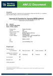
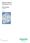
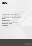
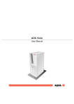
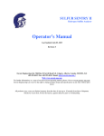
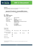
EtherNet/IP
Adapter
22-COMM-E
FRN 1.xxx
User Manual
Chapter 6
Using Explicit Messaging
Chapter 6 provides information and examples that explain how to use
Explicit Messaging to configure and monitor the EtherNet/IP adapter
installed and connected to the PowerFlex 40 drive.
Topic
About Explicit Messaging
Formatting Explicit Messages
Performing Explicit Messages
!
!
Page
6-1
6-2
6-4
Topic
About the Example Explicit Messages
Example Get Attribute Single Message
Example Set Attribute Single Message
Page
6-5
6-6
6-8
ATTENTION: Risk of injury or equipment damage exists. The
examples in this publication are intended solely for purposes of
example. There are many variables and requirements with any
application. Rockwell Automation, Inc. does not assume responsibility
or liability (to include intellectual property liability) for actual use of
the examples shown in this publication.
ATTENTION: Risk of equipment damage exists. If Explicit Messages
are programmed to write parameter data to Non-Volatile Storage (NVS)
frequently, the NVS will quickly exceed its life cycle and cause the
drive to malfunction. Do not create a program that frequently uses
Explicit Messages to write parameter data to NVS.
Refer to Chapter 5 for information about the I/O image, using Logic
Command/Status and Reference/Feedback.
About Explicit Messaging
Explicit Messaging is used to transfer data that does not require
continuous updates. With Explicit Messaging, you can configure and
monitor a slave device’s parameters on the EtherNet/IP network.
6-2
Using Explicit Messaging
Formatting Explicit Messages
Explicit Messages for the ControlLogix Controller
ControlLogix scanners and bridges accommodate both downloading
Explicit Message Requests and uploading Explicit Message Responses.
The scanner or bridge module can accommodate one request or response
for each transaction block. Each transaction block must be formatted as
shown in Figure 6.1.
Figure 6.1 ControlLogix Message Format in RSLogix 5000
11
➓
➊
➋
➌
➎
➍
➏
➐
➑
➒
Refer to page 6-3 for a description of the data that is required in each box
(1 – 11).
TIP: To display the Message Configuration dialog box in RSLogix
5000, add a message instruction (MSG), create a new tag for the
message (properties: Base tag type, MESSAGE data type, controller
scope), and click the blue box inside the message.
Using Explicit Messaging
6-3
ControlLogix Message Requests and Responses
Box Description
➊ Message Type
The message type must be CIP Generic.
➋ Service Type
The service type indicates the service (for example, Get Attribute Single or Set
Attribute Single) that you want to perform. Available services depend on the class
and instance that you are using. Refer to Appendix C, EtherNet/IP Objects.
➌ Service Code
The service code is the code for the requested EtherNet/IP service. This value
changes based on the Service Type that has been selected. In most cases, this is
a read-only box. If you select “Custom” in the Service Type box, then you need to
specify a service code in this box (for example, 4B for a Get Attributes Scattered
service or 4C for a Set Attributes Scattered service).
➍ Class
The class is an EtherNet/IP class. Refer to Appendix C, EtherNet/IP Objects, for
available classes.
➎ Instance
The instance is an instance (or object) of an EtherNet/IP class. Refer to
Appendix C, EtherNet/IP Objects, for available instances for each class.
➏ Attribute
The attribute is a class or instance attribute. Refer to Appendix C, EtherNet/IP
Objects, for available attributes for each class or instance.
➐ Source Element
This box contains the name of the tag for any service data to be sent from the
scanner or bridge to the adapter and drive.
➑ Source Length
This box contains the number of bytes of service data to be sent in the message.
➒ Destination
This box contains the name of the tag that will receive service response data from
the adapter and drive.
➓ Path
The path is the route that the message will follow.
11
Tip: Click Browse to find the path or type in the name of an adapter that you
previously mapped.
Name
The name for the message.
6-4
Using Explicit Messaging
Performing Explicit Messages
There are five basic events in the Explicit Messaging process. The details
of each step will vary depending on the controller. Refer to the
documentation for your controller.
Figure 6.2 Explicit Message Process
➊
➎
Complete Explicit
Message
➍
Retreive Explicit
Message Respnse
Set up and send Explicit
Message Request
➋
➌
Event
1. You format the required data and set up the ladder logic program to
send an Explicit Message request to the scanner or bridge module
(download).
2. The scanner or bridge module transmits the Explicit Message
Request to the slave device over the Ethernet network.
3. The slave device transmits the Explicit Message Response back to
the scanner. The data is stored in the scanner buffer.
4. The controller retrieves the Explicit Message Response from the
scanner’s buffer (upload).
5. The Explicit Message is complete.
Using Explicit Messaging
6-5
About the Example Explicit Messages
These examples show how to format and execute the following types of
Explicit Messages using a ControlLogix controller:
• Get Attribute Single
• Set Attribute Single
Message Formats
When formatting an example message, refer to Formatting Explicit
Messages in this chapter for an explanation of the content of each box.
Also, to format and execute these example messages, you need the
Controller tags displayed in Figure 6.3.
Figure 6.3 Controller Tags for Explicit Messages
Ladder Logic Rungs
The ladder logic rungs for the examples in this chapter can be appended
after rung 12 in the ladder logic program (Figure 5.5) in Chapter 5,
Using I/O Messaging.
Source and Destination Data
The example values for the source and destination data that appear in
this chapter may vary in your application.
6-6
Using Explicit Messaging
Example Get Attribute Single Message
A Get Attribute Single message reads a single attribute value. In this
example, we read the value of a parameter in a PowerFlex 40 drive.
Example Message Format
Figure 6.4 Message Format for a Get Attribute Single Message
The following table identifies key settings for the message format:
Configuration
Service Type (1)
Service Code (1)
Class
Instance
Attribute
Destination
(1)
Value
Get Attribute Single
e (Hex.)
f (Hex.)
39 (Dec.)
1 (Hex.)
ParameterReadValue
Description
Read parameter data
Get_Attribute_Single
DSI Parameter Object
Parameter 39 - [Accel Time 1]
Parameter Value
Controller tag for response data
Refer to . . .
C-27
C-12
C-24
C-24
C-25
—
The default setting for Service Type is “Custom,” which enables you to enter a Service
Code that is not available from the Service Type pulldown menu. When you select a
Service Type other than “Custom” from the pulldown menu, an appropriate Hex. value
is automatically assigned to the Service Code box which grays out (unavailable).
Using Explicit Messaging
6-7
Example Ladder Logic Rung
Figure 6.5 Example Get Attribute Single Message
([SOLFLW0HVVDJLQJ([DPSOH
([SOLFLW0HVVDJLQJ([DPSO
5HDGLQJDVLQJOHSDUDPHWHU*HW$WWULEXWH6LQJOHFRPPDQG
3HUIRUP3DUDPHWHU5HDG
7\SH&,3*HQHULF
0HVVDJH&RQWURO
06*
3DUDPHWHU5HDG0HVVDJH (1
'1
(5
Example Destination Data
In this example, the Get Attribute Single message reads Parameter 39 [Accel Time 1] in the PowerFlex 40 drive and returns its value to the
destination tag named ParameterReadValue.
Figure 6.6 Example Destination Data from a Get Attribute Single Message
The acceleration time is 10.0 seconds.
6-8
Using Explicit Messaging
Example Set Attribute Single Message
A Set Attribute Single message writes a value for a single attribute. In
this example, we write the value of a parameter in a PowerFlex 40 drive.
Example Message Format
Figure 6.7 Message Format for a Set Attribute Single Message
The following table identifies key settings for the data format:
Configuration
Service Type (1)
Service Code (1)
Class
Instance
Attribute
Source Element
Source Length
(1)
Value
Set Attribute Single
10 (Hex.)
f (Hex.)
39 (Dec.)
1 (Hex.)
ParameterWriteValue
2 bytes
Description
Write parameter data
Set_Attribute_Single
DSI Parameter Object
Parameter 39 - [Accel Time 1]
Parameter Value
Controller tag for write data
One 16-bit word of data is sent
Refer to . . .
C-27
C-12
C-24
C-24
C-25
—
—
The default setting for Service Type is “Custom,” which enables you to enter a Service
Code that is not available from the Service Type pulldown menu. When you select a
Service Type other than “Custom” from the pulldown menu, an appropriate Hex. value
is automatically assigned to the Service Code box which grays out (unavailable).
Using Explicit Messaging
6-9
Example Ladder Logic Rung
Figure 6.8 Example Set Attribute Single Message
([SOLFLW0HVVDJLQJ([DPSOH
:ULWLQJDVLQJOHSDUDPHWHU6HW$WWULEXWH6LQJOHFRPPDQG
3HUIRUP3DUDPHWHU:ULWH
7\SH&,3*HQHULF
0HVVDJH&RQWURO
06*
3DUDPHWHU:ULWH0HVVDJH (1
'1
(5
Example Source Data
In this example, the Set Attribute Single message writes 100, the value in
the source tag named ParameterWriteValue, to Parameter 39 - [Accel
Time 1] in the PowerFlex 40 drive.
Figure 6.9 Example Source Data from a Set Attribute Single Message
10.0 seconds is written to the parameter.
6-10
Notes:
Using Explicit Messaging
Appendix C
EtherNet/IP Objects
Appendix C provides information about the EtherNet/IP objects that can
be accessed using Explicit Messages. For information on the format of
Explicit Messages and example ladder logic programs, refer to
Chapter 6, Using Explicit Messaging.
Object
Identity Object
Assembly Object
Register Object
Parameter Object
Parameter Group Object
PCCC Object
Class Code
Hex. Dec.
0x01 1
0x04 4
0x07 7
0x0F 15
0x10 16
0x67 103
Page
C-2
C-4
C-6
C-9
C-13
C-15
Object
DPI Device Object
DPI Parameter Object
DPI Fault Object
DPI Diagnostic Object
TCP/IP Interface Object
Ethernet Link Object
Class Code
Hex. Dec.
0x92 146
0x93 147
0x97 151
0x99 153
0xF5 245
0xF6 246
Page
C-21
C-24
C-28
C-30
C-32
C-34
TIP: Refer to the EtherNet/IP specification for more information about
EtherNet/IP objects. Information about the EtherNet/IP specification is
available on the ODVA web site (http://www.odva.org).
Supported Data Types Data Type
BYTE
WORD
DWORD
LWORD
SINT
USINT
INT
UINT
DINT
UDINT
BOOL
BOOL[n]
STRING[n]
SHORT_STRING
STRUCT
CONTAINER
TCHAR
REAL
Description
8-bit unsigned integer
16-bit unsigned integer
32-bit unsigned integer
64-bit unsigned integer
8-bit signed integer
8-bit unsigned integer
16-bit signed integer
16-bit unsigned integer
32-bit signed integer
32-bit unsigned integer
8-bit value -- low bit is true or false
Array of n bits
Array of n characters
1-byte length indicator + that many characters
Structure name only - no size in addition to elements
32-bit parameter value - sign extended if necessary
8 or 16-bit character
32-bit floating point
C-2
EtherNet/IP Objects
Identity Object
Class Code
Hexadecimal
0x01
Decimal
1
Instances (Single-Drive Mode)
The number of instances is fixed at three and is as shown below:
Instance
0
1
2
3
Description
Class
Host drive
22-COMM-E
22-SCM-232 or 22-HIM-* (when present)
Instances (Multi-Drive Mode)
The number of instances is fixed at one and is as shown below:
Instance
0
1
Description
Class
22-COMM-E
Class Attributes
Attribute
ID
1
2
6
Access
Rule
Get
Get
Get
7
Get
Name
Revision
Max Instance
Max ID Number
of Class
Attributes
Max ID Number
of Instance
Attributes
Data Type
UINT
UINT
UINT
Description
1
Total number of instances
7
UINT
100
EtherNet/IP Objects
C-3
Identity Object (Continued)
Instance Attributes
Attribute
ID
1
2
3
Acces
s Rule
Get
Get
Get
4
Get
5
Get
6
7
Get
Get
9
Get
100
Get
Name
Vendor ID
Device Type
Product Code
Data Type
UINT
UINT
UINT
Revision:
Major
Minor
Status
STRUCT of:
USINT
USINT
WORD
Description
1 = Allen-Bradley
127
Number identifying product
name and rating
Serial Number UDINT
Product Name SHORT_
STRING
Configuration UINT
Consistency
Value
NVS Info
STRUCT of:
UDINT
SHORT_STRING
Value varies
Value varies
Bit 0 = Owned
Bit 2 = Configured
Bit 10 = Recoverable fault
Bit 11 = Unrecoverable fault
Unique 32-bit number
Product name and rating
CRC or checksum
representing the configuration
of the product
First NVS instance
Sub-assembly name
Services
Service Code
0x01
0x05
0x0E
Implemented for:
Class
Instance
Yes
Yes
No
Yes
Yes
Yes
Service Name
Get_Attributes_All
Reset
Get_Attribute_Single
C-4
EtherNet/IP Objects
Assembly Object
Class Code
Hexadecimal
0x04
Decimal
4
Instances
Instance
1
2
Description
All I/O data being read from the DSI drives (read-only)
All I/O data written to the DSI drives (read/write)
Class Attributes
Attribute
ID
1
2
100
Access Rule
Get
Get
Set
Name
Revision
Max Instance
Control
Timeout
Data Type
UINT
UINT
UINT
Description
2
2
Control timeout in seconds
Name
Number of
Members
Member List
Data Type
UINT
Description
1
Instance Attributes
Attribute
ID
Access Rule
1
Get
2
3
4
(1)
Get
Conditional (1) Data
Get
Size
ARRAY of
STRUCT:
UINT
UINT
Packed
EPATH
Array of Bits
UINT
Size of member data
Size of member path
Member path
Data to be transferred
Size of assembly data in bits
For instance 1, access rule for the data attribute is Get. For instance 2, it is Get/Set.
Important: Setting an Assembly object attribute can be done only when
the Control Timeout (class attribute 100) has been set to a
non-zero value.
EtherNet/IP Objects
Assembly Object (Continued)
Services
Service Code
0x0E
0x10
Implemented for:
Class
Instance
Yes
Yes
Yes
Yes
Service Name
Get_Attribute_Single
Set_Attribute_Single
C-5
C-6
EtherNet/IP Objects
Register Object
Class Code
Hexadecimal
0x07
Decimal
7
Instances
Instance Description
1
2
3
4
5
6
7
8
9
10
11
12
13
14
15
16
17
18
19
20
21
22
23
24
25
26
Logic Command and Reference for all drives
Logic Status and Feedback for all drives
Logic Command and Reference for Drive 0
Logic Status and Feedback for Drive 0
Logic Command and Reference for Drive 1
Logic Status and Feedback for Drive 1
Logic Command and Reference for Drive 2
Logic Status and Feedback for Drive 2
Logic Command and Reference for Drive 3
Logic Status and Feedback for Drive 3
Logic Command and Reference for Drive 4
Logic Status and Feedback for Drive 4
Logic Command for all drives — mask-and-match register (2)
Logic Command for Drive 0 — mask-and-match register (2)
Logic Command for Drive 1 — mask-and-match register (2)
Logic Command for Drive 2 — mask-and-match register (2)
Logic Command for Drive 3 — mask-and-match register (2)
Logic Command for Drive 4 — mask-and-match register (2)
Logic Command for Drive 0
Logic Status for Drive 0
Reference for Drive 0
Feedback for Drive 0
Logic Command for Drive 1
Logic Status for Drive 1
Reference for Drive 1
Feedback for Drive 1
Input/
Output
Out
In
Out
In
Out
In
Out
In
Out
In
Out
In
Out
Out
Out
Out
Out
Out
Out
In
Out
In
Out
In
Out
In
Size
(in bits)
Varies (1)
Varies (1)
32
32
32
32
32
32
32
32
32
32
Varies (1)
32
32
32
32
32
16
16
16
16
16
16
16
16
(1)
The size for this Register Object instance is 32 bits per drive. For example, if the adapter is
operating in Multi-Drive mode, and is configured with Drives 0 through 4, then the size is 160
bits.
(2)
The structure for this Register Object instance is a Mask word followed by a Command word
for each drive. The Logic Command for each drive is set to the value of the second word of
the data where there are ones in the first word of the data.
Logic Command = (Logic Command and not Mask word) or (Command word and Mask word)
EtherNet/IP Objects
C-7
Register Object (Continued)
Instances (Continued)
Input/
Output
Out
In
Out
In
Out
In
Out
In
Out
In
Out
In
Instance Description
27
28
29
30
31
32
33
34
35
36
37
38
Logic Command for Drive 2
Logic Status for Drive 2
Reference for Drive 2
Feedback for Drive 2
Logic Command for Drive 3
Logic Status for Drive 3
Reference for Drive 3
Feedback for Drive 3
Logic Command for Drive 4
Logic Status for Drive 4
Reference for Drive 4
Feedback for Drive 4
Size
(in bits)
16
16
16
16
16
16
16
16
16
16
16
16
Class Attributes
Attribute
ID
1
2
3
100
Access
Rule
Get
Get
Get
Set
Name
Revision
Max Instance
Number of Instances
Control Timeout
Data Type
UINT
UINT
UINT
UINT
Description
1
38
38
Control timeout in seconds
C-8
EtherNet/IP Objects
Register Object (Continued)
Instance Attributes
Attribute
ID
Access Rule
1
Get
Name
Bad Flag
2
Get
Direction
3
4
Get
Size
Conditional (1) Data
(1)
Data Type Description
BOOL
If set to 1, then attribute 4
contains invalid, bad or otherwise
corrupt data.
0 = good
1 = bad
BOOL
Direction of data transfer
0 = Input (Drive to EtherNet/IP)
1 = Output (EtherNet/IP to Drive)
UINT
Size of register data in bits
ARRAY of Data to be transferred
BITS
The access rule of Set is optional if attribute 2, Direction = 1. If Direction = 0, the
access rule is Get.
Important: Setting a Register object attribute can be done only when
the Control Timeout (class attribute 100) has been set to a
non-zero value.
Service Code
0x0E
0x10
Implemented for:
Class
Instance
Yes
Yes
Yes
Yes
Service Name
Get_Attribute_Single
Set_Attribute_Single
EtherNet/IP Objects
C-9
Parameter Object
Class Code Hexadecimal
0x0F
Decimal
15
Instances (Single-Drive Mode)
The number of instances is as shown below:
Instance
0
1
R
n
n+1
R
n+m
(1)
(2)
Description
Class
Drive Parameter 1
R
Drive Parameter n (1)
Adapter Parameter 1
R
Adapter Parameter m (2)
n represents the number of parameters in the drive.
m represents the number of parameters in the adapter.
Instances (Multi-Drive Mode)
The number of instances is as shown below:
Instance
0
1
R
m
(1)
Description
Class
Adapter Parameter 1
R
Adapter Parameter m (1)
m represents the number of parameters in the adapter.
In addition, the parameters for the other DSI devices can be accessed
using the instance-offset encoding shown in the table below:
Instances (Dec.)
16384 – 17407
17408 – 18431
18432 – 19455
19456 – 20479
20480 – 21503
21504 – 22527
Single-Drive Mode
Instances 0 – 1023 in the adapter
Instances 0 – 1023 in the drive
Not supported
Not supported
Not supported
Not supported
Multi-Drive Mode
Instances 0 – 1023 in the adapter
Instances 0 – 1023 in Drive 0
Instances 0 – 1023 in Drive 1
Instances 0 – 1023 in Drive 2
Instances 0 – 1023 in Drive 3
Instances 0 – 1023 in Drive 4
C-10
EtherNet/IP Objects
Parameter Object (Continued)
Class Attributes
Attribute
ID
1
2
8
Access
Rule
Get
Get
Get
9
Get
10
Get
Name
Revision
Max Instance
Parameter
Class
Descriptor
Data Type
UINT
UINT
WORD
Configuration
Assembly
Instance
Native
Language
UINT
USINT
Description
1
Number of parameters
0 = False, 1 = True
Bit 0 = Supports parameter instances
Bit 1 = Supports full attributes
Bit 2 = Must do NVS save command
Bit 3 = Parameters are stored in NVS
0
0 = English
1 = French
2 = Spanish
3 = Italian
4 = German
5 = Japanese
6 = Portuguese
7 = Mandarin Chinese
8 = Russian
9 = Dutch
EtherNet/IP Objects
C-11
Parameter Object (Continued)
Instance Attributes
Attribute Access
ID
Rule
Name
(1)
1
Parameter Value
2
Get
Link Path Size
Data Type Description
(2)
(3)
USINT
0 = No link specified
n = The size of Attribute 3 in bytes
0 = False, 1 = True
Bit 1 = Supports ENUMs
Bit 2 = Supports scaling
Bit 3 = Supports scaling links
Bit 4 = Read only
Bit 5 = Monitor
Bit 6 = Extended precision scaling
0xC2 = SINT (8-bits)
0xC3 = INT (16-bits)
0xC4 = DINT (32-bits)
0xC6 = USINT (8-bits)
0xC7 = UINT (16-bits)
0xCA = REAL (32-bits)
0xD2 = WORD (16-bits)
(4)
3
4
Get
Get
Link Path
Descriptor
WORD
5
Get
Data Type
USINT
6
7
Get
Get
8
Get
Data Size
Parameter Name
String
Units String
9
Get
Help String
(3)
USINT
SHORT_ (3)
STRING
SHORT_ (3)
STRING
SHORT_ Null string
STRING
10
11
12
13
14
15
16
17
18
19
20
21
Get
Get
Get
Get
Get
Get
Get
Get
Get
Get
Get
Get
Minimum Value
Maximum Value
Default Value
Scaling Multiplier
Scaling Divisor
Scaling Base
Scaling Offset
Multiplier Link
Divisor Link
Base Link
Offset Link
Decimal Precision
(1)
(2)
(3)
(4)
(1)
(3)
(1)
(3)
(1)
(3)
UINT
UINT
UINT
UINT
UINT
UINT
UINT
UINT
USINT
(3)
(3)
(3)
(3)
(3)
(3)
(3)
(3)
(3)
Access rule is defined in bit 4 of instance attribute 4. 0 = Get/Set, 1 = Get.
Specified in descriptor, data type, and data size.
Value varies based on parameter instance.
Refer to the CIP Common specification for a description of the link path.
C-12
EtherNet/IP Objects
Parameter Object (Continued)
Services
Service Code
0x01
0x05
0x0E
0x10
0x4B
Implemented for:
Class
Yes
Yes
Yes
No
No
Instance
Yes
No
Yes
Yes
Yes
Service Name
Get_Attribute_All
Reset
Get_Attribute_Single
Set_Attribute_Single
Get_Enum_String
EtherNet/IP Objects
C-13
Parameter Group Object
Class Code
Hexadecimal
0x10
Decimal
16
Instances
The number of instances depends on the number of groups in the device.
A group of adapter parameters is appended to the list of groups in the
device. The total number of groups can be read in Instance 0, Attribute 2.
…
Description
Class Attributes
Drive Group 1 Attributes
…
Number
0
1
n
n+1
Drive Group n Attributes (1)
Adapter Group Attributes
(1)
n represents the number of parameter
groups in the drive.
Class Attributes
Attribute
ID
1
Access
Rule
Get
2
8
Get
Set
Name
Parameter group
version
Max Instance
Native
Language
Data
Type
UINT
UINT
USINT
Description
1
Total number of groups
0 = English
1 = French
2 = Spanish (Mexican)
3 = Italian
4 = German
5 = Japanese
6 = Portuguese
7 = Mandarin Chinese
8 = Russian
9 = Dutch
EtherNet/IP Objects
Parameter Group Object (Continued)
Instance Attributes
Attribute
ID
1
Access
Rule
Name
Get
Group Name String
2
Get
3
Get
4
Get
n
Get
(1)
Data Type Description
SHORT_ Group name
STRING
Number of Members UINT
Number of parameters in
in Group
group.
(1)
1st Parameter Number UINT
in Group
(1)
2nd Parameter
UINT
Number in Group
(1)
UINT
…
C-14
Value varies based on group instance.
Services
Service Code
0x0E
0x01
Implemented for:
Class
Yes
Yes
Instance
Yes
Yes
Service Name
Get_Attribute_Single
Get_Attributes_All
EtherNet/IP Objects
C-15
PCCC Object
Class Code
Hexadecimal
0x67
Decimal
103
Instances
Supports Instance 1.
Class Attributes
Not supported.
Instance Attributes
Not supported.
Services
Service Code
0x4B
0x4C
Implemented for:
Class
No
No
Instance
Yes
Yes
Service Name
Execute_PCCC
Execute_DH+
Message Structure for Execute_PCCC
Request
Response
Name
Length
Data
Type
USINT
Vendor
UINT
Serial
UDINT
Number
Other
Product
Specific
CMD
USINT
Description
Length of
requestor ID
Vendor number of
requestor
ASA serial number
of requestor
Identifier of user,
task, etc. on the
requestor
Command byte
Name
Length
Data
Type
USINT
Vendor
UINT
Serial
Number
Other
UDINT
CMD
Product
Specific
USINT
Description
Length of
requestor ID
Vendor number of
requestor
ASA serial number
of requestor
Identifier of user,
task, etc. on the
requestor
Command byte
C-16
EtherNet/IP Objects
PCCC Object (Continued)
Message Structure for Execute_PCCC (Continued) Request
Response
Name
STS
TNSW
Data
Type
USINT
UINT
FNC
USINT
Description
0
Transport word
Function code. Not
used for all CMD’s.
PCCC_ ARRAY of CMD/FNC specific
params USINT parameters
Name
STS
TNSW
Data
Type
USINT
UINT
Description
Status byte
Transport word.
Same value as the
request.
EXT_STS USINT
Extended status.
Not used for all
CMD’s.
PCCC_ ARRAY of CMD/FNC specific
results
USINT
result data
Message Structure for Execute_DH+
Request
Response
Name
DLink
DSta
Data
Type
UINT
USINT
DUser
USINT
SLink
SSta
UINT
USINT
SUser
USINT
CMD
STS
TNSW
USINT
USINT
UINT
FNC
USINT
Description
Destination Link ID
Destination Station
number
Destination “User”
number
Source Link ID
Source Station
number
Source User
number
Command byte
0
Transport word
Function code; not
used for all CMD’s
PCCC_ ARRAY of CMD/FNC specific
params USINT parameters
Name
DLink
DSta
Data
Type
UINT
USINT
Description
Destination Link ID
Destination Station
number
DUser
USINT
Destination “User”
number
SLink
UINT
Source Link ID
SSta
USINT
Source Station
number
SUser
USINT
Source User
number
CMD
USINT
Command byte
STS
USINT
Status byte
TNSW
UINT
Transport word.
Same value as the
request.
EXT_STS USINT
Extended Status;
not used for all
CMD’s
PCCC_ ARRAY of CMD/FNC specific
results
USINT
result data
EtherNet/IP Objects
C-17
PCCC Object (Continued)
The adapter supports the following PCCC command types: CMD
0x06
0x0F
0x0F
0x0F
0x0F
0x0F
0x0F
0x0F
0x0F
0x0F
FNC
0x03
0x67
0x68
0x95
0xA2
0xAA
0xA1
0xA9
0x00
0x01
Description
Identify host and some status
PLC-5 typed write
PLC-5 typed read
Encapsulate other protocol
SLC 500 protected typed read with 3 address fields
SLC 500 protected typed write with 3 address fields
SLC 500 protected typed read with 2 address fields
SLC 500 protected typed write with 2 address fields
Word range read
Word range write
See DF1 Protocol and Command Set Manual, Allen-Bradley Publication
No. 1770-6.5.16.
N-Files
N-File
N40
Description
This N-file lets you use Emulated Block Transfer messages to read and write
many types of DPI messages. To use Emulated Block Transfer messages,
you send a Write message to N40:0 – N40:63, wait until the adapter
responds with a reply message, and then read the response data in N40:0 –
N40:63 with a Read message.
For details about Block Transfer messages and the data required for each
byte in the N-File, refer to the Remote I/O Adapter User Manual, Publication
20COMM-UM004….
Bits 15 to 8 are the Most Significant Byte. Bits 7 to 0 are the Least Significant
Byte.
…
N40:0
N40:1
N40:2
N40:3
N40:4
N40:5
N40:6
Write
Bits 15
0
0x00
Length (in Bytes)
DPI Port (1)
0x81
0x00
CIP Service
CIP Class
CIP Instance
CIP Attribute
Data
(length varies based on message)
Read
15
0
0x00
Length (in Bytes)
Status Size
Status Type
Data
(length varies based on message)
N40:63
(1)
Use the following DPI Port Assignment table to determine the value for the DPI port.
C-18
EtherNet/IP Objects
PCCC Object (Continued)
N-Files (Continued)
DPI Port Assignments
DPI Port No.
0
1
2
3
4
5
Single-Drive Mode
The drive
The adapter
The slave
Not supported
Not supported
Not supported
N-File
Description
Multi-Drive Mode
Drive 0
Drive 1
Drive 2
Drive 3
Drive 4
The adapter
For Single-Drive Mode Only
N41
This N-file lets you read and write control I/O messages. You can write
control I/O messages only when all of the following conditions are true:
• The adapter is not receiving I/O from a scanner. For example, there is
no scanner on the network, the scanner is in idle (program) mode, the
scanner is faulted, or the adapter is not mapped to the scanner.
• The value of N42:3 is set to a non-zero value.
N41:0
N41:1
N41:2
N42
N42:3
N42:7
N42:8
Write
Read
Logic Command Word
Logic Status Word
Unused
Unused
Reference
Feedback
This N-file lets you read and write some values configuring the port
Time-out (read/write): Time (in seconds) allowed between messages to
the N41 or N44 file. If the adapter does not receive a message in the
specified time, it performs the fault action configured in its [Comm Flt
Action] parameter.
Adapter Port Number (read only): DPI port on the drive to which the
adapter is connected.
Peer Adapters (read only): Bit field of devices having DPI Peer
capabilities.
EtherNet/IP Objects
C-19
PCCC Object (Continued)
N-Files (Continued) N-File
Description
For Multi-Drive Mode Only
N44
This N-file lets you read and write control I/O messages. You can write
control I/O messages only when all of the following conditions are true:
• The adapter is not receiving I/O from a scanner. For example, there is
no scanner on the network, the scanner is in idle (program) mode, the
scanner is faulted, or the adapter is not mapped to the scanner.
• The value of N42:3 is set to a non-zero value.
N44:0
N44:1
N44:2
N44:3
N44:4
N44:5
N44:6
N44:7
N44:8
N44:9
N44:10
Write
Drive 0 Logic Command
Unused
Drive 0 Reference
Drive 1 Logic Command
Drive 1 Reference
Drive 2 Logic Command
Drive 2 Reference
Drive 3 Logic Command
Drive 3 Reference
Drive 4 Logic Command
Drive 4 Reference
Read
Drive 0 Logic Status
Unused
Drive 0 Feedback
Drive 1 Logic Status
Drive 1 Feedback
Drive 2 Logic Status
Drive 2 Feedback
Drive 3 Logic Status
Drive 3 Feedback
Drive 4 Logic Status
Drive 4 Feedback
C-20
EtherNet/IP Objects
PCCC Object (Continued)
N-Files (Continued)
Important: If your controller or HMI platform supports CIP messaging,
use the CIP Parameter object to get and set parameters.
N-File
N10 – N18
Description
These N-files let you read and write parameter values in the drive and the
adapter.
N14:1 – 999
N15:0
N15:1 – 999
N16:0
N16:1 – 999
N17:0
N17:1 – 999
N18:0
Single-Drive Mode
Number of parameters in the drive
Drive parameters 1 – 999
Drive parameters 1000 – 1999
Drive parameters 2000 – 2999
Number of parameters in this
adapter
Parameters 1 – 999 in this adapter
Number of parameters in this
adapter
Parameters 1 – 999 in this adapter
Number of parameters in the slave
Parameters 1 – 999 in the slave
Not supported
Not supported
Not supported
Not supported
Not supported
N18:1 – 999
Not supported
N10:0
N10:1 – 999
N11:0 – 999
N12:0 – 999
N13:0
N13:1 – 999
N14:0
Multi-Drive Mode
Number of parameters in Drive 0
Drive 0 parameters 1 - 999
Drive 0 parameters 1000 - 1999
Drive 0 parameters 2000 - 2999
Number of parameters in this
adapter
Parameters 1 – 999 in this adapter
Number of parameters in Drive 1
Drive 1 parameters 1 – 999
Number of parameters in Drive 2
Drive 2 parameters 1 – 999
Number of parameters in Drive 3
Drive 3 parameters 1 – 999
Number of parameters in Drive 4
Drive 4 parameters 1 – 999
Number of parameters in this
adapter
Parameters 1 – 999 in this adapter
EtherNet/IP Objects
C-21
DPI Device Object
Class Code Hexadecimal
0x92
Decimal
146
Instances
The number of instances depends on the number of components in the
device. The total number of components can be read in Instance 0, Class
Attribute 4.
Instances (Dec.)
0 – 16383
16384 – 17407
17408 – 18431
18432 – 19455
19456 – 20479
20480 – 21503
21504 – 22527
Single-Drive Mode
Instances 0 – 16383 in the drive
Instances 0 – 1023 in the adapter
Instances 0 – 1023 in the adapter
Instances 0 – 1023 in the slave
Not supported
Not supported
Not supported
Multi-Drive Mode
Instances 0 – 16383 in Drive 0
Instances 0 – 1023 in the adapter
Instances 0 – 1023 in Drive 1
Instances 0 – 1023 in Drive 2
Instances 0 – 1023 in Drive 3
Instances 0 – 1023 in Drive 4
Instances 0 – 1023 in the adapter
Class Attributes
Attribute
ID
0
1
2
Access
Rule
Get
Get
Set
Name
Family Code
Family Text
Language Code
Data Type
BYTE
STRING[16]
BYTE
3
Get
Product Series
BYTE
4
Get
Number of
Components
BYTE
Description
Code identifying the device.
Text identifying the device.
0 = English
1 = French
2 = Spanish
3 = Italian
4 = German
5 = Japanese
6 = Portuguese
7 = Mandarin Chinese
8 = Russian
9 = Dutch
1=A
2=B…
Number of components (e.g., main control
board, I/O boards) in the device.
C-22
EtherNet/IP Objects
DPI Device Object (Continued)
Class Attributes (Continued)
Attribute Access
ID
Rule
Name
5
Set
User Definable
Text
6
Get
Status Text
7
Get
Configuration
Code
8
Get
Configuration Text
Data Type
STRING[16]
STRING[12]
BYTE
STRING[16]
9
11
Get
Get
Brand Code
NVS Checksum
WORD
WORD
12
13
Get
Get
Class Revision
Character Set
Code
WORD
BYTE
15
Get
Languages
Supported
16
17
18
Get
Get
Get
STRUCT of:
BYTE
BYTE[n]
Date of
STRUCT of:
Manufacture
WORD
BYTE
BYTE
Product Revision STRUCT of:
BYTE
BYTE
Serial Number
DWORD
Description
Text identifying the device with a
user-supplied name
Text describing the status of the device.
Identification of variations.
Text identifying a variation of a family
device.
0x0001 = Allen-Bradley
Checksum of the Non-Volatile Storage in a
device.
2 = DPI
0 = SCANport HIM
1 = ISO 8859-1 (Latin 1)
2 = ISO 8859-2 (Latin 2)
3 = ISO 8859-3 (Latin 3)
4 = ISO 8859-4 (Latin 4)
5 = ISO 8859-5 (Cyrillic)
6 = ISO 8859-6 (Arabic)
7 = ISO 8859-7 (Greek)
8 = ISO 8859-8 (Hebrew)
9 = ISO 8859-9 (Turkish)
10 = ISO 8859-10 (Nordic)
255 = ISO 10646 (Unicode)
Number of Languages
Language Codes (See Class Attribute 2)
Year
Month
Day
Major Firmware Release
Minor Firmware Release
Value between 0x00 and 0xFFFFFFFF
EtherNet/IP Objects
DPI Device Object (Continued)
Instance Attributes
Attribute Access
ID
Rule
Name
3
Get
Component
Name
4
Get
Component
Firmware
Revision
5
Get
Component
Hardware
Change Number
8
Get
Component
Serial Number
Data Type
STRING[32]
Description
Name of the component
STRUCT of:
BYTE
BYTE
BYTE
Major Revision
Minor Revision
DWORD
Value between 0x00 and
0xFFFFFFFF
Services
Service Code
0x0E
0x10
Implemented for:
Class
Instance
Yes
Yes
Yes
Yes
Service Name
Get_Attribute_Single
Set_Attribute_Single
C-23
C-24
EtherNet/IP Objects
DPI Parameter Object
Class Code
Hexadecimal
0x93
Decimal
147
Instances
The number of instances depends on the number of parameters in the
device. The total number of parameters can be read in Instance 0,
Attribute 0.
Instances (Dec.)
0 – 16383
16384 – 17407
17408 – 18431
18432 – 19455
19456 – 20479
20480 – 21503
21504 – 22527
Single-Drive Mode
Instances 0 – 16383 in the drive
Instances 0 – 1023 in the adapter
Instances 0 – 1023 in the adapter
Instances 0 – 1023 in the slave
Not supported
Not supported
Not supported
Multi-Drive Mode
Instances 0 – 16383 in Drive 0
Instances 0 – 1023 in the adapter
Instances 0 – 1023 in Drive 1
Instances 0 – 1023 in Drive 2
Instances 0 – 1023 in Drive 3
Instances 0 – 1023 in Drive 4
Instances 0 – 1023 in the adapter
Class Attributes
Attribute Access
ID
Rule
Name
0
Get
Number of
Instances
1
Set
Write Protect
Password
2
Set
NVS Command
Write
Data Type
WORD
Description
Number of parameters in the device
WORD
0 = Password disabled
n = Password
0 = No Operation
1 = Store values in active memory to NVS
2 = Load values in NVS to active memory
3 = Load default values to active memory
Checksum of all parameter values in a
user set in NVS
Checksum of parameter links in a user set
in NVS
First parameter available if parameters are
protected by passwords. A “0” indicates all
parameters are protected.
2 = DPI
The first parameter that has been written
with a value outside of its range. A “0”
indicates no errors.
0 = No Operation
1 = Clear All Parameter Links (This does
not clear links to function blocks.)
BYTE
3
Get
NVS Parameter WORD
Value Checksum
NVS Link Value WORD
Checksum
First Accessible WORD
Parameter
4
Get
5
Get
7
8
Get
Get
Class Revision
WORD
First Parameter WORD
Processing Error
9
Set
Link Command
BYTE
EtherNet/IP Objects
C-25
DPI Parameter Object (Continued)
Instance Attributes
Attribute Access
ID
Rule
Name
Data Type
7
Get
DPI Online Read STRUCT of:
Full
BOOL[32]
CONTAINER(1)
CONTAINER
CONTAINER
CONTAINER
WORD
WORD
STRING[4]
UINT
UINT
UINT
INT
BYTE[3]
BYTE
STRING[16]
8
Get
DPI Descriptor
BOOL[32]
9
Get/Set DPI Parameter
Various
Value
10
Get/Set DPI RAM
Various
Parameter Value
11
Get/Set DPI Link
BYTE[3]
12
Get
13
Get
14
Get
15
Get
16
Get
(1)
(2)
(3)
Help Object
Instance
DPI Read Basic
DPI Parameter
Name
DPI Parameter
Alias
Description
Descriptor (Refer to pages C-26 – C-27)
Parameter value
Minimum value
Maximum value
Default value
Next parameter
Previous parameter
Units (e.g., Amp, Hz)
Multiplier (2)
Divisor (2)
Base (2)
Offset (2)
Link (source of the value) (0 = no link)
Always zero (0)
Parameter name
Descriptor (Refer to pages C-26 – C-27)
Parameter value in NVS. (3)
Parameter value in temporary memory.
WORD
Link (parameter or function block that is
the source of the value) (0 = no link)
ID for help text for this parameter
STRUCT of:
BOOL[32]
CONTAINER
CONTAINER
CONTAINER
CONTAINER
STRING[16]
STRING[4]
STRING[16]
Descriptor (Refer to pages C-26 – C-27)
Parameter value
Minimum value
Maximum value
Default value
Parameter name
Units (e.g., Amp, Hz)
Parameter name
STRING[16]
Parameter
BYTE
Processing Error
Customer supplied parameter name.
Only supported by PowerFlex 700S at
time of publication.
0 = No error
1 = Value is less than the minimum
2 = Value is greater than the maximum
A CONTAINER is a 32-bit block of data that contains the data type used by a parameter value. If signed,
the value is sign extended. Padding is used in the CONTAINER to ensure that it is always 32-bits.
This value is used in the formulas used to convert the parameter value between display units and
internal units. Refer to Formulas for Converting on page C-27.
Do NOT continually write parameter data to NVS. Refer to the attention on page 6-1.
C-26
EtherNet/IP Objects
DPI Parameter Object (Continued)
Descriptor Attributes
Bit
0
Name
Data Type (Bit 1)
1
Data Type (Bit 2)
2
Data Type (Bit 3)
3
Sign Type
4
Hidden
5
Not a Link Sink
6
Not Recallable
7
ENUM
8
Writable
9
Not Writable When
Enabled
Instance
10
11
12
13
14
15
16
17
18
Reserved
Decimal Place (Bit 0)
Decimal Place (Bit 1)
Decimal Place (Bit 2)
Decimal Place (Bit 3)
Extended
Data Type (Bit 1)
Extended
Data Type (Bit 2)
Extended
Data Type (Bit 2)
Description
Right bit is least significant bit (0).
000 = BYTE used as an array of Boolean
001 = WORD used as an array of Boolean
010 = BYTE (8-bit integer)
011 = WORD (16-bit integer)
100 = DWORD (32-bit integer)
101 = TCHAR (8-bit (not unicode) or 16-bits (unicode))
110 = REAL (32-bit floating point value)
111 = Use bits 16, 17, 18
0 = unsigned
1 = signed
0 = visible
1 = hidden
0 = Parameter can sink a link
1 = Parameter cannot sink a link
0 = Recallable from NVS
1 = Not Recallable from NVS
0 = No ENUM text
1 = ENUM text
0 = Read only
1 = Read/write
0 = Writable when enabled (e.g., drive running)
1 = Not writable when enabled
0 = Parameter value is not a Reference to another
parameter
1 = Parameter value refers to another parameter
Must be zero
Number of digits to the right of the decimal point.
0000 = 0
1111 = 15
Right bit is least significant bit (16).
000 = Reserved
001 = DWORD used as an array of Boolean
010 = Reserved
011 = Reserved
100 = Reserved
101 = Reserved
110 = Reserved
111 = Reserved
EtherNet/IP Objects
C-27
DPI Parameter Object (Continued)
Descriptor Attributes (Continued)
Bit
19
20
21
22
23
24
25
26
Name
Parameter Exists
Not Used
Formula Links
Access Level (Bit 1)
Access Level (Bit 2)
Access Level (Bit 3)
Writable ENUM
Not a Link Source
27
28
29
30
31
Enhanced Bit ENUM
Enhanced ENUM
Not Used
Not Used
Not Used
Description
Reserved
Reserved
Reserved
Reserved
Reserved
Reserved
Reserved
0 = Parameter can be a source for a link
1 = Parameter cannot be a source for a link
Reserved
Reserved
Reserved
Reserved
Reserved
Formulas for Converting
Display Value = ((Internal Value + Offset) x Multiplier x Base) / (Divisor x 10 Decimal Places)
Internal Value = ((Display Value x Divisor x 10 Decimal Places) / (Multiplier x Base)) - Offset
Common Services
Service Code
0x0E
0x10
Implemented for:
Class
Instance
Yes
Yes
Yes
Yes
Service Name
Get_Attribute_Single
Set_Attribute_Single
Object Specific Services
Service Code
0x32
0x34
(1)
Service Name
Get_Attributes_Scattered (1)
Set_Attributes_Scattered (1)
The instance and attribute are ignored for these services.
The table below lists the parameters for the Get_Attributes_Scattered
and Set_Attributes_Scattered object-specific service:
Name
Scattered Parameters
Parameter Number
Parameter Value
Data Type
STRUCT of
WORD
WORD
Description
—
Parameter to read or write
Parameter value to read or write (zero when reading)
Important: The STRUCT may repeat up to 64 times in a single message.
C-28
EtherNet/IP Objects
DPI Fault Object
Class Code Hexadecimal
0x97
Decimal
151
Products such as PowerFlex drives use this object for faults. Adapters
use this object for events.
Instances
The number of instances depends on the maximum number of faults or
events supported in the queue. The maximum number of faults/events
can be read in Instance 0, Attribute 2.
Instances (Dec.)
0 – 16383
16384 – 17407
17408 – 18431
18432 – 19455
19456 – 20479
20480 – 21503
21504 – 22527
Single-Drive Mode
Instances 0 – 16383 in the drive
Instances 0 – 1023 in the adapter
Instances 0 – 1023 in the adapter
Instances 0 – 1023 in the slave
Not supported
Not supported
Not supported
Multi-Drive Mode
Instances 0 – 16383 in Drive 0
Instances 0 – 1023 in the adapter
Instances 0 – 1023 in Drive 1
Instances 0 – 1023 in Drive 2
Instances 0 – 1023 in Drive 3
Instances 0 – 1023 in Drive 4
Instances 0 – 1023 in the adapter
Class Attributes
Attribute
ID
1
2
3
Access
Rule
Name
Get
Class Revision
Get
Number of
Instances
Set
Fault Command
Write
4
Get
5
Get
6
Get
7
Get
Fault Trip
Instance Read
Fault Data List
Number of
Recorded Faults
Fault Parameter
Reference
Data Type
WORD
WORD
BYTE
WORD
STRUCT of:
BYTE
BYTE
WORD[n]
WORD
WORD
Description
Revision of object
Maximum number of faults/events that the
device can record in its queue
0 = No Operation
1 = Clear Fault/Event
2 = Clear Fault/Event Queue
3 = Reset Device
Fault that tripped the device. For adapters,
this value is always 1 when faulted.
Reserved
Number of faults/events in the queue. A
“0” indicates the fault queue is empty.
Reserved
EtherNet/IP Objects
C-29
DPI Fault Object (Continued)
Instance Attributes
Attribute
ID
0
1
Access
Rule
Name
Get
Full/All
Information
Get
Basic
Information
Data Type
STRUCT of:
WORD
STRUCT of:
BYTE
BYTE
STRING[16]
STRUCT of:
LWORD
BOOL[16]
WORD
CONTAINER[n]
STRUCT of:
WORD
STRUCT of:
BYTE
BYTE
STRUCT of:
LWORD
BOOL[16]
Description
Fault code
Fault source
DPI port
DPI Device Object
Fault text
Fault time stamp
Timer value (0 = Timer not supported)
BOOL[0]: (0 = invalid data, 1 = valid data)
BOOL[1]: (0 = elapsed time, 1 = real time)
BOOL[2 - 15]: Not used
Reserved
Reserved
Fault code
Fault source
DPI port
DPI Device Object
Fault time stamp
Timer value (0 = Timer not supported)
BOOL[0]: (0 = invalid data, 1 = valid data)
BOOL[1]: (0 = elapsed time, 1 = real time)
BOOL[2 - 15]: Not used
Services
Service Code
0x0E
0x10
Implemented for:
Class
Instance
Yes
Yes
Yes
Yes
Service Name
Get_Attribute_Single
Set_Attribute_Single
C-30
EtherNet/IP Objects
DPI Diagnostic Object
Class Code
Hexadecimal
0x99
Decimal
153
Instances
The number of instances depends on the maximum number of diagnostic
items in the device. The total number of diagnostic items can be read in
Instance 0, Attribute 2.
Instances (Dec.)
0 – 16383
16384 – 17407
17408 – 18431
18432 – 19455
19456 – 20479
20480 – 21503
21504 – 22527
Single-Drive Mode
Instances 0 – 16383 in the drive
Instances 0 – 1023 in the adapter
Instances 0 – 1023 in the adapter
Instances 0 – 1023 in the slave
Not supported
Not supported
Not supported
Multi-Drive Mode
Instances 0 – 16383 in Drive 0
Instances 0 – 1023 in the adapter
Instances 0 – 1023 in Drive 1
Instances 0 – 1023 in Drive 2
Instances 0 – 1023 in Drive 3
Instances 0 – 1023 in Drive 4
Instances 0 – 1023 in the adapter
Class Attributes
Attribute
ID
1
2
3
Access
Rule
Name
Get
Class Revision
Get
Number of
Instances
Get
ENUM Offset
Data Type
WORD
WORD
WORD
Description
1
Number of diagnostic items in the
device
DPI ENUM object instance offset
EtherNet/IP Objects
C-31
DPI Diagnostic Object (Continued)
Instance Attributes
Attribute Access
ID
Rule
Name
0
Get
Full/All Info
1
Get/Set Value
Data Type
STRUCT of:
BOOL[32]
CONTAINER (1)
CONTAINER
CONTAINER
CONTAINER
WORD
WORD
STRING[4]
UINT
UINT
UINT
INT
DWORD
STRING[16]
Various
Description
Descriptor (Refer to pages C-26 – C-27)
Value
Minimum value
Maximum value
Default value
Pad Word
Pad Word
Units (e.g., Amp, Hz)
Multiplier (2)
Divisor (2)
Base (2)
Offset (2)
Link (source of the value) (0 = no link)
Always zero (0)
Parameter name
Diagnostic item value
(1)
A CONTAINER is a 32-bit block of data that contains the data type used by a value. If signed,
the value is sign extended. Padding is used in the CONTAINER to ensure that it is always
32-bits.
(2)
This value is used in the formulas used to convert the value between display units and internal
units. Refer to Formulas for Converting on page C-27.
Services
Service Code
0x0E
0x10
Implemented for:
Class
Instance
Yes
Yes
Yes
Yes
Service Name
Get_Attribute_Single
Set_Attribute_Single
C-32
EtherNet/IP Objects
TCP/IP Interface Object
Class Code
Hexadecimal
0xF5
Decimal
245
Instances
The adapter supports one instance of the TCP/IP Interface object.
Number
0
1
Description
Class Attributes
Object Attributes
Class Attributes
Attribute Access
ID
Rule
1
Get
Name
Revision
Data Type
UINT
Description
The revision of this object
Instance Attributes
Attribute Access
ID
Rule
1
Get
2
Get
Name
Data Type
Status of TCP/ DWORD
IP Network
Interface
Configuration DWORD
Capability
Description
0 = Not configured
1 = Valid configuration
2 to 15 = Reserved
Bit | Value (0 = False, 1 = True)
0 = Supports BOOTP
1 = DNS Client (Able to resolve
host names by query to DNS
server)
2 = DHCP Client (Able to obtain
network configuration through
DHCP)
3 = DHCP-DNS Update (Able to
send its host name in the
DHCP request)
4 = Configuration Settable (Able to
set the network configuration
via TCP/IP)
5 to 31 = Reserved
EtherNet/IP Objects
C-33
TCP/IP Interface Object (Continued)
Instance Attributes (Continued)
Attribute Access
ID
Rule
Name
Data Type
3
Set
Configuration DWORD
Control
4
5
6
Get
Get
Get
Physical Link STRUCT of:
Object
UINT
Padded EPATH
Interface
STRUCT of
Configuration UDINT
UDINT
UDINT
UDINT
UDINT
STRING
Host Name STRING
Description
Bit | (Value)
1 – 3 = Startup configuration
(0 = Use configuration
saved in NVS)
(1 = Obtain configuration
via BOOTP)
(2 = Obtain configuration
via DHCP)
(3 to 15 = Reserved)
4 = DNS Enabled (Resolves host
names by query to DNS
server)
5 to 31 = Reserved
Path size
Path
Adapter’s IP address
Adapter’s subnet mask
Adapter’s gateway address
Primary name server
Secondary name server
Default domain name
Host name when using DHCP
Services
Service Code
0x0E
0x10
Implemented for:
Class
Instance
Yes
Yes
No
Yes
Service Name
Get_Attribute_Single
Set_Attribute_Single
C-34
EtherNet/IP Objects
Ethernet Link Object
Class Code Hexadecimal
0xF6
Decimal
246
Instances
The adapter supports one instance of the TCP/IP Interface object.
Number
0
1
Description
Class Attributes
Object Attributes
Class Attributes
Attribute Access
ID
Rule
Name
Data Type
1
Get
Revision UINT
Description
The revision of this object
Instance Attributes
Attribute Access
ID
Rule
Name
Data Type
1
Get
Interface UDINT
Speed
2
Get
Interface DWORD
Flags
3
Get
Physical
Address
USINT[6]
Description
Speed in megabits per second (Mbps)
Bit | (Value)
0 = Link status (0 = inactive, 1 = active)
1 = Duplex (0 = half duplex, 1 = full duplex)
2 to 31 = Reserved
MAC address (XX-XX-XX-XX-XX-XX)
The first octet (USINT[0]) is on the left.
EtherNet/IP Objects
C-35
Ethernet Link Object (Continued)
Instance Attributes (Continued)
Attribute Access
ID
Rule
4
Get
5
Get
Name
Data Type
Interface STRUCT of:
Counters
UDINT
UDINT
UDINT
UDINT
UDINT
UDINT
UDINT
UDINT
UDINT
UDINT
UDINT
Media
STRUCT of:
Counters
UDINT
UDINT
UDINT
UDINT
UDINT
UDINT
UDINT
UDINT
UDINT
UDINT
UDINT
UDINT
Description
Octets received
Unicast packets received
Non-unicast packets received
Inbound packets received but discarded
Inbound packets with errors (not discarded)
Inbound packets with unknown protocol
Octets sent
Unicast packets sent
Non-unicast packets sent
Outbound packets discarded
Outbound packets with errors
RX = Received, TX = Transmitted
RX frames not having integral number of octets long
RX frames not passing FCS check
TX frames having one collision
TX frames having multiple collisions
Number of times of SQE test error message
TX Frames delayed first attempt by busy medium
Collisions detected later than 512 bit-times in trans.
TX frames failing due to excessive collisions
TX frames failing due to intern MAC sublayer TX error
Times of carrier sense condition loss during trans.
RX frames exceeding the maximum frame size
RX frames failing due to intern MAC sublayer RX error
Services
Service Code
0x0E
0x4C
Implemented for:
Class
Instance
Yes
Yes
No
Yes
Service Name
Get_Attribute_Single
Get_and_Clear
C-36
Notes:
EtherNet/IP Objects