1
USER MANUAL
All Appliance Models
Software Release 1.5
By:
1
Table of Contents
Preface: About This Manual............................................................................................................................. 6
1 WiDirect Administration Interface............................................................................................................... 7
1.1 Logging In .................................................................................................................................................... 7
1.2 System Status Menu .................................................................................................................................... 7
1.2.1 Home ...............................................................................................................................................7
1.2.2 Active Users ....................................................................................................................................7
1.2.3 Event Viewer ..................................................................................................................................9
1.2.4 AP Status.........................................................................................................................................9
1.2.5 System Check ...............................................................................................................................11
1.3 Users Menu................................................................................................................................................. 12
1.3.1 Viewing All Users (List All).........................................................................................................12
1.3.2 Find User.......................................................................................................................................13
1.3.2.1 Find User Wildcards ............................................................................................................ 13
1.3.3 Add User .......................................................................................................................................14
1.3.4 Banning MAC Addresses ............................................................................................................15
1.4 User Experience Menu .............................................................................................................................. 16
1.4.1 Preferences....................................................................................................................................16
1.4.2 Walled Garden .............................................................................................................................19
1.4.3 Message of the Day.......................................................................................................................19
1.4.4 SSID Branding .............................................................................................................................20
1.4.4.1 Using Images in Branding ................................................................................................... 23
1.5 Reports........................................................................................................................................................ 24
1.5.1 Functionality Overview ...............................................................................................................24
1.5.2 Connections ..................................................................................................................................24
1.5.3 Registrations.................................................................................................................................24
1.5.4 Overall Usage ...............................................................................................................................24
1.5.5 Billing (Purchases) .......................................................................................................................25
1.5.6 Access Point Usage .......................................................................................................................25
1.5.7 Downloads.....................................................................................................................................25
1.6 System Configuration .....................................................................................................................26
1.6.1 SSIDs .............................................................................................................................................26
1.6.2 Access Plans..................................................................................................................................26
1.6.2.1 Access Plans Page ................................................................................................................. 26
1.6.2.2 Adding a Plan ....................................................................................................................... 27
1.6.3 Access Points.................................................................................................................................28
1.6.4 WiDirect Clients and WCMS………………………………………………………………….30
1.6.5 Payment Gateways.......................................................................................................................31
1.6.6 Network Configuration................................................................................................................33
1.6.7 Network Routing ..........................................................................................................................34
1.6.8 Date and Time ..............................................................................................................................35
1.6.9 Log Viewer....................................................................................................................................35
1.6.10 License Key.................................................................................................................................36
1.6.11 Admin Users ...............................................................................................................................37
1.6.11.1 Add New Administrator .................................................................................................... 37
1.6.11.2 Change User Level.............................................................................................................. 38
1.6.11.3 Change Password ............................................................................................................... 38
2
1.6.11.4 Delete ................................................................................................................................... 38
1.6.12 Shutdown ....................................................................................................................................38
1.6.13 Support........................................................................................................................................38
1.7 Services Menu ............................................................................................................................................ 38
1.7.1 DHCP ............................................................................................................................................39
1.7.2 Radius............................................................................................................................................40
1.7.3 HTTP.............................................................................................................................................41
1.7.4 Firewall .........................................................................................................................................42
1.7.4.1 Firewall Configuration Options .......................................................................................... 44
1.7.4.2 Traffic Filtering Firewall Configuration Items ................................................................. 45
1.7.5 NTP................................................................................................................................................47
1.7.6 Preproxy........................................................................................................................................48
1.7.7 Web Cache ....................................................................................................................................48
1.7.8 DNS................................................................................................................................................48
1.8 Access Point Support................................................................................................................................. 49
1.8.1 Nortel ....................................................................................................................................................... 49
1.8.1.1 FTP .............................................................................................................................................49
1.8.1.2 AP List Tool...............................................................................................................................50
1.8.2 EnGenius ................................................................................................................................................. 52
1.8.2.1 Access Point Configuration ......................................................................................................52
1.8.2.2 Firmware Upgrades ..................................................................................................................52
1.8.3 BelAir ....................................................................................................................................................... 53
1.8.3.1 Access Point Configuration ......................................................................................................53
1.8.3.2 Firmware Upgrades ..................................................................................................................53
1.9 Tools............................................................................................................................................................ 53
1.9.1 Ping................................................................................................................................................54
1.9.2 Traceroute ....................................................................................................................................54
1.9.3 DNS Query....................................................................................................................................54
2 Command Line Interface ............................................................................................................................. 56
2.1 Secure Shell access..................................................................................................................................... 56
2.2 Using “sudo” commands ………………………………………………………………………………...56
2.3 Changing the password ............................................................................................................................. 56
2.4 Helpful command line commands ............................................................................................................ 57
3 Installation..................................................................................................................................................... 58
3.1 Support Services ........................................................................................................................................ 58
3.2 Example Network Diagram ...................................................................................................................... 58
3.2.1 Basic Setup and Configuration ...................................................................................................59
3.2.1.1 WiDirect Network Configurations...................................................................................... 59
3.2.1.2 Configure Firewall ............................................................................................................... 60
3.2.1.3 Configuring WiDirect Client ............................................................................................... 61
3.2.1.4 Configure DNS...................................................................................................................... 61
3.2.1.5 Adding Access Points ........................................................................................................... 62
3.2.1.6 Verifying DHCPD configuration ........................................................................................ 63
3.2.1.7 Add SSID............................................................................................................................... 63
3.2.1.8 Create Access Plans.............................................................................................................. 64
3.2.1.9 Create Administrators ......................................................................................................... 65
3.2.1.10 Setting SSID Preferences ................................................................................................... 65
3.2.1.11 Branding the User Pages.................................................................................................... 65
3.2.1.12 Setting Walled Garden Sites.............................................................................................. 65
3
3.2.1.13 Configuring the Message of the Day................................................................................. 65
3.2.1.14 System Check...................................................................................................................... 65
3.2.2 Acceptance Testing of Sample Network..................................................................................... 66
3.2.2.1 Run AP status to see if the Access Points are up ............................................................... 66
3.2.2.2 Access the Internet Wirelessly............................................................................................. 66
4 Special Deployment Scenarios ..................................................................................................................... 67
4.1 Turning off External DNS Resolution ..................................................................................................... 67
4.2 Enabling MAC Authentication For Specific Stations............................................................................. 67
4.3 Entering Ingress (From Internet) Firewall Rules ................................................................................... 68
4.4 Disabling DHCP Dependency ................................................................................................................... 69
4.5 Disabling NAT (Network Address Translation) ..................................................................................... 69
4.6 How to Disable Mobile Node Access to the Admin Pages ...................................................................... 70
4.7 Login and Logout URL ............................................................................................................................. 70
4.8 Sendmail SMTP Configurations .............................................................................................................. 70
4.8.1 Updating the SMTP domain name .............................................................................................71
4.8.2 Adding an SMTP Relay...............................................................................................................71
4.8.3 Restarting the Sendmail Process ................................................................................................71
4.9 Performing a System Backup ................................................................................................................... 71
4.10 Performing a System Recovery .............................................................................................................. 72
5 Administration & Maintenance................................................................................................................... 74
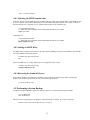
5.1 System Status ............................................................................................................................................. 74
5.2 Active Users................................................................................................................................................ 74
5.3 Event Viewer .............................................................................................................................................. 74
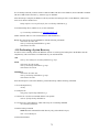
5.4 AP Status and Transit Link Graph.......................................................................................................... 74
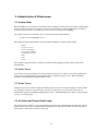
5.5 System Check ............................................................................................................................................. 75
5.6 System Verification.................................................................................................................................... 75
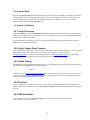
5.6.1 Verify Processes............................................................................................................................75
5.6.2 Verify Captive Portal Features ...................................................................................................75
5.6.3 Speed Testing................................................................................................................................75
5.6.4 Ping Test .......................................................................................................................................75
5.6.5 DNS Verification ..........................................................................................................................75
5.6.6 Verify APs.....................................................................................................................................76
6 Software......................................................................................................................................................... 77
6.1 Software Upgrades & Patching ................................................................................................................ 77
6.2 Logs and Log Rotation .............................................................................................................................. 77
6.3 Log Location .............................................................................................................................................. 77
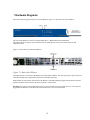
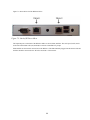
7 Hardware Diagrams ..................................................................................................................................... 78
8 Technical Support......................................................................................................................................... 81
4
The information in this User Manual has been carefully reviewed and is believed to be accurate. AllCity Wireless
assumes no responsibility for any inaccuracies that may be contained in this document, makes no commitment to update
or to keep current the information in this manual, or to notify any person or organization of the updates. For the most upto-date version of this manual, please visit the AllCity Wireless support website at
http://www.allcitywireless.com/support/. AllCity Wireless reserves the right to make changes to the product
described in this manual at any time and without notice. This product, including software, if any, and documentation
may not, in whole or in part, be copied, photocopied, reproduced, translated or reduced to any medium without prior
written consent.
IN NO EVENT WILL ALLCITY WIRELESS, LLC. BE LIABLE FOR DIRECT, INDIRECT, SPECIAL,
INCIDENTAL, OR CONSEQUENTIAL DAMAGES ARISING FROM THE USE OR INABILITY TO USE THIS
PRODUCT OR DOCUMENTATION, EVEN IF ADVISED OF THE POSSIBILITY OR SUCH DAMAGES. IN
PARTICULAR, ALLCITY WIRELESS, LLC. SHALL NOT HAVE LIABILITY FOR ANY HARDWARE,
SOFTWARE, OR DATA STORED OR USED WITH THE PRODUCT, INCLUDING THE COSTS OF REPAIRING,
REPLACING, INTEGRATING, INSTALLING OR RECOVERING SUCH HARDWARE, SOFTWARE, OR DATA.
Any disputes arising between manufacturer and customer shall be governed by the laws of Anne Arundel County in the
State of Maryland, USA. The State of Maryland shall be the exclusive venue for the resolution of any such disputes.
AllCity Wireless’ total liability for all claims will not exceed the price paid for the hardware product. Unless you
request and receive written permission from AllCity Wireless, you may not copy any part of this document. Information
in this document is subject to change without notice. Other products and companies referred to herein are trademarks or
registered trademarks of their respective companies or mark holders.
Copyright 2011 by AllCity Wireless, LLC.
All rights reserved.
Printed in the United States of America
Revision History
Date
Editor Description
Rev
1.0
11/11/2007 JLB
Initial Draft
1.01
11/23/2007 JLB
Minor Formatting Edits
1.02
12/19/2007 JLB
minor edits
1.3
10/25/2008 DV
Updated for version 1.3.1
1.3.2
3/5/2010
Updated for all Hardware
1.5
11/23/2010 DV
PM
Updated for version 1.5
5
Preface: About This Manual
This manual is written for system administrators, system integrators, network administrators and others who use the
WiDirect appliance. The WiDirect models span a broad spectrum of possible applications. The product can be used to
manage wire line and wireless networks, both local and remote. The WiDirect line is split into two classifications, Auth
Server and Client. All networks initially require a WiDirect Auth Server which has the ability to function independently.
Through WiDirect Client Management Service (WCMS) clients can be added to expand the network size, both from user
processing and to expand in different geographic locations. The smaller models are appropriate for small office
applications and local WISP applications. Larger models can manage common carrier network environments. Each
WiDirect unit contains the same software and most of the features are available for use in each model, most notable
differences pertain to embedded firmware and Micro model line. The feature set within the WiDirect appliance is broad
and is expected to continue to grow over time. These features provide significant capabilities that create a network
infrastructure, one that can be used in numerous creative ways depending on the environment.
If you are installing a WiDirect for the first time, you should read this entire manual in order to become familiar with the
settings and tools. However, the steps to actually install and configure a new WiDirect box begin with Section 3:
Installation.
6
1 WiDirect Administration Interface
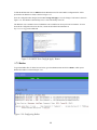
1.1 Logging In
In order to gain initial access to the WiDirect's web based GUI, a cross-over cable can be connected to the ETH1
(Ethernet 1) interface to another computer such as a laptop. Once physically connected, the WiDirect provides the other
machine with an IP address in the 10.4.1.0/24 subnet via DHCP. (Be sure that the connecting computer is configured for
DHCP to receive the IP address.)
Once the IP address has been established, open a web browser such as Firefox, and open the following URL:
http://10.4.1.1/portal/admin
This URL opens the WiDirect Admin login page. To login, use the preconfigured username of admin and the password
widirect.
Note: If the IP address of Eth1 has changed from the default, use the new IP address instead of 10.4.1.1.
WARNING: For security reasons, if a user fails to enter the proper login credentials three times in a row, their IP
address will be banned from the login page for fifteen minutes. After fifteen minutes has passed, they'll be able to
attempt another login.
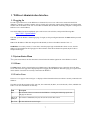
1.2 System Status Menu
The system status menu is the first menu that is located in the left hand navigation bar of the WiDirect web GUI.
1.2.1 Home
The Home button, which is located in the top left hand corner of the administrator page, returns the user to the home
screen. This is the same page that is displayed upon first logging into the WiDirect. The home page gives a quick status
on the number of users that are currently connected to the WiDirect.
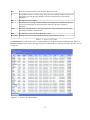
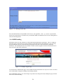
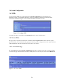
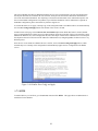
1.2.2 Active Users
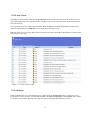
The Active Users page as shown in Figure 1-1 displays all the information about users that are currently connected to the
WiDirect.
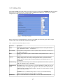
The table provides the username, traffic, start time, time connected, IP, MAC, Access Point (AP), Client, and SSID. See
Table 1-1 for more information on each entry.
Field
Description
User
The username of the user connected to the WiDirect. Clicking this links brings up the user
edit page for that user.
InBytes &
OutBytes
The amount of bandwidth (in bytes) the user has used for this session
Start Time
The date and time the session began
7
Time
Total time connected for this session in Hours: Minutes: Seconds.
IP
The IP address the user is currently using. If the network has multiple WiDirect clients, users
may appear to be using the same IP address. (Because each client has its own network
behind NAT.)
MAC
The user's current mac address.
AP
The AP the user is on. Only available if Radius accounting has been enabled in the firewall.
See Firewall configuration for more information. Otherwise, the AP will display as
“unknown”
Client
This is the client that the user is currently connected to. Only useful if there are more than
one WiDirect machines on the network.
SSID
The SSID the user has associated with for this session.
Disconnect Clicking on this link will automatically disconnect the user from the network.
Table 1-1: Active User Fields
The Disconnect button at the end of each row allows administrators to quickly disconnect individual users. There is a
Disconnect All button at the bottom of the page that allows an administrator to completely disconnect all active users in
a single step.
Figure 1-1: Active Users Screenshot
8
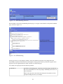
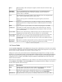
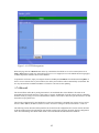
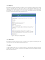
1.2.3 Event Viewer
The WiDirect’s Event Viewer, which is in the System Status menu, provides a time line of activity in the network. It
shows administrator log-in time, AP status checks, watchdog events, process start/stop actions, client monitoring, and
other system activity.
Events are rated on Severity, which ranges from Info, Alert, and Critical. If needed, administrators can obtain more
detailed event information in the Reports section, which allows sorting by severity.
Note: The Event Viewer page also displays the local current system time, which allows administrators to quickly figure
out timing of recent events.
Figure 1-2: Event Viewer Page
1.2.4 AP Status
WiDirect administrators can use the AP Status page, which is under the System Status menu, to monitor the Access
Points on their wireless networks. Access Points are added in the System Configuration->Access Points menu, which is
covered later in this manual. This page only reports the status of configured and enabled access points.
9
Every Access Point that has been enabled will automatically be monitored by the WiDirect. This page provides a quick
overview of an up/down status of the Access Points, as shown in Figure 1-3. Each AP lists Status (up/down), Name, IP,
and Last Ping Time. If the AP Name is clicked, the WiDirect opens the detail page for that AP, which lists all the
information that has been gathered via network monitoring. Last ping Date is the last time the WiDirect successfully
pinged the AP.
Figure 1-3: AP Status Page
The View Transit Link Graph button provides a real time view of the wireless mesh TL links. This page not only shows
which APs have neighbors, but also provides the TL signal strength and the current number of associated users on the
AP. Figure 1-4 shows a sample TL graph link page. Although considered real time, this graph only updates every 5-10
minutes due to the amount of SNMP polling data to collect per Access Point on the network.
Note: The TL graph page also displays the serial number of the AP as well as the time the graph was generated.
Figure 1-4: TL Graph Sample
10
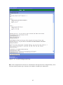
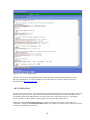
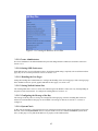
1.2.5 System Check
The System Check page under the System Status menu displays a snapshot of the current health of the WiDirect system,
as show in Figure 1-5. This page analyzes important system functions, such as Radius, DNS, DHCP, Firewall, NTPD,
PreProxy, Squid, and FTP services by establishing if they are running or not. If for any reason a service has been
disabled, clicking on the Control button next to each process in order to re-enable it.
Although the WiDirect has a built in watchdog program that automatically restarts any WiDirect process that has failed,
it will not restart any process that the administrator has explicitly stopped. For example, if the administrator stops
Radius via the control window, the watchdog program understands this action and will not attempt to restart Radius.
However, if the Radius process dies, the watchdog will automatically restart the process without Administrator
intervention.
Other information that can be found on this page is Interface Settings, Routing table, NTP status, and Network
statistics. When contacting AWI technical support, the data on this page will be used to troubleshoot the health of the
WiDirect.
Figure 1-5: System Check
11
1.3 Users Menu
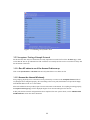
1.3.1 Viewing All Users (List All)
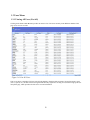
Clicking on the Users->List All menu provides an extensive list of all users currently in the WiDirect database. This
page views 25 users at a time.
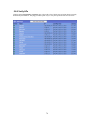
Figure 1-6: List All Users
This screen shows a snapshot of all users stored in the database, displaying their username, first and last names, status
(active, expired, etc.), the date of their last login and the date they registered. Clicking on a username brings up the user
edit profile page, which provides all of the user’s account information.
12
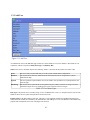
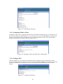
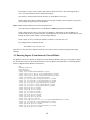
1.3.2 Find User
If a customer forgets their username or password or wants to change their contact information, this page allows
administrators to quickly search for the user.
Figure 1-7: Find User
To find a user, enter at least one piece of information about the user, such as username, last name, first name, email
address, password, or MAC address and click the Lookup User button. The WiDirect will search the database for the
information provided and display any matches that it finds.
1.3.2.1 Find User Wildcards
Wildcard searches are supported with the character %. For example:
z Find a username that begins with b and ends with y, use "b%y"
z Find a username that contains the word smith, use "%smith%"
z Find all email address that end with hotmail.com, use "%hotmail.com"
If multiple matches are found on the provided search criteria, the WiDirect provides the administrator with a list of all
matches.
13
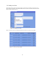
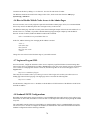
1.3.3 Add User
Figure 1-9: Add User
An administrator can use the Add User page to add a user to the WiDirect’s local user database. Most fields are self
explanatory with the exception of Status, Plan Type, and Primary Mac.
Status can be Active, Disabled. Expired, or Purchasing. Table 1-2 describes all the possible user status codes.
Active
The user is fully activated and ready to use the system without further configuration.
Disabled
The user has been effectively banned from the network and can never relogin back in without
Administrator help.
Expired
The user’s plan has expired and the user will be asked to select/purchase a new plan upon their next
network login.
Purchasing
The user has been registered but has not purchased a plan, which is useful for creating an account
and still having the user to be challenged for a plan selection on their next login.
Table 1-2 User Status Types
Plan Type is the plan the user is currently using. If a user is added and set to active, a valid plan must be selected. The
WiDirect shows all active plans in the pull down menu for this item.
Primary MAC is the MAC address of the user. This entry is only important if MAC based authentication has been
enabled and can normally be left blank by the Administrator when adding a new user. The WiDirect will automatically
populate this field upon the user's next valid login to the network.
14
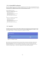
1.3.4 Banning MAC Addresses
In the event that a computer is found to be engaged in malicious or unfavorable behavior, an Administrator can ban the
MAC address from the network via the MAC- Banned page under the Users menu. On this page, simply click Add
MAC which asks for the MAC address to ban.
Administrators can also remove bans from this page by clicking the delete button next to the MAC address.
Figure 1-10: Banning a MAC from the network
15
1.4 User Experience Menu
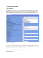
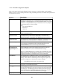
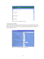
1.4.1 Preferences
The Preferences page, shown in Figure 1-11, allows an Administrator to define the look and feel for users of the
network. For example, the redirect page field forces each user to see a specific web page upon logging onto the
network. This might work for attendees at a conference to see the day events, a townhouse community to see the
home owner’s associations rules and regulations, or even expose end users to a splash page of advertisers.
Figure 1-11: Preferences
The default entries for each field, which is described in the table below, provide the default behavior of each setting.
Administrators can override each setting at the SSID level. If an entry is configured in the SSID settings submenu,
the SSID level setting will be used if the user connects to the SSID.
If no setting is configured in the SSID settings submenu, the default setting will be used.
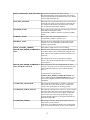
Field Dependencies - (Default vs. Per SSID) User experience preferences can be either a global default setting or an
SSID specific parameters.
16
MAX_CONNECTION_TIME_SECONDS The maximum connection time before a user is
disconnected and they need to login again. This setting is
useful for Advertising based networks, where users should
view the login ads at intervals.
MAX_IDLE_SECONDS
Maximum time in seconds that an idle user is allowed to be
connected. If no traffic is passed on their connection, they
are considered idle and once idle for this many seconds,
they are disconnected from the WiDirect.
NETWORK_NAME
Name of the network, displayed in the login page and terms
and conditions and where ever the
%NETWORK_NAME% variable is used in the branding
section.
COMPANY_NAME
Name of ISP, used in the branding wherever
%COMPANY_NAME% variable is used.
REDIRECT_PAGE
The page the user is redirected to upon logging into the
network. Leave this field blank to redirect user to their
originally requested URL.
EMAIL_SUPPORT_ADDRESS
Email address displayed to the user in branding.
ALLOW_MAC_BASED_AUTHENTICA Firewall section must be properly configured in order for a
user's MAC address can be established by using the user's
TION
MAC address as the validation instead of usernames and
passwords.
This setting allows the user to bypass the login page.
However, they must still start their browser to be 'logged'
into the system.
ALLOW_MAC_BASED_AUTHENTICA This setting allows users to be authenticated via radius
messages. As soon as a user is connected to the mesh, they
TION_WITHOUT_SPLASH
will be authenticated into the system without starting a
browser.
In order for this to work properly,
ALLOW_MAC_BASED_AUTHENTICATION must
also be enabled AND the getapfromradius must be set in
the firewall configuration. See firewall section for more
information
VALIDATION_SEND_EMAIL
This setting tells the WiDirect to send the “verification”
email to the user. In this email, the user is requested to
“Verify” their email address by clicking on a link.
VALIDATION_PUBLIC_WEB_IP
The public IP or domain of the web server, which is used in
the Verification emails sent to newly registered users. In
this email, the user must click on a URL to validate their
account. This must also be properly filled in to accept
payment through Authorize.net or PayPal. This field sets
the domain of that URL
VALIDATION_PERIOD
This setting is currently unused by the system and is for
future releases of the software.
In the future, it will define the number of seconds (usually
1 day or more) that the user has to click on the validation
17
email URL before their account is disabled.
In other words, if they do not validate their email address
by clicking on the URL in the validation email, their
account will be suspended until they do.
VALIDATION_FROM_ADDRESS
The email address that a user sees verification emails
originating from.
VALIDATION_PERIOD_TEXT
The amount of time in text format that is displayed to the
user in the validation email. Instead of saying the amount
of seconds that's defined in the
VALIDATION_FROM_EMAIL, this allows the
administrator to define a more human readable form of the
amount to time. For example, '1 day' might be a desirable
value instead of saying 38640 seconds.
DISABLE_USER_PASSWORD_AUTOR If enabled, the “Forgot Password?” link will be removed
from the login page. This is a security parameter that can
ECOVERY
be used at the administrator’s discretion.
Set 1 to enable, 0 to disable.
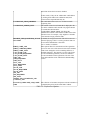
FIRST_NAME_ASK
FIRST_NAME REQUIRED
FIRST_NAME_TEXT
LAST_NAME_ASK
LAST_NAME_REQUIRED
LAST_NAME_TEXT
ORG_ASK
ORG_REQUIRED
ORG_TEXT
CITY_ASK
CITY_REQUIRED
CITY_TEXT
STATE_ASK
STATE_REQUIRED
STATE_TEXT
ZIP_ASK
ZIP_REQUIRED
ZIP_TEXT
TERMS_AND_CONDITIONS_ASK
CAPTCHA_ASK
These options allow for customization of the registration
process for new users of the network. Each of the standard
fields can be changed to ask for something different, or
disabled completely. The captcha, a security code used to
prevent automated registrations, can also be enabled to
prevent automated account registrations. The text of the
terms and conditions can be edited in the SSID branding
section.
COLLECT_USERNAME_AND_PASSW
ORD
The collection of usernames and passwords can be disabled
if authenticating users based on their MAC address.
Table 1-3: Preferences Options
18
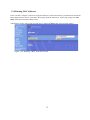
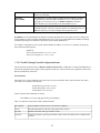
1.4.2 Walled Garden
The WiDirect’s Walled Garden allows administrators to host local content (e.g., community website) that can be
integrated into the captive portal-landing page. For example, administrators might want their users to go to
google.com without network authentication. In order to allow this, only “.google.com” needs to be added to the
Walled Garden list. The WiDirect can also be configured to automatically search for web pages to add to the walled
garden. This allows for the user to browse a web site and all the sites linked to from that web site. If some sites do
not need to be crawled as deeply as others, the depth to be crawled of each site can be specified on the same line as
the site. As the Walled Garden Crawler may not be able find all sites that are needed to display a web page properly,
it is a good idea to test that the pages are displaying correctly and add additional sites as needed.
Figure 1-12: Walled Garden
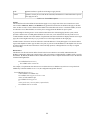
1.4.3 Message of the Day
The Message of the Day (MOTD) feature allows administrators to create messages that appear on the login screen.
When the user is prompted for the username and password, the message of the day will also be displayed depending
on how the branding is configured. See the branding section for more information on how the MOTD is displayed
on the login screen.
19
Figure 1-13: Message of the Day
The entire MOTD field can accept HTML code. However, only hyperlinks, <font>, <p>, and <br> tags should be
used to keep any distortion to a minimum. Any external links added to the MOTD need to be in the walled garden or
in the firewall configuration.
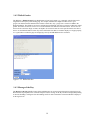
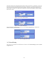
1.4.4 SSID Branding
All WiDirect units come with a default set of fully implemented authentication portal pages. This is a completely
functional Captive Portal and can be used to perform all needed authentication related functions. New users may
sign up through this portal by entering their desired login/password, name, contact information, and billing
information. The included portal may be modified to include customized graphics and textual information such as
usage agreements and contact information.
Figure 1-14: Sample Login Page
To customize these Authentication pages, click on SSID Branding link under the User Experience menu. From here,
select which SSID to change the branding on the branding edit page.
Select the Preview button to view what the login, Forgot Password, Change Password, and Register pages will look
like to users with this branding.
20
Figure 1-15: SSID Branding Selection
When an SSID is selected from the Branding Selection page, a new page is shown that lists each possible brandable
page, as shown in Figure 1-16.
Figure 1-16: SSID Branding
On this page, there are Login, Register, Purchase, Terms & Conditions, Forgot Password, Change Password,
Expired Page, Stylesheet, and Verification email templates. Each page has certain keywords that it supports. Each
page has a list to the right that describes which variables are valid for that page.
For example, the Login page allows the following variables.
%%HTML%%
Available on all branding pages. Used when referencing images and other files
that exist on the WiDirect. See the Using Images in Branding section below for
more information.
NOTE: This must also be used when referencing the CSS stylesheet. See the
example branding file below as an example.
21
%%MOTD%%
The WiDirect replaces this with the text from the MOTD.
%%ERROR_MESSAGES%%
If there was an error message, such as “Incorrect Password”, this variable tells
the WiDirect where to place that information.
%%LOGIN_FORM%%
Where the login form will be displayed. This variable IS REQUIRED for the
login branding page.
Table 1-4: Login Form Branding variables
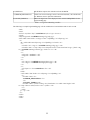
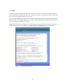
The following is a sample login branding page. All the variables have been bolded to make it easier to read.
<html>
<head>
<link rel="stylesheet" href="%%HTML%%/style.css" type="text/css">
</head>
<body background="%%HTML%%/images/bg_body.jpg">
<table width="500" border="0" align="center" cellpadding="0" cellspacing="0">
<tr>
<td><table width=500 cellspacing="0" cellpadding="0" border="0">
<tr>
<td width="32"><img src="%%HTML%%/images/logo.jpg"></td>
<td width="468"><a href="http://www.annapolis-wireless.com/contact.html" target=_blank><img
src="%%HTML%%/images/banner.jpg" border=0></a></td>
</tr>
<tr>
<td bgcolor="#ad0006"></td>
<td bgcolor="#ad0006"></td>
</tr>
<tr>
<td><img src="%%HTML%%/images/photo1.jpg"></td>
<td><img src="%%HTML%%/images/photo2.jpg"></td>
</tr>
<tr>
<td colspan=2><h3>%%MOTD%%</h3></td>
</tr>
</table>
<table width="500" border="0" cellspacing="0" cellpadding="0">
<tr>
<td width="200"><br>
%%ERROR_MESSAGES%% <br>
<br>
%%LOGIN_FORM%%</td>
<td width="300"><iframe scrolling="no" frameborder="0" width="300" height="250"
src="http://adserver.allcitywireless.com"></iframe></td>
</tr>
</table>
<p> </p></td>
</tr>
</table>
</body>
</html>
22
1.4.4.1 Using Images in Branding
On the Branding Edit page, there is also an area at the bottom of the screen that allows images to be uploaded for
the branding. After uploading, the images can be referenced in any of the branding pages (except stylesheet) by
using the following convention:
<img src=”%%HTML%%/images/imagename.gif”>
The imagename.gif is the name of the image to be displayed. The WiDirect will automatically replace
%%HTML%% with the correct URL information. If the %%HTML%% keyword is not listed, the image will not be
displayed correctly.
WARNING: Be careful about HTML construction. If unsure, Administrators can use the preview button to view
what the branded pages look like.
Just about anything can be changed, including the login form by editing the Stylesheet portion of the branding. With
the exception of the variables described in the previous section, any HTML code is valid in the branding pages.
Unfortunately, listing all the possible HTML tags is outside the scope of this document. To learn more about HTML
tags and page construction, see the guide at http://www.w3schools.com/html/
23
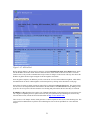
1.5 Reports
1.5.1 Functionality Overview
The WiDirect is able provide many reports that are useful in both budgeting and planning on future growth. It is
also important to understand users as well as be able to reach out to them for marketing purposes. Reporting is an
important part of understanding how much the network is used and where it is used the most. Reporting can also
help find potential problems as well as monitoring anomalous behavior for either equipment or end users.
Figure 1-17: Sample Report Output
1.5.2 Connections
The connections report shows connections to a particular SSID in increments of 1 to 30 days, monthly, or annually.
This is a representation of how many individuals presented user credentials and were permitted out onto the internet.
An additional connections report is available that shows the manufacturer of the network cards of the users.
1.5.3 Registrations
Registration report is available in increments of 5 to 30 days, monthly, or annually. This report illustrates how many
people signed up for an access plan in the given period.
1.5.4 Overall Usage
The Overall Usage tab indicates how much the network has been utilized by each user, which is sorted in
descending order. It will give outputs based on both amount of bandwidth used and time spent on the system for any
given date range.
24
1.5.5 Billing (Purchases)
The end user report that details which user signed up for service by username, the date and time they signed up, and
the amount of money associated with the transaction. There is also a confirmation string given that is a unique
identifier of the event. For payment gateways such as Authorize.Net, this string is the result code from the actual
payment transaction. Otherwise, this string is a unique identifier for each purchase, including free plan purchases.
1.5.6 Access Point Usage
The Access Point Usage Report details the amount of usage an Access Point received over a time period. It reports
both bandwidth and the amount of unique end users. This is important to understand if an AP is in a good location
or perhaps it should be a candidate for deployment to a better used area.
1.5.7 Downloads
Some reports are downloadable to CSV files. These reports include user account information, user e-mail accounts,
and event reporting on several severity levels.
25
1.6 System Configuration
1.6.1 SSIDs
To control multiple SSIDs, they must be defined in the System Configuration area of the WiDirect user
management console. Once the SSID is defined it, can use the standard preconfigured look and feel which it
receives from the default settings or it can be customized for different networks or events.
Figure 1-18: Adding SSID
To edit the look and feel of an SSID, see the Branding discussion earlier in this document.
1.6.2 Access Plans
This page works in conjunction with the local user database and the Captive Portal. It allows end users to pick a
plan for which they will be billed when they sign up and when they need to recharge their account. A plan is defined
by the Administrator and restricts the amount of usage time a user can have.
1.6.2.1 Access Plans Page
The Access Plans page under the System Configuration menu lists the available access plans to end users. Figure
1-19 shows this page, which lists all the currently available plans. To create a new plan, click on the Add Plan link.
Figure 1-19: Access Plans
26
1.6.2.2 Adding a Plan
From the Access Plans page under the System Configuration menu, just click on the Add Plan link which is located
under the list of current Access Plans. This brings up the Adding Access Plans page, which allows for detailed
configuration of a plan. This page is shown in Figure 1-20.
Figure 1-20: Plan Creation
If there is only one free plan defined in the system for a given SSID, users will not be given a choice of plan
selection. They will be automatically assigned to the single plan.
Table 1-5 describes all the fields for plan creation.
Keyword
Description
Name
A descriptive name for the plan. This name is displayed to users on the plan selection
page. (alphanumeric field, 1 – 100 characters)
Firewall ID
A unique ID for each plan from 101 to 200 (numeric field, 3 characters). If unsure, use
the default number given.
Days
Number of days duration a plan is valid for (numeric field, possible values 0 – 999, 0=
unlimited)
Minutes
Number of minutes duration a plan is valid for. Note: Do not use minutes if the days
setting is being used. This is only used for plans that can be expressed in terms of
minutes, such as 1 hour account access plans. (Numeric field, possible values 0 – 999,
0= unlimited)
Bandwidth Up
Bandwidth limitation in kbps a user is allowed to upload from their machine. (numeric
field, unit of measure: kbps, 0= unlimited)
Bandwidth Up
Burst
Bandwidth in kbps a user is allowed to use if extra bandwidth is available. (No one else
is using the system) For example, you might have a 200 up limit but a 400 burst limit,
which gives users extra bandwidth if available. In most cases, set this value to the same
as the bandwidth up setting.
WARNING: Do not set Bandwidth Up Burst to a value lower than Bandwidth Up
setting. (numeric field, unit of measure: kbps, 0= unlimited)
Bandwidth
Same as bandwidth limitation as Bandwidth Up, but for defining download speeds.
27
Down
Measured in kbps 1024 would equal 1 megabits (numeric field, unit of measure: kbps,
0= unlimited)
Bandwidth
Down Burst
Same as bandwidth limitation as Bandwidth Up Burst, but for defining download
speeds. Measured in kbps 1024 would equal 1 megabits (numeric field, unit of
measure: kbps, 0= unlimited)
Cost
The amount the user must pay in order to receive the plan. If set to zero, the plan will be
“Free”. (currency field, unit of measure: USD, 0= free)
Note: To collect payment via the WiDirect, the payment gateways must also be
configured.
Default
If the plan is set to default and if no user SSID is available or the user's SSID doesn't
match any plans that are configured specifically for a SSID, this plan will be available
to the user.
SSID
Applies this plan to a specific SSID, or leave blank if the plan applies to all SSIDS
Ad Interval
The number of seconds in between the display of the advertisement page. Postproxy
must be enabled in the firewall configuration file for this feature to work. See section
1.7.4.1 for more details.
Content Filter
Whether or not content filtering is disabled. Postproxy must be enabled in the firewall
configuration file for this feature to work. See section 1.7.4.1 for more details.
Login Allowed
on any SSID
If this option is set to Yes, an account created with this access plan can be used on any
SSID in the network. If both this option and the Default option are set to No, then
accounts created on this access plan will only be able to login on the SSID specified in
the SSID field.
Delay Before
Repurchase
This option is to limit the frequency that a user may reselect an access plan. Setting this
value to 30 would only allow the access plan to be selected once per month.
Table 1-5: Plan creation fields.
1.6.3 Access Points
From the System Configuration->Access Points menu, this page allows administrators to list all the Access Points
for their network. By entering an Access Point, the WiDirect is able to monitor and configure the access point. This
page lists all the currently configured Access Points, as shown in Figure 1-21.
Adding access points to the system enhances future troubleshooting and configuration. For example, on Nortel
networks, it is very important to properly configure the Radius configuration files. By taking the time and entering
all the AP information requested on this page, the WiDirect can use this information to assist during the Radius
configuration step. For example, in the WiDirect helps the administrator build Radius files based off the serial
number of the Access Point.
On the main access point page, administrators can edit or add new Access Points. By clicking on an Access Point or
clicking Add New Access Point, an Access Point Edit page will be displayed as shown in Figure 1-22. Table 1-6
describes all the possible values for this page.
Keyword
Description
MAC
The MAC address of the AP. This must be unique across all access points. The MAC
can frequently be obtained from a sticker on the AP. REQUIRED
IP
The IP that the system will use to ping the AP, such as 10.3.1.50. This field MUST be
filled in with a valid IP address for monitoring and data collection. REQUIRED
Alternate IP
This optional field is used to specify a secondary IP address for the access point. When
28
using Tropos access points, this field is required on any access points that are connected
directly to the WiDirect.
Type
Set's the AP type. Choices: Nortel, Proxim, Tropos, BelAir, EnGenius, Other. Some
access points have an automatic configuration option as well. If that option is chosen the
WiDirect will automatically configure the access point.
Name
A descriptive name of the AP. This field should be kept relatively short (10-20
characters), because it is used in the TL graphing pages and visual management
components. REQUIRED
Location
A description of the AP, used only on the configuration page.
Contact Info
Email address of the user who should get emailed on an up/down event. If no email
address is defined, no email will be sent on up/down events.
Serial Num
The access point’s serial number, NNTMNO000UD (example) For Nortel access points,
this is required to generate the keys in the radius file. REQUIRED
SNMP
The SNMP public community string. If unsure, use the default of “public”.
Latitude
Location of the AP, used only on the configuration page.
Longitude
Location of the AP, used only on the configuration page.
Mode
This Field identifies the access point as being connected to network backhaul (@NAP)
or as a standard meshing access point (SAP) REQUIRED
Status
Dropdown field for defining the operational status of an access point (enabled /
disabled) If an AP is 'disabled', it will not be monitored by the WiDirect. REQUIRED
Username
This field tells the WiDirect the telnet/web username for the Access Point. The default
Nortel username is 'admin'
Password
This field tells the WiDirect the telnet/web password for the Access Point. The default
Nortel password is 'admin'. When editing an access point this field can be left blank for
the password to remain the same.
Table 1-6: Keywords and Descriptions for Access Points
Figure 1-21: Access Points
29
Figure 1-22: Adding a New Access Point
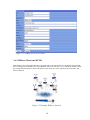
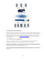
1.6.4 WiDirect Clients and WCMS
Each WiDirect client controls discontinuous or geographically separated networks over the Internet using WCMS.
All user management is handled by the central WiDirect Auth server, but after a user is authenticated all their traffic
goes straight from the WiDirect Client to the Internet. If one client goes down, only the people connected to that
client are affected.
Figure 1-23 Example WiDirect Network
30
Figure 1-23 shows an example of a network with a WiDirect and WiDirect client at remote locations. Even though
each of these clients lies on a separate network, they can all be setup to connect to the central WiDirect
authentication server, which allows a common user base to be defined across all the WiDirect Wireless networks. To
the user, all the WiDirect networks appear to be under a single entity.
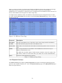
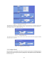
To configure the list of WiDirect clients, click WiDirect Clients under the System Configuration menu. To add a
new client, click the Add a Client link at the bottom of the WCMS Client Administration page. Table 1-7 lists all
the fields for this page.
Figure 1-24: WiDirect Clients Page
Keyword
Description
Description
The name of the WiDirect server. The built in “local” client is always named Local WiDirect.
Location
Text that describes the physical location of the WiDirect client.
Contact Info
Email address of the administrator that should be emailed when up/down events occurs for the
client.
GWID
This is a unique identifier for each WiDirect. This field MUST be entered in correctly for
WiDirect communication to occur.
The GWID value is the MAC address of ETH1 interface without the colons. For example, if the
MAC address of ETH1 was 00:00:0A:BC:DE:1F, the GWID value would be 00000ABCDE1F.
Status
Provides the enabled/disabled of the WiDirect.
Table 1-7: WiDirect Client Fields
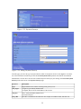
1.6.5 Payment Gateways
The Payment Gateways page under the System Configuration menu allows for defining and managing payment
gateways, such as PayPal or Authorize.net. Once at the Payment Gateways page, click Add Payment Gateway to
add a new Payment Gateway.
31
Figure 1-25: Payment Gateways
Figure 1-26: Adding Payment Gateway
From this page, just select the type of payment desired, which is a drop down list next to the Type slot. Fill in the
rest of the information remembering to click the Create Payment Gateway button at the bottom when finished.
Administrators can also choose to look at the available Payment Gateways by the clicking on the List All Payment
Gateways link at the bottom of the Payment Gateways page.
Keyword
Description
Type
Paypal/Authorize.Net. Defines which payment gateway to use.
GW_Login
“Login” key provided by Authorize.Net
For PayPal, this will be the email address of the account.
GW_Key
“Key” Value provided by Authorize.Net
Not used for PayPal
GW_URL
The URL to authenticate the transaction. For example, for Authorize.NET, this URL will
32
typically be https://secure.authorize.net/gateway/transact.dll. For PayPal, this will be
https://www.paypal.com/cgi-bin/webscr.
Email
The email address of the account that is registered with the payment gateway.
Status
Enabled or Disabled. When a gateway is disabled, it will not be presented to the user as a
payment option.
SSID
The SSID that the payment plan is used. If this field is blank, the payment gateway will be
available for all SSIDs.
Table 1-8: Fields for adding payment gateways.
Once the forms are all filled out, click Create Payment Gateway to activate this payment gateway.
PayPal Note:
In order for PayPal to work properly, the VALIDATION_PUBLIC_WEB_IP in the preferences section must be set
to the public IP address of the WiDirect. This is because the PayPal server makes a separate return call for each
transaction called the IPN.
1.6.6 Network Configuration
Figure 1-27: Network Configuration
Accurate network configuration IP addressing is critical to the proper operation of the WiDirect. All network
configuration and routing configuration is controlled via the Network Configuration page under the System
Configuration menu. Figure 1-27 shows the Network Configuration window.
This page allows configuration of the WiDirect interfaces, the default route and the DNS servers. The first section
allows the administrator to set which interface is to be used as the WAN interface. By default the WAN interface is
ETH0. If DHCP is enabled the Default Route and DNS server fields will be disabled, because that information will
be retrieved via DHCP.
By default the ETH0 interface is configured for DHCP, while the ETH1 interface uses the standard 10.4.1.1
addressing scheme. IP addresses are not set for ETH2 or ETH3.
33
The bottom of the Network Configuration page has buttons to add a VLAN interface or a subinterface. A VLAN can
be used on any interface to help separate users on the network. A subinterface is a secondary IP on the interface that
will be on the same local network as the main interface IP address. The pages to add a VLAN or Subinterface are
shown in Figures 1-28 and 1-29. To add a VLAN or subinterface you must enter an IP address, netmask, and an ID
number from 1 to 4095.
Figure 1-28: Create VLAN Interface
Figure 1-29: Create Subinterface
After the interfaces have been added they will show up on the Network Configuration page. From there the
interfaces can either be updated or deleted.
Figure 1-30: Network Configuration Page
1.6.7 Network Routing
Static routing can be configured via the administrative GUI interface in the Network Routing page under the System
Configuration menu.
34
Figure 1-31: Network Routing Page
To add a route, simply click on Add a Route at the bottom of the screen. Fill in the information required and click
the Submit button.
1.6.8 Date and Time
Select Date and Time under the System Configuration menu. From the drop down menus, set the time zone, date
and time. Don’t forget to click the Update button next to the appropriate commands to implement your selections.
Figure 1-32: Date and Time
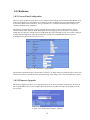
1.6.9 Log Viewer
With the Log Viewer page, located under the System Configuration menu, log file scan be viewed in real-time.
Choose the appropriate log file by clicking on the link and a separate screen opens to view the log. This page will
update as new entries are being added to the log file.
35
Figure 1-33: Log Viewer
1.6.10 License Key
The WiDirect comes preconfigured with a certain number of user licenses depending on the WiDirect model. There
are two types of user classifications for licenses; Active Users and Concurrent Users. An Active User is a user that
has been registered and is eligible to use the network. Users that have been disabled or expired do count towards the
Active User count. Concurrent Users are the total number of users that can be using the system simultaneously at a
given time. Once the maximum number of concurrent users has been reached, new users must wait for a currently
connected user to disconnect before using the network.
If needed, new license keys can be added to the WiDirect. To add new licenses, select License Key under the System
Configuration menu. Browse to the directory where the license file is located on the local machine and then click
Upload. The WiDirect will add the new license files to the database and the end user counts will be reflected in the
license key tab.
Figure 1-34: License Key
Depending on usage of the system and the license that was originally purchased, a new license may need to be
purchased to support more users. Contact support at AllCity Wireless if a new license is required.
36
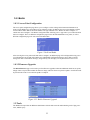
1.6.11 Admin Users
Figure 1-35: Admin Users
The Admin Users page allows the administrator to add and remove administrative accounts, change access levels,
contact information, or even reset passwords.
Opening Admin Users under the System Configuration menu shows the list of administrators for the WiDirect
device. Each administrator is assigned a user level that defines his/her access restrictions. Each administrator can
have full (Administrator) or restricted (Report and Status Only) access to the administrative areas within the
WiDirect.
1.6.11.1 Add New Administrator
In the User Admin screen of the WiDirect (pictured above), click on Add Admin User.
Figure 1-36: Add New Administrator
37
Fill in all the fields and click the Add User button. All fields should be self explanatory with the exception of User
Level, which is described in the next section.
1.6.11.2 Change User Level
The customer can change any Administrator’s role by selecting the desired new role from the drop down menu after
clicking on the user’s name and going into their profile. There are two user levels; Administrator and Reports &
Status Only. An Administrator level user has complete and total access to the WiDirect GUI system. A Reports &
Status user can only view/edit WiDirect users, run status checks, and reports. The Reports & Status level user is a
good setting for phone support staff.
1.6.11.3 Change Password
Each Administrator has a password that allows him or her access to the management console. To change the
Administrator's password, enter the new password in the text box then click on the Submit button. A full access
Administrator can change other administrator’s passwords.
1.6.11.4 Delete
Select this button if you want to delete an administrator.
WARNING: Never delete the admin user. Instead changed the password to something unique and keep it in a safe
location. All administrators should have their own unique usernames and passwords.
1.6.12 Shutdown
The Shutdown page, listed under the System Configuration menu, allows the Administrator to remotely shutdown
or reboot the WiDirect unit. The appliance should never be powered off by disconnecting the power supply.
The shutdown procedure should be run to make sure that the file systems are correctly unmounted. If the WiDirect is
not properly shutdown, it will cause a longer startup sequence the next time the WiDirect is powered up.
WARNING: Use this function with caution. Once the WiDirect unit is remotely shutdown, it can not be restarted
unless someone has physical access to it.
1.6.13 Support
The Support page under the System Configuration menu displays the contact information you can use to contact a
WiDirect professional in case you have additional questions. (Contact information is also listed at the end of this
Manual.)
1.7 Services Menu
38
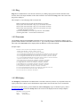
1.7.1 DHCP
The WiDirect provides DHCP services to all available LAN interfaces. Multiple subnets may be defined for each
LAN interface and each subnet has a definable DHCP lease address range associated with it. DHCP can be disabled
on some subnets and enabled on others. Providing DHCP services on multiple subnets makes network
administration easier because static addressing is not required on either subnet. DHCP can be configured to assign a
given hardware Ethernet address (MAC) the same IP every time.
Figure 1-37: DHCP Service
39
To Edit the DHCP table click on DHCP under the Services menu. The entire DHCP configuration file will be
presented in an editable text field, as shown in Figure 1-37.
Once the configuration has changed, use the Save Config and Apply to save the changes. This button is shown in
Figure 1-38. The WiDirect automatically stores a retrievable backup of the file.
The WiDirect uses a standard version of DHCP that can be modified to suit any network environment. To learn
about all the configuration items for this file, consult the ISC DHCP documentation at:
http://www.isc.org/products/DHCPD
Figure 1-38: DHCP 'Save Config & Apply’ Button
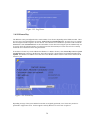
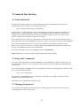
1.7.2 Radius
To generate Radius files for Nortel Access Points, go to the Services menu and click on Radius, which open a
Radius edit window as shown in Figure 1-39.
Figure 1-39: Configuring Radius
40
The only two Radius files that are editable through the GUI are users.conf and clients.conf. For most deployments,
the only file that needs to be edited is the users.conf file, which provides the Nortel Authorization information as
well as the VPN tunnel information. The only thing covered in this documentation is the Authorization portion. All
the rest of the Radius configuration is beyond the scope of this documentation. If more information is required on
the Radius configuration, please consult All City Wireless support site.
As with all the other service pages, a backup copy of the configuration that was modified will be saved automatically
once the Save Config and Apply button at the bottom of the screen is clicked.
Another feature of this page is the Generate New Nortel Data helper button. When this button is clicked, another
page is generated that shows all the correct User-Passwords for Nortel Access Points. If the Access Points have been
added to the WiDirect, they will be displayed at this time. This helper window allows administrators to cut-and-paste
the output into the users.conf section of the radius file. Without this tool, configuring Radius for Nortel can be a very
difficult process.
Once the new Access Points are added to the users.conf file, click on the Save Config And Apply button, which
automatically saves a backup of the configurations and immediately applies the new configuration to the Radius
service.
Figure 1-40: Radius Save Config and Apply
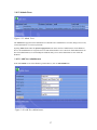
1.7.3 HTTP
To add a HTTP key or Certificate, go to the Services menu and click HTTP. This page allows an administrator to
enable SSL for the WiDirect.
41
Figure 1-41: HTTP Management
While this page also has a Restart button at the top, which allows the HTTP service to be restarted, there are no
Stop or Start buttons on this page. If the HTTP process was ever stopped, access to the Admin and user login pages
would be impossible without a reboot of the WiDirect.
To update the certificates, simply cut and paste them into the Key and Certificate form fields and click Update. If
there is an error with the new key and certificate, the old key and certificate will be automatically used instead. The
new key and certificate installation should be verified in a web browser after updating.
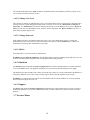
1.7.4 Firewall
The firewall filters traffic that is passing between the LAN and WAN sides of the WiDirect. Firewalls can be
programmed to block traffic based on a wide variety of criteria. Traditionally, firewalls enforce policies to maintain
network security by using a set of rules that determine whether or not traffic is allowed to pass between the LAN and
the WAN on a per-packet basis.
The Firewall configuration file also handles how certain user information is obtained from various services such as
the user's MAC address, IP address, and Access Point. All of these settings are discussed in Tables 1-9 and 1-10.
The following section describes all the possible items for the Firewall configuration file. The first section describes
all the Non-filtering firewall configuration items and the second section describes the traffic filtering configuration
times. Firewall filtering rules dictate which traffic is allowed inbound and outbound of the WiDirect.
42
Figure 1-42: Firewall Configuration Page
Hint: In the configuration file itself, there are commented lines which provide in-line configuration help. These
lines begin with the pound (#) sign. Comments can be added to if needed by the Administrator.
43
1.7.4.1 Firewall Configuration Options
Table 1-9 lists many of the firewall configuration items, such as how to obtain the SSID, AP, IP, and MAC
addresses of users, as well as turning on/off web caching, and adding trusted users. The traffic filtering features are
covered in the next section.
Keyword
Description
ssid
Defines an SSID, along with the IP address range assigned to that SSID. This
command saves processing time by eliminating the need to obtain the SSID
from Radius accounting messages, and is also available when the access point
model does not support Radius messages. The default ssid is set by setting the
start and end ip range to 0.0.0.0. Example:
ssid {
name AnnapolisWireless
start 0.0.0.0
end 0.0.0.0
}
getapfromradius
Tells the WiDirect to obtain the user's Access Point information from the
Radius Accounting messages.
getmacfromradius
Tells the WiDirect to obtain the user's MAC address from the Radius
Accounting messages. This command should only be used if the standard
DHCPD configuration is unavailable (See dhcpdommapi keywords below).
getssidfromradius
Tells the WiDirect to obtain the SSID from the Radius Accounting messages.
Should only be used if multiple SSIDs are configured on the network.
getmacfromdhcp
Tells the WiDirect to obtain the user's MAC address directly from the DHCP
server. In almost all configurations, this command is the preferred over
getmacfromradius because of increased speed and reliability.
dhcpdomapikey
dhcpdomapisecret
dhcpdommapiserver
These keywords are for DHCP communication when using the
getmacfromdhcpd command. If the standard configuration is used on the
WiDirect for DHCP service, these commands should not change.
However, if another DHCPD server is required, these commands will need to
change to point to the other DHCPD server and the new server will need to be
configured for OMAPI. See the dhcpd.conf file for more information.
TrustedIPList
This command allows the WiDirect to allow a set of trusted IP addresses
from the internal side of the network to the Internet without Captive Portal
challenge. The IP addresses should all appear on a single line, separated by
commas. No blank space is allowed between entries. Example:
TrustedIPList 192.168.20.11,10.4.1.20,10.4.1.30
preproxy
Preproxy must be enabled to use the walled garden or landing page feature.
Set preproxy to 0 to disable these features.
landingpage
The landing page is the page the user is redirected to when they start using the
network. If the landing page is not specified, then the user will be redirected
to the login page. The landing page needs to contain a link to the login page
for the user to be able to login. When updating the landing page, the PreProxy
service also needs to be restarted from the PreProxy service page.
postproxy
Postproxy is used to handle web caching, acceleration, monitoring, and
44
content filtering. It is recommended that postproxy be disabled if these
features are not needed.
HostName
SSLAvailable
If the WiDirect has a valid certificate installed, then the HostName should be
set appropriately, and SSLAvailable should be set to yes. This enables the
login page to be accessed securely. In a WiDirect Client the HostName
option should be set to the hostname of the main WiDirect server.
GatewayInterface
The gateway interface is the interface that users are forced to authenticate on.
By default only eth1 is listed as a gateway interface. To authenticate users on
additional interfaces you can have multiple GatewayInterface lines.
Table 1-9: Firewall Configuration Items
WARNING: For all commands that are Radius accounting dependent, the access points need to be configured to
use the WiDirect as their accounting and authentication server. The access points MUST have Radius Accounting
enabled and pointing to the WiDirect as the primary and secondary Radius Server.
For example, if using Nortel Access Points and the WiDirect IP address is set to 10.4.1.1 (default), the ap.ftp file
must contain the following lines:
[RADIUS]
PrimaryAuthenticationServer=10.4.1.1:1812
PrimaryAccountingServer=10.4.1.1:1813
1.7.4.2 Traffic Filtering Firewall Configuration Items
The firewall rules are broken into two RuleSets; Global & Known-users. While there are other defined RuleSets in
the firewall configuration file, editing is NOT supported at this time. AllCity Wireless only supports the Global and
Known-users Rulesets at this time.
Firewall Syntax
Essentially, there is allow and block rules. These rules are processed in FIFO order, which means the first match
wins. Here is an example of firewall rules.
firewall allow tcp port 80 to 10.10.1.1
firewall allow udp to 172.32.1.0/24
firewall block to 172.16.0.0/12
Syntax of the Firewall command is as follows:
FirewallRule action [tcp | udp] [port XYZ] [ to IP][/subnet]
Table 1-10 describes each portion of this command in detail.
FirewallRule
Tells the WiDirect that the rule is a firewall rule, mandatory
action
Describes the behavior of the line, can be either allow or block.
tcp | udp
Optional. Describes what type of traffic to filter
port XYZ
Optional. Describes a specific port to block or allow. Ports value XYZ can be a number from 1
to 65536.
45
to IP
Optional. Defines a specific IP or IP range to apply the rule
/subnet
Optional. Can only be used with the IP command, which defines a subnet rather than a specific
IP to apply the list to.
Table 1-10 : FirewallRule Options
Global
The Global firewall section defines all the rules that apply to every single state of the user's connection. A user's
state could be 'unknown', 'known', and 'disabled'. Any global firewall rules that are defined will apply to all these
states. In other words, if a rule is defined in the Global section that allows the users to a certain IP address, all users
are allowed to access that IP address even if they have not logged into the WiDirect's captive portal.
A good example is allowing users to access advertisement driven sites without logging into the system, which
provides a different sort of walled garden definition. In some cases, some Ad insertion sites only need access to
certain IP address instead of an entire domain. If requirements state that certain Ads are displayed on the user's login
page, this section might be the only way to provide access to the image and links on the login page.
Another instance when users need to be allowed to certain IP addresses if for PayPal support. Users must be able to
login to their PayPal account to pay for their access plan, so port 443 to the IP addresses of the PayPal web site must
be allowed in the firewall. Due to the nature of the secure http protocol, walled garden sites can only use regular
non-secure http.
Known-users
The Known-users firewall section defines firewall rules for users that have successfully authenticated to the
WiDirect. Although it might seem counter intuitive, this section allows an Administrator to DENY traffic to specific
destinations. By default, the WiDirect allows authenticated users to have complete unrestricted access to the Internet
with the following RuleSet:
FirewallRuleSet known-users {
FirewallRule allow to 0.0.0.0/0
}
For example, if requirements state that users are not allowed to access SMTP to any mail server except the local
SMTP relay with an IP address of 10.1.1.10, the configuration might look like this:
FirewallRuleSet known-users {
# Allow SMTP to our SMTP relay
FirewallRule allow tcp port 25 to 10.1.1.100
# Deny all other SMTP traffic
FirewallRule block tcp port 25
#
# Now just let every out everywhere (required rule)
FirewallRule allow to 0.0.0.0/0
}
46
1.7.5 NTP
The WiDirect appliance internal clock must remain accurate for a number of the critical systems to function. In
order to make this work properly, an NTP server is polled to synchronize the internal clock with a known NTP
clock. NTP also provides time services to local devices.
To edit the NTP configuration, go to the NTP page under the Services menu. This is the standard NTP configuration
and it will allow you to change NTPD servers as needed. If more information is required for configuring NTP,
please see the NTP web site: http:://www.ntp.org.
NOTE: This is NOT where you change the local date and time, this is only for Network Time Protocol (NTP). To
configure the Date & Time on the WiDirect, see the Date and Time Configuration section in this document.
Figure 1-43: NTPD Configuration
47
1.7.6 Preproxy
When enabled in the firewall configuration file, the Preproxy service is responsible for redirecting users to either the
login page or the landing page. It also allows users to visit sites on the walled garden without logging in. The
configuration file may be edited to change the number of processes that are running at any given time. Typically the
default settings are fine, but in a large network, or if a lot of content is being displayed to users that are not signed
on, then it is a good idea to increase the number of Preproxy processes.
Figure 1-44: Preproxy Configuration
1.7.7 Web Cache
When enabled in the firewall configuration file, the web caching service is responsible for accelerating user’s web
sites, tracking sites visited, content filtering, and advertisement delivery.
1.7.8 DNS
The DNS configuration page allows you to configure the DNS server. The default DNS configuration only listens
for DNS requests on eth1, eth2, and eth3. If VLANs have been added then the file needs to be updated to respond to
DNS requests on those interfaces.
48
Figure 1-45: DNS Configuration
Figure 1-45 shows the part of the DNS file that needs to be edited to add additional interfaces. Each interface is
listed on its own line. VLAN interfaces would be a combination of the VLAN tag number and the interface name.
VLAN 600 on eth1 would be listed as eth1.600.
1.8 Access Point Support
1.8.1 Nortel
1.8.1.1 FTP
The FTP files can be edited under Services menu after clicking on NORTEL Support then choosing FTP. The file
defines attributes of access points and is pulled from the server every time an access point attempts to join the mesh.
49
Figure 1-46: FTP Configuration
This file is strictly for Nortel Equipment The file is called ap.ftp and is stored in the NortelWarp user's home
directory on the WiDirect. For more information on the syntax of this file, consult the Nortel Access Point
documentation at http://www.nortel.com.
1.8.1.2 AP List Tool
The AP list tool is a special piece of software that helps control and modify how a Nortel mesh configures itself with
blocking lists and preferred lists. This tool takes the complicated task of blocking list creation and makes it more
manageable by allowing the Administrator to just click check boxes to generate the proper lists. The WiDirect
queries each and every AP to find the existing neighbor lists and shows them in table format.
Clicking on the View Transit Link Graph button a graphic is displayed of the current network and its TL
connections. Clicking the View Blocked Graph button shows a graphic representation of the possible TL paths and
which ones are administratively blocked.
50
Figure 1-47: AP List Tool
Before making changes to the network TL properties, click the Regather Data from Access Points button, which
tells the WiDirect to recollect all the latest TL data from all the Access Points in the network. This is a network
intensive task so only run this command when ready to make TL changes on the network. This step also allows the
WiDirect to gather the latest signal strengths for all the neighbor connections.
Once the gather completes, the WiDirect provides a current list of Access Points and their neighbors, which allows
the Administrator to choose which neighbors to block and prefer by clicking on the checkboxes on the page.
Once all the selections are made, generate an output file by clicking the Generate Lists button. The output of that
list can now be cut and pasted into the AP.FTP file in the FTP tab above the AP List Tool Tab. By adding it to the
ap.ftp file, the access points will learn about the new blocking and preferred lists the next time they are restarted.
WARNING: Adding blocking lists requires a bit of thought and planning. If the blocking lists are too intensive, the
risk is higher of orphaning an access point on the mesh. For more information about blocking lists and how they
affect the Nortel mesh, consult the Nortel documentation at http://www.nortel.com
There is also a “CSV Output” button, which generates a Comma Separated Values (CSV) of the blocking lists. This
can be useful for administrators to pull the current blocking lists into an Excel spreadsheet for a more detailed
analysis.
51
1.8.2 EnGenius
1.8.2.1 Access Point Configuration
The access point configuration page allows you to configure various settings on the ECB3500 and ECB9500 access
points. For the WiDirect to control these access points they need to be added to the access point database with the
correct MAC address and serial numbers. The type should be set to “EnGenius ECB3500 (Auto Configure)” or
“EnGenius ECB9500 (Auto Configure).”
The EnGenius Configuration page is used to configure the access points. Various settings can be set, such as
channel, transmit power, data rate, SSID, WEP, WPA, and VLAN tagging. The access points will be polled at
regular intervals, and if any settings need to be updated then they will be changed. If a new access point is plugged
in with a default configuration, then both its IP and other settings will be updated. When an access point is
reconfigured a message will be in the Event Viewer.
Figure 1-48: EnGenius Configuration
The EnGenius configuration page is pictured above in Figure 1-45. Most settings are global and will be set the same
for each access point. At the bottom of the configuration page some settings can be set for individual access points.
1.8.2.2 Firmware Upgrades
The firmware upgrade page allows you to upgrade the firmware on the access points. Simply choose the firmware
files to upload and the access points to update. When the firmware is updated a message will be displayed on the
Event Viewer.
Figure 1-49: EnGenius Firmware Upload
52
1.8.3 BelAir
1.8.3.1 Access Point Configuration
The access point configuration page allows you to configure various settings on the BA100 and BA200 access
points. For the WiDirect to control these access points they need to be added to the access point database with the
correct Ethernet MAC address and serial numbers. The type should be set to “BelAir 100 Auto Configure” or
“BelAir 200 Auto Configure.” The BelAir Configuration link will bring you to a page where you can decide which
radios to configure. There are different configuration pages for the BA100 and BA200 access points, as well as
different configuration pages for each of the individual radios.
Figure 1-50 AP and Radio
After selecting the access point model and radio to configure, an additional page will be displayed allowing you to
set configuration items for that radio. Both access and backhaul configuration changes can be made. After the
changes are made a confirmation message, along with any error messages, will be placed in the Event Viewer.
1.8.3.2 Firmware Upgrades
The BelAir Firmware page can be used to perform firmware upgrades on BA100 and BA200 model access points.
Simply choose a zip file that includes the firmware image, and select the access points to update. A notification will
be placed in the Event Viewer when the update is complete.
Figure 1-51: BelAir Firmware Upgrade
1.9 Tools
The Tools section provides the WiDirect administrator with the basic network troubleshooting tools of ping, trace
route, and dns query.
53
1.9.1 Ping
Ping allows an administrator to test network connectivity by sending a ping request to another machine on the
network. Enter in the target IP address of the remote machine to test and click the Ping button. The results of the
ping will be displayed.
This example is a successful ping of IP 192.168.20.248:
PING 192.168.20.248 (192.168.20.248) 56(84) bytes of data.
64 bytes from 192.168.20.248: icmp_seq=1 ttl=64 time=0.310 ms
64 bytes from 192.168.20.248: icmp_seq=2 ttl=64 time=0.264 ms
64 bytes from 192.168.20.248: icmp_seq=3 ttl=64 time=0.214 ms
--- 192.168.20.248 ping statistics --3 packets transmitted, 3 received, 0% packet loss, time 2000ms
rtt min/avg/max/mdev = 0.214/0.262/0.310/0.043 ms
1.9.2 Traceroute
Like the Ping command, the Traceroute command tests network connectivity by attempting to find the network
path between the WiDirect and another network device. Type in the target address and click the Traceroute button.
The results of the Traceroute will be displayed after the WiDirect executes the command.
Example output:
traceroute to 10.3.1.50 (10.3.1.50), 30 hops max, 40 byte packets
1 balance (192.168.200.1) 1.875 ms 2.286 ms 2.747 ms
2 73.135.120.1 (73.135.120.1) 81.174 ms 93.181 ms 93.600 ms
3 ge-1-20-ur01.annapolis.md.bad.comcast.net (68.87.136.205) 94.065 ms 94.535 ms 94.514 ms
4 te-9-3-ur02.gambrills.md.bad.comcast.net (68.87.128.150) 94.983 ms 94.957 ms 96.891 ms
5 te-9-1-ur01.gambrills.md.bad.comcast.net (68.87.129.17) 94.858 ms 97.319 ms 97.295 ms
6 te-7-1-ar01.capitolhghts.md.bad.comcast.net (68.87.129.22) 97.265 ms 79.813 ms 80.194 ms
7 12.86.111.5 (12.86.111.5) 81.152 ms 117.899 ms 141.375 ms
8 tbr2.wswdc.ip.att.net (12.122.113.78) 162.803 ms 163.262 ms 163.726 ms
9 cr1.wswdc.ip.att.net (12.122.16.89) 164.194 ms 164.173 ms 164.619 ms
10 cr2.phlpa.ip.att.net (12.122.4.53) 165.089 ms 165.062 ms 165.504 ms
11 tbr2.phlpa.ip.att.net (12.122.20.86) 167.469 ms 167.444 ms 167.894 ms
12 tbr2.cgcil.ip.att.net (12.122.10.93) 166.859 ms 171.816 ms 172.279 ms
13 12.122.99.93 (12.122.99.93) 113.359 ms 105.891 ms 183.838 ms
14 12-215-4-17.client.mchsi.com (12.215.4.17) 321.209 ms 321.622 ms 321.111 ms
15 12-215-8-163.client.mchsi.com (12.215.8.163) 328.543 ms * *
16 10.3.1.50 (10.3.1.50) 338.253 ms 267.762 ms *
1.9.3 DNS Query
The DNS Query command allows an administrator to test DNS connectivity. DNS is very important because the
captive portal uses it to detect a user's initial Internet request. DNS is also used in some services such as FTP.
For Domain resolution check, go to the Tools menu and then DNS Query. Type in a domain to query, such as
www.google.com and click the Lookup button. The results will be displayed once the lookup completes.
DNS look up of www.google.com
Server:
192.168.200.1
Address:
192.168.200.1#53
54
Non-authoritative answer:
www.google.com canonical name = www.l.google.com.
Name: www.l.google.com
Address: 64.233.161.99
Name: www.l.google.com
Address: 64.233.161.104
Name: www.l.google.com
Address: 64.233.161.103
Name: www.l.google.com
Address: 64.233.161.147
55
2 Command Line Interface
2.1 Secure Shell access
An SSH client is required in order to access the command line interface of the WiDirect. AllCity Wireless
recommends using putty, which is a free download at this website:
http://www.chiark.greenend.org.uk/~sgtatham/putty/
By opening putty or another SSH client, connect to the IP address of the WiDirect machine. By default, this IP
address is 10.4.1.1 on the ETH1 interface. However, if the IP address of any of the WiDirect's interfaces has
changed, the new IP address should be the one that used in the SSH connection. If you are accessing from the
Internet, you'll want to use the public IP address of the WiDirect.
Once connected, the system will ask for a login and password. For security reasons, the root username can not be
used. Administrators must use the portal login to gain access. If this is a new system, the password will be widirect.
Once connected, Administrators are free to use any of the standard Unix commands to navigate the system.
However, to use any 'root' level access, we strongly suggest using the sudo command instead of switching to the
root user. See the sudo section below for more information.
To exit the command line interface, use the logout command or CONTROL-D.
NOTE: If editing files, consult the VI quick reference guide located in this document.
2.2 Using “sudo” commands
For security reasons, the WiDirect to allows the portal user to run the sudo process without switching to the root
user, which allows root level access to various parts of the system. Only top-level Administrators should have the
root password.
To use sudo, append the word sudo in front of any command. For example, to edit the iptables file, which is owned
by root, use the following command.
sudo vi /etc/sysconfig/iptables
Sudo prompts for the portal password, not root password. This is done to verify that it's still the person that
originally' connected to the SSH process.
Sudo works for any commands that require root access.
2.3 Changing the password
It is a good idea to change the password of the portal user. When logged in as the portal user, use the passwd
command and select a new secure password.
56
There is also an account that is used by the support staff to perform maintenance and monitor for problems. This
password should be set by the support staff to something secure. To change the password on this account, execute
the following command:
sudo passwd awisupport
2.4 Helpful command line commands
When changing the IP address of ETH1 a full system restart can be avoided by simply restarting the WiDirect
processes by using the following commands:
sudo /root/AWICP/bin/widirect_stop_all.sh
sudo /root/AWICP/bin/widirect_start_all.sh
The process of stopping and starting will take about 45 seconds.
Restarting the access point monitoring processes can be done to get up to date data on the access points:
sudo /sbin/service awicp_ap_ping_monitor restart
sudo /sbin/service awicp_ap_snmp_monitor restart
If the WiDirect gets its IP address using DHCP, the following command may be used to get a new IP address:
sudo /sbin/service network restart
57
3 Installation
3.1 Support Services
Support Contact Details
Dedicated Phone Support: +1-443-951-1392
Dedicated e-mail support: [email protected]
Self-support:
www.allcitywireless.com/support
3.2 Example Network Diagram
The following section describes a possible network deployment scenario Figure 3-1 shows the network layout with a
WiDirect server and a client. Each of the clients will have several access points, and will have multiple subnets for
users. This example will assume one subnet is for public WiFi users and the other subnet for business customers.
The network for business customers will be on a VLAN and have different speed restrictions. There will be an
additional subnet used for administering the access points.
The following IP addressing scheme will be used on both WiDirects:
Internet IP
192.168.200.2/24
DNS
192.168.200.1
Default Route
192.168.200.1
Table 3-1: Internet Connection Information
Public WiFi Users
10.4.1.0/24
Business Users
10.5.1.0/24
Table 3-2 Subnets Used
WiDirect ETH1
10.4.1.1
WiDirect ETH1, VLAN 200
10.5.1.1
WiDirect ETH1, subinterface
10.1.1.254
NAP
10.1.1.10
SAP1
10.1.1.11
SAP2
10.1.1.12
SAP3
10.1.1.13
SAP4
10.1.1.14
Table 3-3 Specific IP addresses
58
Figure 3-1: Sample Network Diagram
3.2.1 Basic Setup and Configuration
For the most part, the network diagram that is pictured in Figure 3-1 shows a basic WiDirect setup with a client and
access points. This addressing scheme is only a suggestion and any IP addressing scheme is valid with the WiDirect.
Before configuring, the first step is to login to the admin page of the WiDirect. See Section 1 on how to access the
administration logging page. (By default it is http://10.4.1.1/portal/admin, but can change if the IP addresses
have been modified.)
3.2.1.1 WiDirect Network Configurations
The first step in configuring the same network is to configure the Internet information on the WiDirect. It is
recommended that the IP address of ETH0 be changed from using DHCP to a static IP address.
NOTE: If you change the IP address of the interface that you are connected to, the connection will drop. You'll need
to reconfigure the local IP address of the connecting machine in order to reconnect to the WiDirect. When changing
the IP address of the ETH1 interface, the WiDirect should be restarted.
In this example, the ETH1 interface is going to remain the same as the default, which is 10.4.1.1/24. However, the
ETH0 is going to change to a static IP address with a default gateway as shown in Table 3-1. Figure 3-2 shows the
new settings:
59
Figure 3-2: Setting up the Network
This example uses a subinterface to communicate with the access points on the 10.1.1.0/24 subnet. Click the Add
Subinterface button to add the additional IP address on ETH1. The Index ID of 400 is used in the example, but
other numbers, such as 1 or 2, would be valid as well.
Figure 3-3: Adding Subinterface
This example network will also be using a VLAN. Click the Add VLAN button and set the appropriate IP address
and subnet mask for VLAN 200.
Figure 3-4: Configuring VLAN Interface
3.2.1.2 Configure Firewall
The firewall will have to be modified to listen on the VLAN interface. If the firewall is not configured to listen on
the VLAN interface, then that traffic will be allowed to the internet without authentication. Open the Firewall page
to add the VLAN interface as a gateway interface by adding the line “GatewayInterface eth1.200” in the location
described in Figure 3-5.
60
Figure 3-5: Add Gateway Interface
3.2.1.3 Configuring WiDirect Client
The WiDirect Client must be configured with the location of the WiDirect Authorization Server. This setting can be
left alone on the WiDirect Authorization Server. This setting can be accessed on the Firewall page. Find the part of
the file where the hostname of the main WiDirect server is defined. By default it will be “eth1” and it should be
changed to the hostname of IP address of the main WiDirect server.
Figure 3-6: Configure Client with Auth Server Information
3.2.1.4 Configure DNS
Since this example uses a VLAN interface, the WiDirect must be configured to listen to DNS requests on this
interface. The DNS server configuration file can be accessed on the Services->DNS page. Find the section of the file
shown below, and add the line “interface=eth1.200” for the WiDirect to process DNS requests on the VLAN
interface.
Figure 3-7: Configure DNS Server
61
3.2.1.5 Adding Access Points
In this example, there are eight access points total. Figure 3-8 shows the page for adding access points. The access
points connected to the WiDirect Client should be added on that server. The five access points connected to the main
WiDirect should be added on that server.
Figure 3-8: Adding Access Point
Figure 3-9 shows the way the access point page should look after all the access points have been added:
Figure 3-9: All Access Points Added
62
3.2.1.6 Verifying DHCPD configuration
Only minor changes need to be made to the DHCP configuration file for this example. The configuration file can be
found on the Services->DHCP page. The subnet section in the DHCP server configuration file needs to be modified
to include the 10.5.1.0/24 subnet. The subnet section of the file should look like this:
# Private Subnet 10.4.1.0/24
subnet 10.4.1.0 netmask 255.255.255.0 {
range 10.4.1.20 10.4.1.254;
option routers 10.4.1.1;
option domain-name-servers 10.4.1.1;
option ntp-servers 10.4.1.1;
option subnet-mask 255.255.255.0;
}
subnet 10.5.1.0 netmask 255.255.255.0 {
range 10.5.1.20 10.5.1.254;
option routers 10.5.1.1;
option domain-name-servers 10.5.1.1;
option ntp-servers 10.5.1.1;
option subnet-mask 255.255.255.0;
}
3.2.1.7 Add SSID
The WiDirect still needs to know about the SSID for branding and reporting purposes. Since this network will use
the default branding, the SSID only needs to be created. By clicking on System Configuration->SSIDs, the SSID
can be added as in Figure 3-10. For this example there are going to be two SSIDs.
Figure 3-10: SSID Creation
Rules also have to be created in the firewall to determine which users belong in which SSID. Clicking on the
Services->Firewall link will allow you to modify the firewall rules. The 10.4.1.0/24 subnet will be on the
PublicWiFi SSID, and the 10.5.1.0/24 subnet will be on the BusinessUsers SSID. A default SSID will also be
created as an example. Figure 3-11 shows the configuration file with the SSID settings applied.
63
Figure 3-11: Create SSIDs in Firewall
3.2.1.8 Create Access Plans
For this sample network, two access plans will be created. Figure 3-12 shows the setup for the public plan and
Figure 3-13 shows the setup for the business plan. The time restrictions can be left blank for the default values. To
prevent the plans from being seen by users on the wrong SSID, the SSID field should be set properly, and the
Default option should be set to No.
Figure 3-12: Creating the Public Access Plan
64
Figure 3-13: Creating the Business Access Plan
3.2.1.9 Create Administrators
New boxes should have the default administrator password changed and new admin users should be created. See
Section 1.6.11.
3.2.1.10 Setting SSID Preferences
Each SSID can have its own configuration values. If a different SSID setting is required, such as a different redirect
page, they can be set in the preferences section. See Section 1.4.1.
3.2.1.11 Branding the User Pages
Setting the branding allows administrators to configure the branding of the user facing pages, such as the login page.
If the installation calls for specific graphics and html for these pages, see section 1.4.4.
3.2.1.12 Setting Walled Garden Sites
The walled garden allows access to various sites without login to the WiDirect. These sites vary from depending on
the policies of the local network. To configure the walled garden see Section 1.4.2
3.2.1.13 Configuring the Message of the Day
The message of the day allows a message to be displayed on the login page, which is something that needs to be
tailored for each installation. This page can be left blank if no message is desired. See section 1.4.3 on how to
configure it.
3.2.1.14 System Check
At this point, all the basic system elements have been configured for this network. Before attempting to login to the
Network, click on the System Check menu to verify that all the services are enabled and PASS the system check.
Also, use this page to verify that the IP address is set properly on the ETH0 interface.
65
Figure 3-14 Running the System Check
3.2.2 Acceptance Testing of Sample Network
For this network, there only two features that are really required to be tested. The first is the AP Status page, which
verifies that the AP's are up and monitored. The second test is to actually associate to an Access Point wirelessly and
test the Internet Connection.
3.2.2.1 Run AP status to see if the Access Points are up
Click on the System Status-> AP Status link and verify that all the Access Points are UP
3.2.2.2 Access the Internet Wirelessly
Using a laptop, physically move to the nearest access point and try to connect to the Annapolis Wireless SSID. If
everything has been configured properly, after associating to the access point, the WiDirect will provide the laptop
with a DHCP address in the 10.4.1.0/24 subnet.
After an IP address has been provided, open a browser and connect to the Internet. If everything is running properly,
the Captive Portal Login page will be displayed. Register for an account and login to the network.
At this point, the bare network configuration has been completed. For more system checks, see the Administration
and Maintenance section later in this document.
66
4 Special Deployment Scenarios
4.1 Turning off External DNS Resolution
In some deployments, if DNS service is unstable, disabling it at the WiDirect allows the mesh to remain up during
DNS server outages. Only the DNS service at the mobile nodes will be interrupted instead of the entire mesh.
To perform this operation, command line access is required on the WiDirect. Login via ssh to the WiDirect.
Step 1: Edit the /etc/nsswitch conf file
Run the command sudo vi /etc/nsswitch.conf. Look for the line that reads “host : files dns” and change it to say
“hosts: files”
Step 2: Edit the /etc/resolv.conf file
Run the command sudo vi /etc/resolv.conf file. Any lines that say “nameserver” add a “#” to the beginning of the
line.
Step 3: Edit the ap.ftp file
Use the gui Admin page and click on Nortel Support->Ftp. Look for entries in the dhcpd file that being with
“domain-name-server”, there should be at least two entries, all of them need to be changed to the IP address of the
upstream DNS server. This is the same IP address that was added in the network configuration window of the
WiDirect.
Step 4: Reboot the mesh
At this point, the entire mesh will need to be restarted for the DNS changes to take effect.
4.2 Enabling MAC Authentication For Specific Stations
Normally, the WiDirect can only run in MAC based authentication mode for all users at once. In other words, MAC
based authentication is enabled for all hosts or it is disabled for all hosts.
However, there might be certain situations where only a portion of the devices on your network to be MAC based
authenticated. For example, a set of hardware that doesn't have web browsers enabled, such as hand held inventory
scanners. It is still possible to do this by assigning specific addresses to these devices and then opening the firewall
for them. The following steps describe this procedure:
Step 1: Assign a static IP address to each device.
In the DHCPD.conf file (access from the admin page Services->Dhcpd), you can create an entry for EACH
device in the Mobile Node IP pool.
67
For example, a wireless security camera with a MAC of 00:0F:3D:56:03:43. We could assign the IP of
10.8.1.250. In the DHCPD.conf file, add the following line.
host camera2 { hardware Ethernet 00:0F:3D:56:03:43; fixed-address 10.8.1.250; }
In this example, this camera is named "camera2" but any name would have been acceptable as long as the
name is unique among all entries in the dhcpd file.
Step 2: Add the static IP address to the firewall configuration file.
Access the firewall configuration file from the WiDirect Admin page (Services->Firewall)
In this configuration file, there is a line called "TrustedIPList", which allows as many IP addresses as
needed, as long as they are comma separated. Any IP addresses listed in this line are automatically “passed
through" the captive portal without a web based login challenge.
In this example, let's say we had two IP addresses to add 10.8.1.250 and 10.8.1.251.
The configuration file would look like this:
TrustedIPList 10.8.1.250,10.8.1.251
After those two steps have been completed, the devices are ready for captive portal pass through without login
challenge.
4.3 Entering Ingress (From Internet) Firewall Rules
The WiDirect software uses iptables to manage the firewall. When the WiDirect starts up, it uses iptables to define
new firewall rules. However, the default firewall rules can be modified by the Administrator. The default iptables
file that is shipped with the WiDirect looks like this:
*filter
:FORWARD ACCEPT [0:0]
:INPUT DROP [0:0]
:OUTPUT ACCEPT [0:0]
-A INPUT -m state --state RELATED,ESTABLISHED -j ACCEPT
-A INPUT -i eth0 -p tcp -m tcp --dport 22 --tcp-flags SYN,RST,ACK SYN -j ACCEPT
-A INPUT -i eth0 -p tcp -m tcp --dport 80 --tcp-flags SYN,RST,ACK SYN -j ACCEPT
-A INPUT -i eth0 -p tcp -m tcp --dport 443 --tcp-flags SYN,RST,ACK SYN -j ACCEPT
-A INPUT -i eth0 -j REJECT --reject-with icmp-port-unreachable
-A INPUT -p tcp -m tcp --dport 8060 --tcp-flags SYN,RST,ACK SYN -j ACCEPT
-A INPUT -p tcp -m tcp --dport 8061 --tcp-flags SYN,RST,ACK SYN -j ACCEPT
-A INPUT -p tcp -m tcp --dport 8062 --tcp-flags SYN,RST,ACK SYN -j ACCEPT
-A INPUT -p tcp -m tcp --dport 20 --tcp-flags SYN,RST,ACK SYN -j ACCEPT
-A INPUT -p tcp -m tcp --dport 21 --tcp-flags SYN,RST,ACK SYN -j ACCEPT
-A INPUT -p tcp -m tcp --dport 22 --tcp-flags SYN,RST,ACK SYN -j ACCEPT
-A INPUT -p udp -m udp --dport 53 -j ACCEPT
-A INPUT -p udp -m udp --dport 67 -j ACCEPT
-A INPUT -p udp -m udp --dport 68 -j ACCEPT
-A INPUT -p tcp -m tcp --dport 80 -j ACCEPT
-A INPUT -p tcp -m tcp --dport 7911 -j ACCEPT
-A INPUT -p udp -m udp --dport 123 -j ACCEPT
-A INPUT -p tcp -m tcp --dport 123 -j ACCEPT
-A INPUT -p udp -m udp --dport 514 -j ACCEPT
-A INPUT -p icmp --icmp-type 0 -j ACCEPT
-A INPUT -i eth1 -p icmp --icmp-type 8 -s 0/0 -m state --state NEW,ESTABLISHED,RELATED -j ACCEPT
-A INPUT -p tcp -m tcp --dport 443 --tcp-flags SYN,RST,ACK SYN -j ACCEPT
-A INPUT -p tcp -m tcp --dport 1813 --tcp-flags SYN,RST,ACK SYN -j ACCEPT
-A INPUT -p udp -m udp --dport 1813 -j ACCEPT
-A INPUT -p tcp -m tcp --dport 1812 --tcp-flags SYN,RST,ACK SYN -j ACCEPT
-A INPUT -p udp -m udp --dport 1812 -j ACCEPT
68
-A INPUT -i lo -j ACCEPT
COMMIT
# Completed on Sun Jun 4 17:19:16 2006
# Generated by iptables-save v1.3.0 on Sun Jun 4 17:19:16 2006
*nat
:OUTPUT ACCEPT [401:23400]
:POSTROUTING ACCEPT [375:21730]
:PREROUTING ACCEPT [144:12599]
-A POSTROUTING -o eth0 -j MASQUERADE
COMMIT
These rules can be modified as Administrators see fit. (See the Disabling NAT section 4.5 in this document for an
example.) To edit this file, connect to the command line interface and run the following command:
sudo vi /etc/sysconfig/iptables
After editing the file, it is best to reboot the WiDirect for the changes to take effect due to the amount of software
that relies on the iptables file.
For more information on editing the iptables file, consult the netfilter documentation at:
http://www.netfilter.org.
4.4 Disabling DHCP Dependency
An often overlooked aspect of the DHCPD configuration file is to disable DHCP service on the ETH0 (Internet
facing) interface. In order to do this, add an entry to the dhcpd configuration file that instructs dhcpd to ignore Eth0's
IP range.
For example, if Eth0's IP and subnet was 192.168.20.2 with a subnet mask of 255.255.255.0. A "blank"
configuration line for this subnet would be needed in the dhcpd configuration file to tell DHCP not to provide
service on this interface., The dhcpd.conf line looks like this
subnet 192.168.20.0 netmask 255.255.255.0 {}
When DHCPD starts up, it sees this as not needing to provide dhcpd to this IP space and will 'disable' DHCP on the
ETH0 interface.
4.5 Disabling NAT (Network Address Translation)
If you want to provide routable IP space to your Mobile Nodes, you can disable NAT on your WiDirect. In order to
do this, you must be familiar with a command line editor such as VI or EMACS. In this example, we'll show the VI
commands.
If you are disabling NAT, you will need a routable subnet on intranet and extranet networks. You can still use
private subnets such as 10.0.0.0/8, as long as it's routable beyond the WiDirect box. The WiDirect is just going to act
as a firewall without NAT enabled.
SSH to the WiDirect and run the following command:
sudo vi /etc/sysconfig/iptables
Use the arrow keys to find this line:
-A POSTROUTING -o eth0 -j MASQUERADE
69
Comment out this line by adding a "#" in front of it. Save the file and exit the VI editor.
The WiDirect should be rebooted for this change to take effect, which can be done from the Admin page
SystemConfig ->Shutdown.
4.6 How to Disable Mobile Node Access to the Admin Pages
On some networks, more security might be required for the WiDirect Admin pages. In fact, it's recommended that
this security measure be added anywhere there isn't tight security on the network.
The WiDirect admin page has built in security where three failed login attempts will lock out an IP address for 15
minutes. However, if needed, it is possible to disable admin login page attempts completely from the Mobile
Network. In order to do this, SSH to the WiDirect and run this command.
sudo vi /root/AWICP/www/portal/admin/.htaccess
In this file, add the following lines. changing the IP address as needed.
<Files *>
order allow,deny
allow from all
deny from 10.8.1.0/24
</Files>
Change the 10.8.1.0/24 to be the IP subnet range of your mobile network.
4.7 Login and Logout URL
On some networks, it might be desirable to allow users to completely logoff the WiDirect instead of letting them
timeout. This can be accomplished by providing a Logout button to the users on an external web page on a different
server. If there is a homepage that users have access to, the following URL can be used on that page to create a
Logout button.
http://10.4.1.1:8060/awicp/logout
There may also be instances where you want to give users a link to login, such as when you redirect users to a
landing page instead of the login page. The login page can be accessed at the following URL:
http://10.4.1.1:8060/
In both instances, change the 10.4.1.1 IP address to the IP address of ETH1 interface of the WiDirect. It MUST be
the ETH1 IP address.
4.8 Sendmail SMTP Configurations
Depending on the deployment, most networks have a special SMTP Relay that email must be sent in order to leave
the network. In other words, the WiDirect will not be able to send output email without relaying through the SMTP
relay host.
The email/SMTP controller that runs on the WiDirect is called Sendmail, which is a standard SMTP process that
runs on most servers. In order to configure the Sendmail, an Administrator must SSH to the WiDirect and edit the
Sendmail configuration with the following command:
70
sudo vi /etc/mail/sendmail.cf
4.8.1 Updating the SMTP domain name
In this file, there are several fields that can be modified. The first setting is the “domain name” of the WiDirect, this
is used to explicitly tell Sendmail what domain to use when addressing outbound email. For example, if the local
network's domain was “companyxyz.com”, find the following lines in the sendmail.cf file:
# my official domain name
# ... define this only if sendmail cannot automatically determine your domain
#Dj$w.Foo.COM
And change it to:
# my official domain name
# ... define this only if sendmail cannot automatically determine your domain
Dj$w.companyxyz.com
4.8.2 Adding an SMTP Relay
If a SMTP email is required on the network, this can be done by adding a DS entry to the sendmail.cf file. Find the
line in the sendmail.cf that looks like this:
# "Smart" relay host (may be null)
DS
If the local SMTP relay was smtp.companyxyz.com, change these lines to read:
# "Smart" relay host (may be null)
DSsmtp.companyxyz.com
4.8.3 Restarting the Sendmail Process
After making changes to the sendmail.cf, Sendmail can be restarted via an init script or simply rebooting the
WiDirect. To restart the process from the CLI, use the following command:
/etc/init.d/sendmail restart
4.9 Performing a System Backup
In order to backup the WiDirect, SSH to the WiDirect (Section 2.1) and run the following commands:
cd /root/AWICP/bin
sudo ./doBackup.sh
This will create a backup image of the WiDirect. After the backup is complete, the system will prompt:
Would you like to burn this backup directly to a CD[y/n]
71
If a CD backup is desired you must connect a USB recordable CD drive to the WiDirect, insert a BLANK recordable
CD into a USB CD drive and enter 'y', otherwise type 'n' and Enter.
After the backup is complete, the WiDirect will tell you where the backup tar file is on the WiDirect, which can be
retrieved via SCP to another server.
Dump complete. You can pull the file from /root/backup-XXXXXX.tar.gz
To SCP the backup file to another server, use this command:
scp /root/backup=XXXXXX.tar.gz [email protected]:.
(Where username and a.b.c.d are actual hostanames and IP addresses)
Backup files can also be saved to thumbdrives with the following commands:
sudo mount /dev/sdb1 /mnt
sudo cp /root/backup-XXXXXXXX.tar.gz /mnt/.
sudo umount /dev/sdb1
4.10 Performing a System Recovery
In order to restore a backup, SSH to the WiDirect (Section 2.1) and copy the backup file to the WiDirect into the
/tmp directory. This can be done several different ways as described below.
SCP
sudo scp [email protected]:backup-XXXXX.tar.gz /tmp/.
CD-R
sudo mount /dev/cdrom /mnt
sudo cp /mnt/backup-XXXXXX.tar.gz /tmp/.
sudo umount /dev/cdrom
Thumbdrive
sudo mount /dev/sdb1 /mnt
sudo cp /mnt/backup-XXXXXX.tar.gz /tmp/.
sudo umount /dev/sdb1
Once the backup file is run on the WiDirect, perform the backup with the following commands.
1. CD to the tmp directory
cd /tmp
2. Gunzip the file
sudo gunzip /tmp/backup-XXXXXX.tar.gz
3. Untar the file. Use this tar command with the exact options
sudo tar xfP /tmp/backup-XXXXXX.tar
4. Cd to the newly created directory, which will always be /root/backup-XXXXX
cd /root/backup-XXXXXX
5. Run the backup command
NOTE: Run this command from this directory only (as described in step 4)
sudo ./recoverBackup.sh
6. Reboot the WiDirect
72
sudo reboot
Note: If you are performing a recovery to a new physical WiDirect, a new license will need to be installed after the
recovery. Contact [email protected] for a new license.
73
5 Administration & Maintenance
5.1 System Status
When the WiDirect is active there several tasks that can be manually viewed to ensure the network is functioning as
it should. Where the software is located is a decision of the administrator. It can be installed in the NortelWarp
user's home directory or the t1 user's directory. (To access user t1, use the password testing.)
For example, if the file was called AP_3.2.bin, use SCP to put the file on the WiDirect:
scp AP_3.2.bin [email protected]/.
Then instruct the AP's to download the new image from the WiDirect (via ftp) as in this example:
> swdld
> set server 10.4.1.1
> set user nortelWarp
> set passwd nortelWarp
> set image AP_3.2.bin
> show
> start
> status
This example is only for reference. To learn more about the Nortel upgrade procedure, please see the Nortel
documentation
5.2 Active Users
A list of active users can be displayed. It will provide the locale they are in while accessing, how long they have
been on, how much traffic they have passed, and a button is available to log the user off. Other information
available is current IP address and MAC address of user.
5.3 Event Viewer
Under the Event Viewer various messages are displayed with severity of event and a timestamp. If Access Points
are rebooting or Clients are unresponsive the event viewer would report it, as well as when the last time an
Administrator logged into the WiDirect Management Console. The Event Viewer is also able to be sorted by date,
severity, or event description.
5.4 AP Status and Transit Link Graph
The Transit Link (TL) Graph is a visual representation of Access Points communicating with each other. The TL
graph will show if all APs are connected and the strength of the TL signal between them. If an AP is orphaned, it
will not show a connection to the other access points.
74
5.5 System Check
By clicking on System Check, the WiDirect displays a list of all the services the WiDirect is running. Green checks
indicate that all systems are functioning properly. If a service is not running it can be forced to restart. Below the
services information portion of the page is information that pertains to connectivity. IP, Time, and routing
information are available on the System Status page.
5.6 System Verification
5.6.1 Verify Processes
Under the Admin page, there is a System Status->System Check button. This page analyzes all the running process
and provides and up/down process. If for any reason a process is disabled, you can click on the Control button next
to each process in order to re-enable it.
As for the WiDirect specific processes, there is an internal watchdog program that will automatically restart any
WiDirect process that should be running.
5.6.2 Verify Captive Portal Features
Once the WiDirect has been setup, verification of the Captive Portal features requires a laptop to be able to associate
to the Wireless mesh. Once connected to an Access Point, try connecting to a web page such as
www.google.com. If the Captive Portal is working probably (and www.google.com is not in the walled
garden), the WiDirect will intercept the web request and present the Captive Portal Login page.
5.6.3 Speed Testing
The WiDirect has built in speed monitoring software. To view the output of this program in real time, SSH into the
WiDirect box as user 'portal' and execute this command:
bwm-ng
Another test is to use http://www.speedtest.net while connected to the mesh. This URL allows you to choose a
server that is geographically located close to the network. Click on the server to use and a speed will automatically
run that provides both download and upload speeds.
5.6.4 Ping Test
To verify connectivity to the Wireless Gateway or to an Access point, an Administrator can send a ping from the
WiDirect to the Wireless gateway. Click on Tools->Ping on the Admin page and enter the IP address of the Wireless
Gateway.
5.6.5 DNS Verification
To verify DNS service, use the Tools->DNS Query tool. Try looking up a public web server such as
www.google.com or www.yahoo.com.
75
5.6.6 Verify APs
Clicking on the System Status->Ap Status page will provide a list of all the Access Points that are currently
monitored by the WiDirect. This page provides a quick way to verify the operation of the Access Points.
76
6 Software
6.1 Software Upgrades & Patching
All upgrades will be scripts that are scp'd to the WiDirect by the customer or by AllCity Wireless engineers
depending on service contracts. For example, a patch might be issued called widirect-patch-1.2.1-002. Customers
can download this patch at our support site with the appropriate login credentials.
To activate the upgrade:
1) Copy the file to WiDirect. If using putty from a windows client:
c:\pscp.exe widirect-patch-1.5-001.tar [email protected]:.
(where a.b.c.d is ip address of widirect box)
2) Ssh to WiDirect box as portal user
3) Run the patch with sudo:
tar xf widirect-patch-1.5-001.tar
cd widirect-patch-1.5-001
sudo ./install.sh
4) reboot
6.2 Logs and Log Rotation
Via the Systems Configuration menu. Administrators can use the Log Viewer to view and download various system
log files. In addition to viewing a static log, the ability to view log files in real-time is enabled by default to assist in
network performance monitoring and troubleshooting.
All log files are rotated every night automatically. Each log file can be a maximum of 1 Mb in size and only the last
five log rotations are kept.
6.3 Log Location
Most standard logs can be viewed from the Admin interface menu System Configuration -> Logs. However, if you
want more detailed log analysis, SSH to the WiDirect and locate the following log files:
radius /var/log/radius/radius.log
dhcpd /var/log/messages
awicp /root/AWICP/logs/portal.log
awicp-manager /root/AWICP/logs/manager.log
general syslog /var/log/messages
nortel messages /var/log/nortel.log
ftp log
/var/log/xferlog
77
7 Hardware Diagrams
This section shows the physical port layout of the WiDirect. Figure 7-1 shows the front of the WiDirect
Figure 7-1: Front of WiDirect
The front of the WiDirect consists of a DVD/CD-RW drive, a power button and a reset button.
The LEDs from left to right are power, hard disk activity, Eth0 network activity, Eth1 network activity and
temperature alarm.
Figure 7-2 shows the back of the Base WiDirect.
Figure 7-2: Back of the WiDirect
The important ports on the back of the WiDirect are Serial, Eth0, and Eth1. The serial port (green 9 pin) can be used
with a null modem cable (9600 baud) to reach the Command Line prompt.
Eth0 and Eth1 are the network connections on the WiDirect. The Eth0 should be plugged into the Internet side and
the Eth1 should be connected to the “Wireless mesh side” of the network.
Warning: The mouse, keyboard and monitor ports are active and can be used if needed. However, if a keyboard is
plugged into the WiDirect, it should not be removed unless the system is first shut down.
78
Figure 7-3 shows the back of the WiDirect Pro and WiDirect Enterprise.
Figure 7-3: Back of the WiDirect Pro and WiDirect Enterprise
The important ports on the back of the WiDirect Pro and Enterprise are Serial, Eth0, Eth1, Eth2 and Eth 3. The serial
port (green 9 pin) can be used with a null modem cable (9600 baud) to reach the Command Line prompt.
Eth0 and Eth1 are the network connections on the WiDirect. The Eth0 should be plugged into the Internet side and
the Eth1 should be connected to the “Wireless mesh side” of the network.
Warning: The mouse, keyboard and monitor ports are active and can be used if needed. However, if a keyboard is
plugged into the WiDirect, it should not be removed unless the system is first shut down.
Figure 7-4 shows the Front of the WiDirect Micro
Figure 7-4: Front of WiDirect Micro
79
Figure 7-5 shows the back of the WiDirect Micro
Figure 7-5: Back of WiDirect Micro
The important ports on the back of the WiDirect Micro are Serial, Eth0, and Eth1. The serial port (far left) can be
used with a null modem cable (38,400 baud) to reach the Command Line prompt.
Eth0 and Eth1 are the network connections on the WiDirect. The Eth0 should be plugged into the Internet side and
the Eth1 should be connected to the “Wireless mesh side” of the network.
80
8 Technical Support
Support Contact Details
Dedicated Phone Support: (443) 951-1392
Dedicated e-mail support: [email protected]
Self-support:
www.allcitywireless.com/support
Corporate Address:
326 First Street Suite 38B
Annapolis, MD 21403
81