1
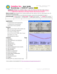
WWW.LASER2000.NL CO2mpact User Manual Beam Delivery System for sub 500W lasers 06/06/2011 Official ULO Optics distributor LASER 2000 BENELUX C.V. – Voorbancken 13A – Postbus 20 – 3645 ZJ Vinkeveen – Nederland Tel: +31-(0)297-266191–Fax: +31-(0)297-266134-Email: [email protected] – www.laser2000.nl RABO 36.96.07.139 - BTW nr. NL 807.677.814 B01 – KvK Utrecht 32073675 Page1 Introduction ........................................................................................................... 3 Laser mounts C-LM and C-LMA ........................................................................... 4 Thread inserts ....................................................................................................... 4 Beam pipe C-BPxx................................................................................................ 6 Extender pipe C-BPExx/yy.................................................................................... 6 Retractable mount C-RM ...................................................................................... 7 Pipe supports C-PS .............................................................................................. 7 Beamexpanders C-BEx.x...................................................................................... 8 Beamexpander theory ....................................................................................... 8 Manual attenuator, C-MA .....................................................................................10 Principle of operation........................................................................................10 Attenuator use ..................................................................................................14 Reflection isolator C-RI ........................................................................................15 Principle of operation........................................................................................15 Corner mirror block C-CM ....................................................................................16 Fine focus adjustment C-FA.................................................................................17 Centring cell C-CC ...............................................................................................17 Lens nozzle assemblies C-LNxx ..........................................................................18 Shutter head unit C-SU........................................................................................19 Description and use..........................................................................................19 Internal circuit ...................................................................................................19 Laser Shutter Controller LSC01 ...........................................................................20 Connections .....................................................................................................21 Operation..........................................................................................................21 Circuit Operation ..............................................................................................21 Beam injector module, C-BI .................................................................................23 Power ...............................................................................................................23 Diode Laser ......................................................................................................23 CO2 Laser Beam ..............................................................................................23 Alignment of Visible Beam ...............................................................................23 Cross wire C-CW .................................................................................................24 Thread adapters...................................................................................................25 The optics ............................................................................................................25 Focusing lenses 7.5ZLF38, 7.5ZLF63 and 7.5ZLF100.....................................25 Silicon mirrors 9.8SIS3-00 and 10SIS3-00 .......................................................26 Phase retarders 9.8SPR3-90 and 10SPR3-90 .................................................26 Silicon mirror 11SIS3-00 ..................................................................................26 Beam combiner 9.8ZBS3-45-R ........................................................................26 Brewster windows ZBW5320MP and EZBW5320MP.......................................26 Beamexpander output lens 11ZLF63 ...............................................................26 Beamexpander input lenses .............................................................................26 06/06/2011 Official ULO Optics distributor LASER 2000 BENELUX C.V. – Voorbancken 13A – Postbus 20 – 3645 ZJ Vinkeveen – Nederland Tel: +31-(0)297-266191–Fax: +31-(0)297-266134-Email: [email protected] – www.laser2000.nl RABO 36.96.07.139 - BTW nr. NL 807.677.814 B01 – KvK Utrecht 32073675 Page2 Introduction As the name suggests, CO2MPACT beam delivery is intended for small CO2 lasers, in this case, up to 500W power and with beams up to about 12mm diameter. From the laser output to the work piece, the beam delivery consists of components that enable the beam to be handled with efficiency. The parts are easily assembled with the aid of the thread inserts and the system can be firmly secured to a bench top with the pipe supports. In the following sections, each of the individual parts is described. Some require very little explanation, but others require considerably more detail in order to explain the optical function and its use. ‘Example’ of an assembled system. From top left to bottom right, laser mount, attenuator, beamexpander, pipe + pipe support, shutter, beam injector, corner mirror block, extender pipe, fine focusing unit, centring cell, lens and nozzle assembly. Some short sections of beam pipe are between the various parts. 06/06/2011 Official ULO Optics distributor LASER 2000 BENELUX C.V. – Voorbancken 13A – Postbus 20 – 3645 ZJ Vinkeveen – Nederland Tel: +31-(0)297-266191–Fax: +31-(0)297-266134-Email: [email protected] – www.laser2000.nl RABO 36.96.07.139 - BTW nr. NL 807.677.814 B01 – KvK Utrecht 32073675 Page3 This section view shows how a thread insert connects a length of pipe to a corner mirror block. Laser mounts C-LM and C-LMA http://www.ulooptics.com/docs/pdf/tdsulo_96_10.pdf Coming in two versions, these mounts allow the CO2MPACT equipment to be attached directly to the output end plate of the laser. The screw hole pattern is arranged to match your laser. The central hole is threaded to match the thread inserts (see below) from which beam pipe and other items can be attached. A small amount of clearance in the screw holes will allow some sideways movement to centre the beam to the bore. If your beam is accurately perpendicular to the laser end plate then the C-LM will suffice, however, should you need to tilt the beam delivery over slightly to follow the beam then the adjustable version C-LMA is recommended. This consists of two plates, the first being bolted to the laser and the second is adjusted for tip and tilt using the three screws. A compressed O-ring sits between the plates to provide the ‘spring’ for the adjustment. Thread inserts 06/06/2011 Official ULO Optics distributor LASER 2000 BENELUX C.V. – Voorbancken 13A – Postbus 20 – 3645 ZJ Vinkeveen – Nederland Tel: +31-(0)297-266191–Fax: +31-(0)297-266134-Email: [email protected] – www.laser2000.nl RABO 36.96.07.139 - BTW nr. NL 807.677.814 B01 – KvK Utrecht 32073675 Page4 These stainless steel thread inserts are used to couple together the various parts of the CO2MPACT range. They have a M29 x 1mm thread and an inner diameter of 19mm. Slots at each end allow some leverage to tighten against a stop and undo them again. 06/06/2011 Official ULO Optics distributor LASER 2000 BENELUX C.V. – Voorbancken 13A – Postbus 20 – 3645 ZJ Vinkeveen – Nederland Tel: +31-(0)297-266191–Fax: +31-(0)297-266134-Email: [email protected] – www.laser2000.nl RABO 36.96.07.139 - BTW nr. NL 807.677.814 B01 – KvK Utrecht 32073675 Page5 Beam pipe C-BPxx http://www.ulooptics.com/docs/pdf/tdsulo_96_04.pdf Beam pipe serves as a shroud to the laser beam so that accidental blocking of the beam cannot occur. In particular, for Health and Safety reasons, an invisible laser beam such as the CO2 beam cannot be blocked by a part of the body. Of course, beam pipe also serves to connect the other parts of the beam delivery system together, making it a more rigid structure. Yet a third reason for its use, is to contain a purge atmosphere that has a slight positive pressure. This helps to keep dust out of the beam path as well as stabilising the beam from the effects of absorbing gases. The standard lengths are 30mm, 50mm, 100mm and 300mm. Using the thread inserts, longer lengths can be created. An odd length can be made using the extender pipe. A 30mm length can also be supplied with a purge nozzle (C-BPP30). The internal bore is 19mm and connection is made to other components by the thread inserts. Extender pipe C-BPExx/yy Extender pipe is a telescopic section of beam pipe that is used to bridge a gap that does not correspond to the standard lengths of fixed length beam pipe. The extending section is a slide-and-lock mechanism. The length range covered is 50 to 70mm in one version (C-BPE50/70) and 85 to 125mm in the second (C06/06/2011 Official ULO Optics distributor LASER 2000 BENELUX C.V. – Voorbancken 13A – Postbus 20 – 3645 ZJ Vinkeveen – Nederland Tel: +31-(0)297-266191–Fax: +31-(0)297-266134-Email: [email protected] – www.laser2000.nl RABO 36.96.07.139 - BTW nr. NL 807.677.814 B01 – KvK Utrecht 32073675 Page6 BPE85/125). As with normal beam pipe, thread inserts are used to connect to other parts and the bore is the same 19mm. Retractable mount C-RM The retractable mounts are used in pairs and fixed either side of a part that you may need to remove from the system without upsetting the position of other components. Alternatively, they can be used to lock other components in a certain azimuth orientation. Attach them to the component using thread inserts and then use their coupling rings to connect to the beam pipe. The coupling rings, once unscrewed from the thread insert, are simply pulled back to allow the part to be lifted out. The beam injector and shutter units are supplied with these mounts. Pipe supports C-PS http://www.ulooptics.com/docs/pdf/tdsulo_96_04.pdf The pipe supports are to allow the beam pipe sections to be firmly clamped to a work surface at a height to match your laser. They consist of 4 parts: the base, a middle section, and a V section to hold the pipe and the clamp. The base has 2 slotted holes to allow mounting to optical tables that have a hole spacing of 25mm or 1”. The hole separation is 75mm/3”. The middle section is the piece that is chosen to bring the beam pipe up to the correct height. Common laser types catered for are those made by Rofin, Coherent, Synrad and Spectron. There is a small amount of height adjustment available by loosening 2 screws on the support’s side. Standard heights are 73, 78, 81 and 123mm. 06/06/2011 Official ULO Optics distributor LASER 2000 BENELUX C.V. – Voorbancken 13A – Postbus 20 – 3645 ZJ Vinkeveen – Nederland Tel: +31-(0)297-266191–Fax: +31-(0)297-266134-Email: [email protected] – www.laser2000.nl RABO 36.96.07.139 - BTW nr. NL 807.677.814 B01 – KvK Utrecht 32073675 Page7 Beamexpanders C-BEx.x http://www.ulooptics.com/docs/pdf/tdsulo_96_01.pdf Beamexpander theory As the name suggests, a beamexpander’s purpose is to enlarge the diameter of a laser beam. This is done for two possible reasons: 1) 2) When focused, a larger diameter beam will give a smaller spot. Thus a beam is expanded to produce higher energy densities on the target. A large beam also has a smaller divergence and does not change its diameter as much when propagating over many meters (unless deliberately defocused). In a flying-optics type system, this helps to keep the energy density at the focus constant as the optics vary their distance from the laser and also reduces the focus shift due to the wavefront curvature variation. The above two points can be expressed mathematically by the equations: S= 4 M 2 λF πD (1) 2 Where S = Focused spot diameter, F = Lens focal length, D = Beam diameter at the lens, M = Beam Msquared factor (not the magnification). Note that the focusing lens must be diffraction limited. D0θ = 4M 2 λ π (2) Where D0 = Beam waist diameter, θ = Beam far-field divergence (full angle). The right-hand side of this equation is a constant for any particular beam, so as D0 increases, θ will decrease. If a beamexpander’s magnification is ‘m’, then the input and output beams are related by the following equations: DOut = mDIn (3) 1 1 1 = + ROut m 2 RIn G (4) θ Out = θ In m (5) Where D are the beam diameters and R the wavefront radii (see Fig 1). ‘G’ is the geometric focus setting of the beamexpander. On more expensive models than the CO2MPACT, this will be the value engraved on the focus ring. Normally, however, G is set by experimentation. Note that if G is set to infinity (beamexpander 06/06/2011 Official ULO Optics distributor LASER 2000 BENELUX C.V. – Voorbancken 13A – Postbus 20 – 3645 ZJ Vinkeveen – Nederland Tel: +31-(0)297-266191–Fax: +31-(0)297-266134-Email: [email protected] – www.laser2000.nl RABO 36.96.07.139 - BTW nr. NL 807.677.814 B01 – KvK Utrecht 32073675 Page8 has zero optical power), the output wavefront radius is not equal to the input wavefront radius, unless a beam waist is located at the input (RIn = ∞). D Out R In ULO OPTICS FOCUS LOCK D In R Out Fig 1: Definition of terms The last equation (5) above relating the far-field divergence on the input and output sides, can generally be summarised by saying that all angles are reduced by m, including beam alignment errors to the optical axis. CO2MPACT beamexpanders CO2MPACT beamexpanders are optically identical to ULO Optics’s BSL12 series (BSLs now being phased out). The difference is that the CO2MPACT version has a slightly longer body and is modified to take a thread insert at the output end. The input end has a built-in thread. The slide-and-lock focus mechanism allows beam wavefront radius to be adjusted. The central position being factory set for infinity focus. However, the actual setting needed, will be determined by experimentation. The magnifications available are listed the Table 1 below along with input clear apertures. Note that the lowest and highest magnifications possible in the housing are 1.3 and 7.0 respectively. Although a longer housing is possible to cover magnifications 7 to 12. Mag Input CA(mm) 1.3 1.6 2.0 2.5 3.0 3.5 4.0 5.0 6.0 7.0 19.5 15.9 12.7 10.2 8.5 7.3 6.3 5.1 4.0 3.6 Table 1: Input clear apertures The output lens is common to all magnifications and together with the mechanical length of the slide-and-lock slot, determines the focusing range of +1 metre through infinity to –1 metre. Thus the beamexpander can be used as a ‘long working distance’ focusing lens. When used as such, however, the focal length is equal to the working distance (=G) divided by the magnification, m, i.e. F = G/m E.g. when a x7 beamexpander is adjusted to focus over 1400mm, the (effective) focal length is 1400 / 7 = 200mm, not 1400mm. You can use F = 200mm in the equation above for spot size, S, provided D is the input beam diameter (alternatively, you could use 1400mm for ‘F’ and the output beam diameter for ‘D’: both are larger by the magnification factor). Beamreducers Occasionally, someone may wish to use a beamexpander in reverse, as a beamreducer. In principle there is no reason why this cannot be done, however, there are a few cautions to bear in mind: 1) 2) 3) The power density at the output will increase with the square of magnification, m (‘m’ being the magnification of the beamexpander). The far-field divergence angle of the output beam and any angular misalignment errors of the beam, increase by the magnification, m. Centring the beam to the beamexpander will therefore be more critical and it may grow more rapidly than you expect. 2 The focusing becomes much more critical. The range will be approximately +1000/m through infinity to 2 –1000/m millimeters. Therefore some short focusing distances are possible. It is advisable when setting up the beamreducer, not to have any other optics further down the beam until the focusing is set correctly. This will prevent possible damage from having a focused beam accidentally directed onto another optical component. 06/06/2011 Official ULO Optics distributor LASER 2000 BENELUX C.V. – Voorbancken 13A – Postbus 20 – 3645 ZJ Vinkeveen – Nederland Tel: +31-(0)297-266191–Fax: +31-(0)297-266134-Email: [email protected] – www.laser2000.nl RABO 36.96.07.139 - BTW nr. NL 807.677.814 B01 – KvK Utrecht 32073675 Page9 Manual attenuator, C-MA http://www.ulooptics.com/docs/pdf/tdsulo_96_07.pdf Principle of operation The principle of operation is based on the ‘Brewster angle’. When linearly polarised light is incident on an airoptical material interface (uncoated), usually some of the light is reflected and some transmitted. However, when linearly polarised in the orientation shown in Fig 1 (known as ‘P’ polarisation), there is no reflected light; 100% is transmitted into the material, provided the angle of incidence is equal to the Brewster angle. This is not so when the polarisation is in the perpendicular direction as shown in Fig 2 (known as ‘S’ polarisation). Fig 1: P polarisation Fig 2: S polarisation If there is a mixture of polarisations then the situation is more complex, but the transmitted light will contain less of all polarisations except P. By using a series of interfaces eventually the transmitted light will be all P and some of the laser beam power is lost. Obviously, a window as 2 air/material interfaces. The value of the Brewster angle is calculated by: I Brewster = tan −1 (n ) (1) Where ‘n’ is the refractive index of the material. Table 1 lists the values for ZnSe against different wavelengths. 06/06/2011 Official ULO Optics distributor LASER 2000 BENELUX C.V. – Voorbancken 13A – Postbus 20 – 3645 ZJ Vinkeveen – Nederland Tel: +31-(0)297-266191–Fax: +31-(0)297-266134-Email: [email protected] – www.laser2000.nl RABO 36.96.07.139 - BTW nr. NL 807.677.814 B01 – KvK Utrecht 32073675 Page10 λ (µm) 0.633 3.0 7.0 10.6 12.0 n 2.591 2.438 2.422 2.403 2.393 IBrewster 68.90° 67.70° 67.57° 67.40° 67.32° TP (%) * 99.90 99.99 100 100 100 TS (%) 47.28 49.73 50.01 50.33 50.51 Table 1: ZnSe Brewster angle data (* with IBrewster set at 10.6µm value) The Brewster angle does not vary much with wavelength so the transmittance does not vary greatly once set for a particular wavelength. An attenuator based on the Brewster angle will work well over a broad range of wavelengths. (NOTE: there are versions for 10.6µm where coatings have been applied to the surface. These will not function at other wavelengths). A flat window tilted to operate at the Brewster angle of incidence is usually referred to as a Brewster plate (or window). In an attenuator, two of these are mounted in a ‘V’ arrangement as shown in Fig 3. Because of the 67.4° angle of incidence when ZnSe is used, the plates need to be 2.6 times longer than their width in order to present a square profile to the beam. The ‘V’ configuration corrects for the beam displacement. Fig 3: Arrangement in a ‘V’ configuration of 2 x ZnSe Brewster plates There are 4 air/ZnSe interfaces (2 plates) in the attenuator, each transmitting 100% TP and 50.33% TS. Consequently, after all 4 interfaces the nett transmittance is 100% TP and 6.4% TS. These values represent the limits for the transmittance of an attenuator. To vary the transmitted power the plates are rotated about the beam axis. If θ represents the angle between the direction of polarisation in the incident beam and the P plane of the Brewster plates, then the transmittance of the attenuator is given by: T = 1 − 0.9358 sin 2 (θ ) (2) Fig 4 plots the results in a graph. Transmission, T (%) Transmission, T (%) 100 100 90 90 80 80 70 70 60 60 50 50 40 40 30 30 20 20 10 10 0 0 0 0 10 10 20 30 40 50 60 70 20 30 40 50 60 70 Rotation angle of attenuator, θ (deg) Rotation angle of attenuator, θ (deg) 80 80 90 90 Fig 4: Plot of transmission against rotation angle for a pair of uncoated ZnSe Brewster plates. 06/06/2011 Official ULO Optics distributor LASER 2000 BENELUX C.V. – Voorbancken 13A – Postbus 20 – 3645 ZJ Vinkeveen – Nederland Tel: +31-(0)297-266191–Fax: +31-(0)297-266134-Email: [email protected] – www.laser2000.nl RABO 36.96.07.139 - BTW nr. NL 807.677.814 B01 – KvK Utrecht 32073675 Page11 Less known is that the output plane of polarisation is rotated with respect to the input (denoted here by φ see Fig 5). As the attenuator is rotated, the plane of polarisation is ‘dragged’ with it, but at a smaller angle. It actually reaches a maximum angle before reversing and dropping back to zero. This is due to Fig 5: Definition of angles θ and φ. the residual transmission of the S polarisation, which eventually dominates. The formula for the rotation is shown here and Fig 6 is a graph. 0.7466 sin (θ )cos (θ ) 2 1 − 0.7466 sin (θ ) φ = tan −1 (3) Rotation angle of plane of polarization, Rotation angle of plane of polarization, (deg) (deg) 40 40 35 35 30 30 25 25 20 20 15 15 10 10 5 0 5 0 0 0 10 10 20 30 40 50 60 70 20 30 40 50 60 70 Rotation angle of attenuator, θ (deg) Rotation angle of attenuator, θ (deg) 80 80 90 90 Fig 6: Rotation of polarisation for a pair of uncoated ZnSe Brewster plates. This is no problem if the process is polarisation insensitive, but where the output beam must have a fixed plane of polarisation (e.g. when the beam will subsequently be reflected off a phase retarder), then some corrective action is required to rotate the polarisation back. One way to accomplish this is by having a set of static Brewster plates afterwards. However quite a few can be needed: 6 to ensure that the plane of polarisation remains within 1° of its original direction. The number of plates can be reduced by using the coated type, although these have power handling restrictions (~ 500W). 06/06/2011 Official ULO Optics distributor LASER 2000 BENELUX C.V. – Voorbancken 13A – Postbus 20 – 3645 ZJ Vinkeveen – Nederland Tel: +31-(0)297-266191–Fax: +31-(0)297-266134-Email: [email protected] – www.laser2000.nl RABO 36.96.07.139 - BTW nr. NL 807.677.814 B01 – KvK Utrecht 32073675 Page12 Alternatively, a second attenuator rotated by an angle in the opposite direction can re-align the polarisation exactly. In both cases, the transmittance curve in fig 4 will be changed. In summary, Brewster attenuators are most useful when the laser itself has no means of power control and the process is polarisation insensitive. The polarisation must also be linear. Coated Brewster Plates By coating one surface of each plate with a special coating, it is possible to enhance the reflectance of the S polarisation to 98% (from 50%) at the expense of a slight loss to the P polarisation (99% transmission instead of ~100%). The result is that the minimum transmittance through the attenuator is now much lower at ~ 0.04%. (2% of 2%). The coating is a complex stack of layers, so the absorption limits the laser power to around 500W. However, this is the recommended limit for the CO2MPACT series anyway. The corresponding curves for Fig 4 and 6 above are shown below in 7 and 8. Note that the transmission curve closely follows Malus’s law (T = cos2θ) for a perfect linear polariser. Note also that for a perfect polariser, the plane of polarisation in the output would follow the attenuator all the way round to 90°. For the coated attenuator, however, the polarisation will still flip back to zero, but from a higher angle. Transmission, T (%) Transmission, T (%) 100 100 90 90 80 80 70 70 60 60 50 50 40 40 30 30 20 20 10 10 0 0 0 0 10 10 20 30 40 50 60 70 20 30 40 50 60 70 Rotation angle of attenuator, θ (deg) Rotation angle of attenuator, θ (deg) 80 80 90 90 Fig 7: Plot of transmission against rotation angle for a pair of coated ZnSe Brewster plates. 06/06/2011 Official ULO Optics distributor LASER 2000 BENELUX C.V. – Voorbancken 13A – Postbus 20 – 3645 ZJ Vinkeveen – Nederland Tel: +31-(0)297-266191–Fax: +31-(0)297-266134-Email: [email protected] – www.laser2000.nl RABO 36.96.07.139 - BTW nr. NL 807.677.814 B01 – KvK Utrecht 32073675 Page13 Rotation angle of plane of polarization, Rotation angle of plane of polarization, (deg) (deg) 80 80 70 70 60 60 50 50 40 40 30 30 20 20 10 10 0 0 0 0 10 10 20 30 40 50 60 70 20 30 40 50 60 70 Rotation angle of attenuator, θ (deg) Rotation angle of attenuator, θ (deg) 80 80 90 90 Fig 8: Rotation of polarisation for a pair of coated ZnSe Brewster plates. Attenuator use The attenuator has a graduated ring with lock screw. Turning this ring rotates the Brewster plates inside and the scale reads the nominal transmission (some later versions may have some extra numbers relating to the transmission with coated plates). With the ring set to ‘100’ (%), note that the P plane of the Brewster plates align with the large arrow at the opposite end of the barrel. This arrow also shows the preferred direction of laser beam travel (more relevant for the coated plate version). With the ring locked in the 100 position, mount the attenuator in the system and rotate the whole body until the large arrow lies in the known plane of polarisation. The P plane of the Brewster plates will then coincide with plane of polarisation and the transmission will be at a maximum (~100%). For a more accurate set up, monitor the laser power through the attenuator and adjust for the maximum power reading. In most lasers the plane of polarisation is either vertical or at 45° to the vertical, meaning that the arrow will either be uppermost or 45° to one side. Finally, lock the attenuator to its supports both ends. Turning the graduated ring will now vary the transmitted power, dumping the rest inside the body. For prolonged periods of dumping power and for higher powers, the body will get hot. Fitting the water-cooled jacket will then be advisable. 06/06/2011 Official ULO Optics distributor LASER 2000 BENELUX C.V. – Voorbancken 13A – Postbus 20 – 3645 ZJ Vinkeveen – Nederland Tel: +31-(0)297-266191–Fax: +31-(0)297-266134-Email: [email protected] – www.laser2000.nl RABO 36.96.07.139 - BTW nr. NL 807.677.814 B01 – KvK Utrecht 32073675 Page14 Reflection isolator C-RI http://www.ulooptics.com/docs/pdf/tdsulo_96_08.pdf Principle of operation Optically the reflection isolator is identical to the manual attenuator, but is not intended to allow the out-going beam power to be varied. It is installed in the system to allow the out-going beam to pass without loss. However, any beam travelling back towards the laser and polarised in the orthogonal direction will be attenuated. Using two uncoated Brewster plates the transmittance will be 6.4% and two coated plates, about 0.04%. In some laser systems this function is useful to prevent a beam reflection from the work piece travelling all the way back into the laser cavity where it can cause instability to the power or damage in a high power laser. The laser user will need to consult the laser manufacturer to estimate what power level can be tolerated by the cavity and hence whether coated or uncoated plates are necessary (or even more than one isolator in series). Fig 1: Set up required for the reflection isolator As mentioned above, the backward reflection must be polarised orthogonal to the out-going beam, so somewhere in the system between the isolator and work piece, the polarisation must be rotated through 90° in order for the isolator to work. This will happen in a system where a λ/4 (1/4-wave or 90°) phase retarder mirror is used to convert the linearly polarised beam into a circularly polarised one. Such an arrangement is 06/06/2011 Official ULO Optics distributor LASER 2000 BENELUX C.V. – Voorbancken 13A – Postbus 20 – 3645 ZJ Vinkeveen – Nederland Tel: +31-(0)297-266191–Fax: +31-(0)297-266134-Email: [email protected] – www.laser2000.nl RABO 36.96.07.139 - BTW nr. NL 807.677.814 B01 – KvK Utrecht 32073675 Page15 common and is widely used for metal processing. The metals Aluminium and Copper are particularly noted for sending back an unwanted reflection towards the laser. Fig 1 shows the arrangement that is required. The out-going beam is polarised for maximum transmission through the isolator and 45° to the S and P directions for the phase retarder mirror. After reflection the beam is circularly polarised and is used in this state to process the material. If a backward reflection occurs, it is reflected off the phase retarder a second time and undergoes another λ/4 phase retardation. This second reflection does not ‘undo’ the first to give a zero retardation but adds to it to give a λ/2 (or 180°) retardation. The result is to re-create linear polarisation but orthogonal to the out-going beam. Therefore the isolator will dump the beam. Note that inaccuracies in the phase retarder coating and alignment of the polarisation to the mirror will result in elliptical polarisation in the reflected beam, with a less efficient dumping of the power in the isolator. Reflection isolator use The isolator is installed in the same way as the attenuator, except there is no ring to adjust the power. The arrow on the barrel defines the P plane of the Brewster plates and the preferred direction of propagation (more relevant for the coated plate version). Rotate the isolator in the beam until this arrow is aligned to the direction of polarisation or using a power meter, gives the maximum transmittance. Then lock in place. Corner mirror block C-CM http://www.ulooptics.com/docs/pdf/tdsulo_96_02.pdf The C-CM corner mirror block uses 25.4mm (1”) or 25mm diameter Silicon mirrors coated with the Supermax coating. As an alternative though, a λ/4 phase retarder may be used. The mirror is mounted in a ring that has tip and tilt adjustments, which are accessible through two holes in the cover plate. The latter holds a conical spring that bears on the mirror back to provide some restraining force. Mirror blocks will be supplied pre-aligned to within a few arc minutes, so should not need much adjustment. If large amounts of adjustment are actually required (about +/-2° are available), then check the alignment of the incident beam and whether previous components are correct. The mirror can be changed without affecting the alignment. To do this undo the two screws that hold the cover plate in place and remove, together with the spring. Pull on the edge of the mirror to remove (or use a piece of tape stuck to the mirror back). Replace with the new mirror and screw the cover plate on with the spring in place. Note that the large coil of the spring fits into the recess inside the cover plate. The mirror blocks accept the thread insert or retractable mounts. One of the latter on the input side is recommended as this allows the mirror block to be orientated in azimuth to any angle (useful when the corner mirror block contains a phase retarder). Note that the clear aperture on the C-CM is 16.4mm. 06/06/2011 Official ULO Optics distributor LASER 2000 BENELUX C.V. – Voorbancken 13A – Postbus 20 – 3645 ZJ Vinkeveen – Nederland Tel: +31-(0)297-266191–Fax: +31-(0)297-266134-Email: [email protected] – www.laser2000.nl RABO 36.96.07.139 - BTW nr. NL 807.677.814 B01 – KvK Utrecht 32073675 Page16 Fine focus adjustment C-FA http://www.ulooptics.com/docs/pdf/tdsulo_96_05.pdf This adjustable component is intended as a manual focusing device for a lens and nozzle assembly. By turning the notched ring, the tube with the engraved scale lowers or raises at a rate of 1mm per turn. 0.1mm increments are engraved on the outer sleeve. In total there is 20mm of movement, engraved as 10-5-0-5-10 with 1mm lines. A locking knob is provided to secure the focus setting. The tube does not rotate as it slides: a pin at 90° to the locking knob rides in a slot to prevent rotation. This in turn prevents any beam wander from residual lens centring errors. Both ends of the focusing unit have the thread to take the thread inserts. Centring cell C-CC The centring cell has the two ‘thread insert’ connections on each side; one for the input and one for the output. By adjusting the 3 screws in the body side, it is possible to laterally adjust one with respect to the other, either to precisely align the output to the beam or to introduce a deliberate offset. Note that the screws need to be loosened on one side before those opposite can be screwed inwards. All 3 screws must be tightened once the adjustment is made. 06/06/2011 Official ULO Optics distributor LASER 2000 BENELUX C.V. – Voorbancken 13A – Postbus 20 – 3645 ZJ Vinkeveen – Nederland Tel: +31-(0)297-266191–Fax: +31-(0)297-266134-Email: [email protected] – www.laser2000.nl RABO 36.96.07.139 - BTW nr. NL 807.677.814 B01 – KvK Utrecht 32073675 Page17 Lens nozzle assemblies C-LNxx http://www.ulooptics.com/docs/pdf/tdsulo_96_06.pdf The lens and nozzle assemblies come for 3 standard lens focal lengths: 38, 63 and 100mm. The lenses are mounted in a separate cell that is screwed into the nozzle section. The C-LN100 is a C-LN63 plus an extension piece and is shown above. The clear aperture inside the lens assembly is 17.5mm. The copper nozzle is removed by unscrewing the cap while to adjust it’s distance from the lens (to give the correct stand-off, +/-3mm), unscrew the lock ring and screw the threaded tube in or out. Then tighten the lock ring. The gas nozzle inlet allows a gas purge to be directed through the nozzle. With the standard lens, a pressure of up to 5 bar is possible. The inlet requires 6/4 tubing. 06/06/2011 Official ULO Optics distributor LASER 2000 BENELUX C.V. – Voorbancken 13A – Postbus 20 – 3645 ZJ Vinkeveen – Nederland Tel: +31-(0)297-266191–Fax: +31-(0)297-266134-Email: [email protected] – www.laser2000.nl RABO 36.96.07.139 - BTW nr. NL 807.677.814 B01 – KvK Utrecht 32073675 Page18 Shutter head unit C-SU http://www.ulooptics.com/docs/pdf/tdsulo_96_09.pdf Description and use The shutter head uses a rotary solenoid to flip a Supermax coated Silicon mirror in and out of the beam. When the shutter is closed, the beam is reflected onto a water-cooled beam dump. When open, the beam passes straight through the unit. The open position is the electrically activated state of the solenoid. Therefore, if the power were to fail, the shutter will close (a spring provides the force). LEDs on the shutter head indicate the status: red for open and green for closed. The open and close positions are detected by opto-reflective switches. Power is provided via the 9-pin D connector and open/close status can also be monitored via this connector. An optional Laser Shutter Controller, LSC01, supplies power and monitors the status of the shutter. Note that the shutter is intended as a safety shutter and not for brief timing exposures. Using the LSC01, typical opening and closing times have been measured at 30 and 60 msec respectively (as defined by the period in which neither limit switch ‘sees’ the mirror). Note that these times cannot be equalised due to the solenoid limitations. The clear aperture is 19mm. The beam dump is water cooled via the connectors (6/4 M6). For a water temperature rise of ∆T °C and a laser power P Watts, the water flow rate should be 0.014P/∆T litres/min. e.g. for a 10° rise in water temperature and 500W, the flow is 0.7 litres/min. The shutter heads are provided with retractable screw rings for mounting to beam pipe. Before installing the shutter, check that the beam is centred to the beam pipe. Also note that there is an input and output side. Sending the beam in from the wrong side will cause it to hit the rear of the mirror mount. The shutter will operate in any orientation. Internal circuit For those who wish to provide their own controller, the drawing below shows the internal circuit of the shutter head. Note that only 5 pins on the connector are actually used. Any controller must supply +12V to pin 1 and be able to provide up to 1A. To open the shutter, pin 3 is taken to 0V. This can be done via a simple switch or using a transistor. The reflective opto-switches OPB704 detect the presence of the mirror. When the internal transistor sees light from the diode reflected off the mirror, it conducts, pulling the base of the 2N3904 up and causing it to conduct. The latter acts as a current booster to supply the indicator LED and pass the signal for external use via pins 7 and 8 (going high to denote detection). The reverse biased diode 1N4007 suppresses any back emf when the solenoid is deactivated. 06/06/2011 Official ULO Optics distributor LASER 2000 BENELUX C.V. – Voorbancken 13A – Postbus 20 – 3645 ZJ Vinkeveen – Nederland Tel: +31-(0)297-266191–Fax: +31-(0)297-266134-Email: [email protected] – www.laser2000.nl RABO 36.96.07.139 - BTW nr. NL 807.677.814 B01 – KvK Utrecht 32073675 Page19 D connector, 9 way, pins (473-880) 1 +12V 2 4 5 6 O PB704 (307-913) 8 O PB704 (307-913) 7 4 9 5 3 10 'Open' signal 'Closed' signal 6 1 2N3904 (294-312) 10k (148-736) 2N3904 (294-312) 1 2 3 4 5 10k (148-736) 'O pen' 'Closed' Red (228-5988) Rotary solenoid, 35mm, 45deg (343-313) G reen (228-6004) 6 7 8 9 1N4007 (348-5397) 390R (163-533) 390R (163-533) 390R (163-533) 390R (163-533) 2 3 8 9 Solenoid return 0V PCB + 10 way r/a 1.25mm connector (279-9320) + 10 way housing (279-9207) Fig 1: Internal circuit of C-SU head Laser Shutter Controller LSC01 Fig. 1: Front and rear panels 06/06/2011 Official ULO Optics distributor LASER 2000 BENELUX C.V. – Voorbancken 13A – Postbus 20 – 3645 ZJ Vinkeveen – Nederland Tel: +31-(0)297-266191–Fax: +31-(0)297-266134-Email: [email protected] – www.laser2000.nl RABO 36.96.07.139 - BTW nr. NL 807.677.814 B01 – KvK Utrecht 32073675 Page20 Connections The LSC01 is supplied with two cables: a mains cable and one to connect to the shutter head terminated in the D type plugs. The controller is powered from an 85V – 260V ac supply connected to the rear panel IEC receptacle. The shutter is connected, using the cable supplied, to the rear panel 9-pin “D” socket labelled SHUTTER. If required, the shutter can be controlled and monitored remotely via the other 9-pin “D” plug labelled PC. Operation The front panel push button switches the controller mains power on or off. It is illuminated when powered on. Before switching on, check that the toggle switch is in the closed position or if being controlled from a PC, that a ‘close’ signal is being sent. This will ensure that the shutter does not open unexpectedly on power-up. The toggle switch opens or closes the shutter. The left position will open the shutter and the right position will close the shutter. Note that if the controller is switched off at the mains, the shutter will default to the closed position. The red OPEN indicator will light when the shutter is open. The green CLOSED indicator will light when the shutter is closed. (Note: Other ULO Optics shutters ‘ESU’ types have a manually operated lock that allows the shutter to be locked in the closed position only. The yellow LOCKED indicator will light to indicate this. The CO2MPACT shutter C-SU does not have a lock, so the yellow LED is inactive). The status of the shutter can also be monitored via the rear panel 9-pin PC connector. Opto-isolators are used to give a grounded signal to indicate open, closed or locked and a high impedance for the inverse. The shutter can be opened by applying 5V to the shutter enable pin 3 relative to GND. Note that to operate the shutter from a computer, set the toggle switch to the CLOSED position. Fig 1: D connector pins on rear of LSC01 PC 1 2 6 PC pin 1 2 3 4 5 6 7 8 9 3 7 4 8 5 5 9 no connection no connection Shutter enable (+5V open, 0V close) no connection no connection Locked (GND = locked, high Z = unlocked Closed (GND = closed, high Z = not closed Open (GND = open, high Z = not open GND SHUTTER 4 3 2 1 RR 9 8 7 6 SHUTTER pin 1 +12V 2 no connection 3 Shutter enable 4 5 6 7 8 9 no connection no connection Locked (+12V = locked) Closed (+12V = closed) Open (+12V = open) GND Circuit Operation The shutter solenoid is connected between connector SHUTTER pin 1 (+12V) and pin 3 (TR1 drain). When switch SW is switched to CLOSE, the gate of TR1 is pulled low by R2 and so TR1 is switched off. Therefore no power is applied to the solenoid and the shutter assumes the default-closed position. When SW is switched to OPEN, TR1 gate is pulled up to +12V and TR1 is turned on. This provides a current path from +12V through the solenoid to 0v, and so the solenoid energises and the shutter opens. The shutter status switches are connected between +12V and connector SHUTTER pins 6, 7 and 8. When the OPEN status switch closes, it connects R1 to +12V so that LED1 lights and current flows through the emitter of the opto-isolator, IC1 causing the output transistor to turn on. Operation of the CLOSED state is similar. Note that the ‘Locked’ function and LED3 are not relevant to the C-SU. 06/06/2011 Official ULO Optics distributor LASER 2000 BENELUX C.V. – Voorbancken 13A – Postbus 20 – 3645 ZJ Vinkeveen – Nederland Tel: +31-(0)297-266191–Fax: +31-(0)297-266134-Email: [email protected] – www.laser2000.nl RABO 36.96.07.139 - BTW nr. NL 807.677.814 B01 – KvK Utrecht 32073675 Page21 If SW is in the CLOSE position, then the shutter can be controlled via connector PC. If PC pin 3 has +5V applied with respect to pin 9, then current passes through fourth opto-isolator IC1 emitter and IC1 transistor is turned on. This will pull up the gate of TR1 and so turn it on. The solenoid will be energised and the shutter will open. PC SHU TTER 0V 9 9 R ed 'Open' 0V TLP521-4 'Open' sig nal 680R 8 8 R1 'Closed' sig nal ' Locked' sig nal Solenoid return IC1 7 7 Green 'Closed' 6 5 4 680R 3 R6 6 ' Closed' detect ' Locked' detect 5 4 3 LED2 2 + 12V ' Open' detect LED1 ' Open/Close' control (+5V / 0V) 2 1 1 Yellow ' Locked' 680R R5 IRL1520 D TR1 OPEN /C LOSE SW 1K G R3 LED3 +12V 10uF C1 + 12V 390R S R2 R4 10K Fig 2: Internal circuit of LSC01 controller Note that if you wish to control the shutter using a higher voltage than 5V, then you need to add an external resistor in series with R4 (390R). The value should be, R = 80Vcontrol – 390 Ω and its power rating > R/6400 W. Also note there are no pull-up resistors to the status pins. They have been left as open collector, so that the user can select the correct value according to their supply and desired signal. 06/06/2011 Official ULO Optics distributor LASER 2000 BENELUX C.V. – Voorbancken 13A – Postbus 20 – 3645 ZJ Vinkeveen – Nederland Tel: +31-(0)297-266191–Fax: +31-(0)297-266134-Email: [email protected] – www.laser2000.nl RABO 36.96.07.139 - BTW nr. NL 807.677.814 B01 – KvK Utrecht 32073675 Page22 Beam injector module, C-BI http://www.ulooptics.com/docs/pdf/tdsulo_96_03.pdf This module allows a visible red laser beam to be aligned with the invisible infrared beam. This serves to act as an alignment aid further down the beam and as a reminder that the infrared beam is also present. Power +6V (& 30mA) is required at the jack connector to switch the laser on and light the LED indicator on the side. The power supply supplied for this purpose is voltage switchable but should be set to the 6V option. Diode Laser Inside the C-BI is a visible (red, 650nm) laser of 0.8mW power. As is usual for this type of device DO NOT STARE INTO THE BEAM DIRECTLY AND ENSURE THAT YOUR EYES AVOID ANY REFLECTED BEAMS. CO2 Laser Beam This is to be directed into the input aperture. Make sure the beam is aligned to the centre of the beam pipe before installing the C-BI. The CO2 beam will pass through the ZnSe beam combining optic and emerge at the output aperture together with the visible laser beam. Note that the clear aperture of this unit is 14.5mm. IF YOU SEND THE CO2 LASER BEAM INTO THE WRONG APERTURE, A SMALL % OF THE POWER IS REFLECTED UP TO THE DIODE LASER AND IT’S COLLIMATING LENS. DEPENDING ON THE POWERS INVOLVED, THIS COULD DAMAGE THE DIODE LASER. Alignment of Visible Beam Before coupling to the beam pipe stick a piece of masking tape over the output aperture to check that the beam is more or less central. Turn the CO2 beam off. Mount the C-BI in the system and install a target or cross-wire further down the system. Use an Allen key to adjust the tip and tilt screws A and B until the visible beam is central. Do not press down on these screws otherwise you will compress the springs that you are trying to adjust. Look for a clean beam. Any spurious flares or arcs will indicate that the tilt is so far out that the beam is reflecting off the inside of the beam pipe. Next either remove the C-BI or retract the beam pipe at the output side. Again place a piece of masking tape over the aperture. Adjust the two screws X and Y to centralise the beam. There is a few mm of movement available and the total area covered is circular. 06/06/2011 Official ULO Optics distributor LASER 2000 BENELUX C.V. – Voorbancken 13A – Postbus 20 – 3645 ZJ Vinkeveen – Nederland Tel: +31-(0)297-266191–Fax: +31-(0)297-266134-Email: [email protected] – www.laser2000.nl RABO 36.96.07.139 - BTW nr. NL 807.677.814 B01 – KvK Utrecht 32073675 Page23 When X and Y come loose while unscrewing or go tight while screwing in, the laser mount inside has reached the limit. The alignment process is iterative; adjust A and B to centralise the beam in the ‘far field’ and adjust X and Y for the ‘near field’. Finally, you may wish to make some fine adjustments with the CO2 beam on. Cross wire C-CW This useful item allows you to align the laser beam. It is a thread insert with a pair of copper wires and can therefore be screwed in at any location between parts to check for a central beam. Once the beam is aligned, replace it with a normal thread insert. A quick beam burn on card or viewing the beam on a mode plate will show the silhouette of the wires. Make adjustments until the silhouette cross is central to the beam. You need to check the alignment a various places, working your way from the laser to the work piece. Any odd mode pattern may indicate that the beam is reflecting off the inside of a pipe or is being clipped somewhere. Fig 1: Aligned (left) and mis-aligned (right) beam burns 06/06/2011 Official ULO Optics distributor LASER 2000 BENELUX C.V. – Voorbancken 13A – Postbus 20 – 3645 ZJ Vinkeveen – Nederland Tel: +31-(0)297-266191–Fax: +31-(0)297-266134-Email: [email protected] – www.laser2000.nl RABO 36.96.07.139 - BTW nr. NL 807.677.814 B01 – KvK Utrecht 32073675 Page24 Thread adapters Should the need arise where you wish to couple other beam delivery equipment to the CO2mpact range, these 4 adapters should help. They have the M29 x 1mm thread and a ¾-32UN thread in the male and female combinations. The optics The list of optics used in the CO2mpact beam delivery is as follows: Focusing lenses 7.5ZLF38, 7.5ZLF63 and 7.5ZLF100 These 3 lenses are used in the C-LN nozzle assemblies. They are all 19mm diameter and have an edge thickness of 2.0mm. When mounted in a nozzle assembly the clear aperture will be 17.5mm. The effective focal length (EFL), back focal length (BFL) and flange focal length (FFL) are as follows (see Fig 1): Lens EFL BFL FFL 7.5ZLF38 37.9mm 36.0mm 35.5mm 7.5ZLF63 65.3mm 61.8mm 61.4mm 7.5ZLF100 100.0mm 98.4mm 98.3mm EFL FFL BFL 06/06/2011 Official ULO Optics distributor LASER 2000 BENELUX C.V. – Voorbancken 13A – Postbus 20 – 3645 ZJ Vinkeveen – Nederland Tel: +31-(0)297-266191–Fax: +31-(0)297-266134-Email: [email protected] – www.laser2000.nl RABO 36.96.07.139 - BTW nr. NL 807.677.814 B01 – KvK Utrecht 32073675 Page25 Fig 1: Definition of EFL, BFL and FFL All the lenses are made from laser grade CVD ZnSe, to the optimum meniscus form for focusing purposes and each surface is anti-reflection (AR) coated for 10.6µm. Silicon mirrors 9.8SIS3-00 and 10SIS3-00 Made from monocrystalline mirror grade Silicon, these mirrors are fitted into the C-CM corner mirror blocks. The mirror block will take either size, 25 or 25.4mm diameter. They are coated with ULO’s Supermax coating, giving 99.85% reflectance at 10.6µm and 45° incidence. The mirrors also are of ‘zero phase’ type. Phase retarders 9.8SPR3-90 and 10SPR3-90 These differ from the above Silicon mirrors in the coating. The SPR type is designed to convert the linearly polarised laser beam into circular polarisation by means of a 90° phase shift difference (retardance) between the S and P components. This has processing benefits for some materials (e.g. metals). They fit into the C-CM corner mirror blocks. The mirror block itself has to be orientated with respect to the plane of polarisation as illustrated below. A retractable mount (C-RM) may therefore be needed on the input side. Silicon mirror 11SIS3-00 This Supermax coated mirror is 28mm diameter (1.1”) and is used only in the C-SU shutter unit. With the shutter closed, it reflects the beam into a water-cooled beam dump. Beam combiner 9.8ZBS3-45-R This optic finds use in the C-BI beam injector unit. Angled at 45° incidence, the CO2 laser beam will be transmitted while the red visible laser strongly reflected off one surface. Brewster windows ZBW5320MP and EZBW5320MP Brewster windows for use in attenuators and reflection isolators are made as ‘matched pairs’. A Brewster window works best if it has a slight wedge (1’ – 3’). However, this wedge deviates the beam going through it. But by using an identical second window with the wedge orientated opposite to the first, the angular beam deviation is corrected. The beam lateral displacement is also corrected because both windows have the same thickness. The windows are 53 x 20 x 3mm. Angled at 67.4° to the incident beam, they present a 20mm square profile. Beamexpander output lens 11ZLF63 For all C-BE magnifications, this is the common output lens. It is a standard lens and is used extensively for other applications. Beamexpander input lenses There is a different input lens for each magnification. Each is shaped to correct the spherical aberration of the output lens. 06/06/2011 Official ULO Optics distributor LASER 2000 BENELUX C.V. – Voorbancken 13A – Postbus 20 – 3645 ZJ Vinkeveen – Nederland Tel: +31-(0)297-266191–Fax: +31-(0)297-266134-Email: [email protected] – www.laser2000.nl RABO 36.96.07.139 - BTW nr. NL 807.677.814 B01 – KvK Utrecht 32073675 Page26 Request a Quotation Requesting a quotation is easy. Simply identify the components you need and fax this form back to us +31 297266 134. Contact Details Name Company Country Tel Fax Email Your Laser Laser Manufacturer Laser Power (W) Laser Model Optical Axis Height (mm) Beam Pipes Pipe Description Part Number 30mm long C-BP30 100mm long C-BP100 300mm long C-BP300 Adjustable 85-125mm long C-BP85/125 Qty Beam Supports Beam Support Description Part Number 73mm high C-PS73 78mm high C-PS78 81mm high C-PS81 123mm high C-PS123 Other (please specify…) _____mm high C-PSXXX Qty Qty Retractable Mount C-RM Qty Corner Mirror C-CM 06/06/2011 Official ULO Optics distributor LASER 2000 BENELUX C.V. – Voorbancken 13A – Postbus 20 – 3645 ZJ Vinkeveen – Nederland Tel: +31-(0)297-266191–Fax: +31-(0)297-266134-Email: [email protected] – www.laser2000.nl RABO 36.96.07.139 - BTW nr. NL 807.677.814 B01 – KvK Utrecht 32073675 Page27 Beam Expanders Beam Expander Description Part Number 1.3 magnification C-BE1.3 1.6 magnification C-BE1.6 2.0 magnification C-BE2.0 2.5 magnification C-BE2.5 3.0 magnification C-BE3.0 3.5 magnification C-BE3.5 4.0 magnification C-BE4.0 5.0 magnification C-BE5.0 6.0 magnification C-BE6.0 7.0 magnification C-BE7.0 Other (please specify…) _____mm high C-BEX.X Qty Qty Reflection Isolator C-RI Qty Manual Attenuator C-MA Qty Shutter Unit C-SU Beam Injector Module C-BI Fine Focus Unit C-FFA Qty Qty Lens Nozzle Assemblies Lens Nozzle Description Part Number 38mm FL (lens with nozzle) C-LN38 63mm FL (lens with nozzle) C-LN63 100mm FL (lens with nozzle) C-LN100 Qty For further information or to discuss your requirements with a member of our sales team, please contact Laser 2000 Benelux +31 297 266 191 or [email protected]. Datasheets for every component of the CO2mpact system can be downloaded from the CO2mpact website at www.co2mpact.ulooptics.com 06/06/2011 Official ULO Optics distributor LASER 2000 BENELUX C.V. – Voorbancken 13A – Postbus 20 – 3645 ZJ Vinkeveen – Nederland Tel: +31-(0)297-266191–Fax: +31-(0)297-266134-Email: [email protected] – www.laser2000.nl RABO 36.96.07.139 - BTW nr. NL 807.677.814 B01 – KvK Utrecht 32073675 Page28