1
MODEL 2400R PLOTTER
USER'S MANUAL
ATLANTEK®
Manual No. 753014 Rev 5
COPYRIGHT © 1998 by ATLANTEK INC.
Notice
The information contained in this document is subject to change without notice.
Atlantek makes no warranty of any kind with regard to this material, including, but not
limited to, the implied warranties of merchantability and fitness for a particular
purpose. No patent liability is assumed with respect to the use of the information
contained herein.
Atlantek shall not be liable for errors contained herein or for incidental or consequential
damages in connection with the furnishing, performance or use of this material.
All rights reserved. No part of this document may be photocopied, reproduced or
translated to another language without the prior written consent of Atlantek Inc.
Model 2400R-A User's Manual
Atlantek Publication No: 753014 Rev 5
Printing History:
Rev 0
Rev 1
Rev 2
Rev 3
Rev 4
Rev 5
February 1993
7 February 1996
13 March 1996
February 1997
May 1997
27 April 1998
COPYRIGHT © 1998 by ATLANTEK INC.
10 High Street, Wakefield, RI, 02879 USA
Doc't No.: MAN24L_5.DOC
Page iii
Regulatory Notices
This device complies with Part 15 of the FCC Rules. Operation is subject to the
following two conditions: (1) this device may not cause harmful interference, and (2)
this device must accept any interference received, including interference that may cause
undesired operation.
Warning: Changes or modification to this unit not expressly approved by the party
responsible for compliance could void the user's authority to operate the equipment.
Note: This equipment has been tested and found to comply with the limits for a Class
A digital device, pursuant to Part 15 of the FCC Rules. These limits are designed to
provide reasonable protection against harmful interference when the equipment is
operated in a commercial environment. This equipment generates, uses, and can
radiate radio frequency energy and, if not installed and used in accordance with the
instruction manual, may cause harmful interference to radio communications.
Operation of this equipment in a residential area is likely to cause harmful interference
in which case the user will be required to correct the interference at his own expense.
Shielded cables must be used with this unit to ensure compliance with the Class A FCC
limits.
This equipment has been designed to meet or exceed the requirements of the UL 1950
safety specification.
Acknowledgments
"Versatec" is a trademark of Xerox Inc.
"Wetordry" is a trademark of 3M Inc.
References
Versatec™, Electrostatic Printer/Plotter Interface Specifications, Bulletin No. 312,
September 1977
Versatec™, V-80 Series Electrostatic Printer/Plotter Specifications, Bulletin No. 470,
December 1979
Page iv
Warranty
Atlantek, Inc. warrants its products to be free of defects in material and workmanship under
normal use conditions for a period of one (1) year commencing the date of shipment from its
factory. Given notice and upon confirmation of such defects, Atlantek will, at its option,
either repair or replace the defective product.
Exclusions
This warranty does not apply to defects resulting from: improper or inadequate maintenance by
customer; misuse, abuse, alteration; unauthorized or improper service; operation outside the
specified environmental range; improper shipping or installation; and use of unqualified
media. This warranty does not apply to normal wear items such as friction pads, belts, and
platen.
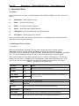
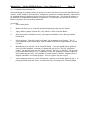
The thermal printhead is warranted for a period of one (1) year with prorated replacement
based upon the actual percentage of normalized printhead life utilized. The printhead carries a
normalized life of 50 kilometers (31 miles, approx.) of media passed under the printhead.
When reporting a printhead failure, the customer must provide the "Line Count" and "Dot
Count" readings from the plotter display. Procedure for reading these counts is described in
this manual (see Section 8.7). Prorated printhead replacement during the original warranty is
based upon the following schedule:
Distance run -- based upon displayed Line
Count:
0 to 24.9 km
25.0 to 49.9 km
50.0 to 74.9 km
75.0 km or more
Allowance for defective printhead:
100%
75%
30%
no allowance
The above warranty shall not apply to the thermal printhead used in the plotter when the
thermal printhead has been judged to have been damaged by improper cleaning, or operated
with improperly dried media.
Warranty Limitations
Atlantek makes no other warranty, either expressed or implied, with respect to this product.
Atlantek specifically disclaims the implied warranties of merchantability and fitness for a
particular purpose. Atlantek will not be liable for any special, indirect, incidental or
consequential damages or loss, including loss of data from failure of the product. Some states
or provinces do not allow limitations on the duration of an implied warranty, so the above
limitations may not apply to you. However, any implied warranty of merchantability or fitness
is limited to the one year duration of this written warranty.
Page v
Claims procedure
If an Atlantek plotter should fail, follow the instructions in the Troubleshooting section within
this manual. If you are unable to solve or determine the cause of the problem contact the
Atlantek service department at (401) 783-5700. You should have the plotters model and serial
numbers available when you call, also the processor and controller PCB’s revision level maybe
needed. The revision levels are listed on the inspection form sent with the unit or can be
determined via the front panel by referring to Section 8 and 8.2 of this manual. If we cannot
solve the problem we will provide a return authorization (RA) number. Under this RA# the
nature of the reported problem is documented, and Atlantek authorizes receipt of the incoming
defective plotter. This RA# must be prominently noted with the product returned for service.
The defective product is to be shipped freight-prepaid to Atlantek's address (given below).
Atlantek will repair or replace the defect within 30 days and return it freight-prepaid to the
customer for in warranty repairs only. The customer shall pay all shipping charges, duties and
taxes for a plotter returned from another country. Warranty repair service is provided only to
the original purchaser. If the plotter has been leased or purchased through a third party, contact
the lessor or third party for servicing.
If a defective part or subassembly is returned for repair or replacement, the same RA#
procedure is followed. The defective part or assembly is returned freight-prepaid to Atlantek.
Atlantek will repair or replace the item within 2 days and return it freight-prepaid to the
customer. To minimize time out of service, the customer may elect to order the part or
assembly with a purchase order. Atlantek will ship and invoice for the part or assembly, and
will issue credit to the customer upon receipt and confirmation of the defective part fault at its
factory.
Telephone and freight address information for Atlantek, Inc. is as follows:
Atlantek, Inc.
10 High Street, Wakefield, RI 02879 USA
Tel: (401) 783-5700, Fax: (401) 783-9881
Claims for shipping damage must be made by the customer to the carrier. The customer
should thoroughly inspect the product immediately upon original delivery and, if damaged in
any way, should file a claim with the carrier. Atlantek will upon request provide a quote to
repair shipping damage.
Page vi
Table of Contents
Regulatory Notices . . . . . . . . . . . . . . . . . . . . . . . . . . . . . . . . . . . . . . . . . . . . . . . . Page iii
Acknowledgments . . . . . . . . . . . . . . . . . . . . . . . . . . . . . . . . . . . . . . . . . . . . . . . . . Page iii
References . . . . . . . . . . . . . . . . . . . . . . . . . . . . . . . . . . . . . . . . . . . . . . . . . . . . . . Page iii
Warranty . . . . . . . . . . . . . . . . . . . . . . . . . . . . . . . . . . . . . . . . . . . . . . . . . . . . . . . Page iv
1. Introduction . . . . . . . . . . . . . . . . . . . . . . . . . . . . . . . . . . . . . . . . . . . . . . . . . . . . Page 1
2. Specifications . . . . . . . . . . . . . . . . . . . . . . . . . . . . . . . . . . . . . . . . . . . . . . . . . . . Page 4
3. Installation . . . . . . . . . . . . . . . . . . . . . . . . . . . . . . . . . . . . . . . . . . . . . . . . . . . .
3.1 Receiving Inspection . . . . . . . . . . . . . . . . . . . . . . . . . . . . . . . . . . . . . . . . .
3.2 Line Power Input Requirements . . . . . . . . . . . . . . . . . . . . . . . . . . . . . . . . . .
3.3 Line Voltage Selection . . . . . . . . . . . . . . . . . . . . . . . . . . . . . . . . . . . . . . .
3.4 Data Interface Configuration . . . . . . . . . . . . . . . . . . . . . . . . . . . . . . . . . . . .
Page 5
Page 5
Page 6
Page 6
Page 6
4. Basic Operation and Controls . . . . . . . . . . . . . . . . . . . . . . . . . . . . . . . . . . . . . . . . Page 8
4.1 Printhead Lift Mechanism . . . . . . . . . . . . . . . . . . . . . . . . . . . . . . . . . . . . . Page 8
4.2 Loading Media . . . . . . . . . . . . . . . . . . . . . . . . . . . . . . . . . . . . . . . . . . . . Page 8
4.3 Printhead Cleaning . . . . . . . . . . . . . . . . . . . . . . . . . . . . . . . . . . . . . . . . . . Page 9
4.4 Front Panel Indicators and Controls . . . . . . . . . . . . . . . . . . . . . . . . . . . . . . Page 11
4.4.1 Pushbutton Keys . . . . . . . . . . . . . . . . . . . . . . . . . . . . . . . . . . . . Page 11
4.4.2 Alphanumeric Display . . . . . . . . . . . . . . . . . . . . . . . . . . . . . . . . Page 12
4.4.3 Indicator Lamps . . . . . . . . . . . . . . . . . . . . . . . . . . . . . . . . . . . . Page 12
4.5 Side Panel Functions . . . . . . . . . . . . . . . . . . . . . . . . . . . . . . . . . . . . . . . . Page 13
4.6 Protective Sensors and Operator Interaction . . . . . . . . . . . . . . . . . . . . . . . . . Page 14
4.7 Initial Power-Up . . . . . . . . . . . . . . . . . . . . . . . . . . . . . . . . . . . . . . . . . . Page 15
5. Data Interface . . . . . . . . . . . . . . . . . . . . . . . . . . . . . . . . . . . . . . . . . . . . . . . . .
5.1 Parallel Interface Signals . . . . . . . . . . . . . . . . . . . . . . . . . . . . . . . . . . . . .
5.2 Handshake Protocol . . . . . . . . . . . . . . . . . . . . . . . . . . . . . . . . . . . . . . . .
5.2.1 Plot Mode . . . . . . . . . . . . . . . . . . . . . . . . . . . . . . . . . . . . . . . .
5.2.2 Print Mode . . . . . . . . . . . . . . . . . . . . . . . . . . . . . . . . . . . . . . .
5.2.3 Plot/Print Mode Changes . . . . . . . . . . . . . . . . . . . . . . . . . . . . . .
5.3 Internal Character Set . . . . . . . . . . . . . . . . . . . . . . . . . . . . . . . . . . . . . . .
Page 17
Page 17
Page 22
Page 23
Page 24
Page 25
Page 25
6. Operational States . . . . . . . . . . . . . . . . . . . . . . . . . . . . . . . . . . . . . . . . . . . . . . .
6.1 Initialization (Power-Up) State . . . . . . . . . . . . . . . . . . . . . . . . . . . . . . . . .
6.2 Online State . . . . . . . . . . . . . . . . . . . . . . . . . . . . . . . . . . . . . . . . . . . . .
6.2.1 Online State Keypad/Display Functions . . . . . . . . . . . . . . . . . . . . .
6.2.2 Sensor faults . . . . . . . . . . . . . . . . . . . . . . . . . . . . . . . . . . . . . .
6.2.3 Online State Output Speed . . . . . . . . . . . . . . . . . . . . . . . . . . . . . .
6.3 Offline State . . . . . . . . . . . . . . . . . . . . . . . . . . . . . . . . . . . . . . . . . . . . .
6.3.1 Offline State Keypad/Display Functions . . . . . . . . . . . . . . . . . . . . .
6.3.2 Sensor faults . . . . . . . . . . . . . . . . . . . . . . . . . . . . . . . . . . . . . .
6.3.3 Offline State Output Speed . . . . . . . . . . . . . . . . . . . . . . . . . . . . .
6.4 Alarm State . . . . . . . . . . . . . . . . . . . . . . . . . . . . . . . . . . . . . . . . . . . . . .
6.4.1 Responses to common Sensor Faults . . . . . . . . . . . . . . . . . . . . . . .
6.4.2 Alarm State Media Feed . . . . . . . . . . . . . . . . . . . . . . . . . . . . . . .
6.5 Trap Report State . . . . . . . . . . . . . . . . . . . . . . . . . . . . . . . . . . . . . . . . . .
6.6 Configuration State . . . . . . . . . . . . . . . . . . . . . . . . . . . . . . . . . . . . . . . . .
Page 27
Page 28
Page 31
Page 31
Page 32
Page 32
Page 33
Page 33
Page 35
Page 35
Page 36
Page 36
Page 38
Page 39
Page 40
Page vii
7. Configuration -- User Menu . . . . . . . . . . . . . . . . . . . . . . . . . . . . . . . . . . . . . . . .
7.1 Energy Level Selection . . . . . . . . . . . . . . . . . . . . . . . . . . . . . . . . . . . . . .
7.2 Test Pattern Selection . . . . . . . . . . . . . . . . . . . . . . . . . . . . . . . . . . . . . . .
7.3 Chart Speed Limiting . . . . . . . . . . . . . . . . . . . . . . . . . . . . . . . . . . . . . . .
7.4 Media Sensor Enable/Disable . . . . . . . . . . . . . . . . . . . . . . . . . . . . . . . . . .
7.5 Plot Width . . . . . . . . . . . . . . . . . . . . . . . . . . . . . . . . . . . . . . . . . . . . . .
7.6 Plot Location . . . . . . . . . . . . . . . . . . . . . . . . . . . . . . . . . . . . . . . . . . . . .
7.7 Print Width . . . . . . . . . . . . . . . . . . . . . . . . . . . . . . . . . . . . . . . . . . . . . .
7.8 Print Location . . . . . . . . . . . . . . . . . . . . . . . . . . . . . . . . . . . . . . . . . . . .
7.9 Dither Control . . . . . . . . . . . . . . . . . . . . . . . . . . . . . . . . . . . . . . . . . . . .
7.10 Media Counter Mode . . . . . . . . . . . . . . . . . . . . . . . . . . . . . . . . . . . . . . .
7.11 Display Units Mode . . . . . . . . . . . . . . . . . . . . . . . . . . . . . . . . . . . . . . .
7.12 Media Reset Length . . . . . . . . . . . . . . . . . . . . . . . . . . . . . . . . . . . . . . .
7.13 Form Feed Length . . . . . . . . . . . . . . . . . . . . . . . . . . . . . . . . . . . . . . . .
7.14 End-of-Transmission Feed Length . . . . . . . . . . . . . . . . . . . . . . . . . . . . . .
7.15 Default Power-Up State Control . . . . . . . . . . . . . . . . . . . . . . . . . . . . . . . .
7.16 Self-Test Output Speed Control . . . . . . . . . . . . . . . . . . . . . . . . . . . . . . . .
Page 42
Page 42
Page 43
Page 44
Page 45
Page 46
Page 46
Page 47
Page 47
Page 48
Page 48
Page 49
Page 49
Page 50
Page 50
Page 51
Page 51
8. Configuration -- Service Menu . . . . . . . . . . . . . . . . . . . . . . . . . . . . . . . . . . . . . .
8.1 Printhead Temperature Report . . . . . . . . . . . . . . . . . . . . . . . . . . . . . . . . . .
8.2 Software Status Report . . . . . . . . . . . . . . . . . . . . . . . . . . . . . . . . . . . . . .
8.3 Rotation Sense Mask Report . . . . . . . . . . . . . . . . . . . . . . . . . . . . . . . . . . .
8.4 Printhead Serial Number . . . . . . . . . . . . . . . . . . . . . . . . . . . . . . . . . . . . .
8.5 Printhead Segment Resistance Entry . . . . . . . . . . . . . . . . . . . . . . . . . . . . . .
8.6 Print Voltage Setpoint Reference . . . . . . . . . . . . . . . . . . . . . . . . . . . . . . . .
8.7 Odometer Count Reports . . . . . . . . . . . . . . . . . . . . . . . . . . . . . . . . . . . . .
8.8 Internal Diagnostics . . . . . . . . . . . . . . . . . . . . . . . . . . . . . . . . . . . . . . . .
8.9 Power-Up Self-Test Error Code . . . . . . . . . . . . . . . . . . . . . . . . . . . . . . . .
Page 52
Page 52
Page 53
Page 54
Page 54
Page 55
Page 55
Page 56
Page 57
Page 57
9. Accessories . . . . . . . . . . . . . . . . . . . . . . . . . . . . . . . . . . . . . . . . . . . . . . . . . . .
9.1 Media . . . . . . . . . . . . . . . . . . . . . . . . . . . . . . . . . . . . . . . . . . . . . . . . .
9.2 Stand Assembly Instructions . . . . . . . . . . . . . . . . . . . . . . . . . . . . . . . . . . .
9.3 Rewinder . . . . . . . . . . . . . . . . . . . . . . . . . . . . . . . . . . . . . . . . . . . . . . .
Page 58
Page 58
Page 59
Page 61
10. Service . . . . . . . . . . . . . . . . . . . . . . . . . . . . . . . . . . . . . . . . . . . . . . . . . . . . . .
10.1 Major Functional Components . . . . . . . . . . . . . . . . . . . . . . . . . . . . . . . . .
10.2 Removal / Replacement Instructions . . . . . . . . . . . . . . . . . . . . . . . . . . . . .
10.3 Service Mode Self-Test Patterns . . . . . . . . . . . . . . . . . . . . . . . . . . . . . . . .
10.4 Power Supply Adjustment / Configuration . . . . . . . . . . . . . . . . . . . . . . . . .
10.5 Printhead Replacement and Alignment . . . . . . . . . . . . . . . . . . . . . . . . . . . .
10.6 Controller Board Sensor Adjustment . . . . . . . . . . . . . . . . . . . . . . . . . . . . .
10.7 Troubleshooting . . . . . . . . . . . . . . . . . . . . . . . . . . . . . . . . . . . . . . . . . .
10.7.1 Controller Board Indicators . . . . . . . . . . . . . . . . . . . . . . . . . . . .
10.7.2 Controller Board Isolated Test . . . . . . . . . . . . . . . . . . . . . . . . . .
10.7.3 Processor Board Power-Up Test Error Codes . . . . . . . . . . . . . . . .
Page 64
Page 64
Page 66
Page 68
Page 70
Page 73
Page 76
Page 79
Page 82
Page 83
Page 84
Page viii
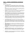
Figures
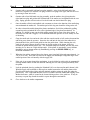
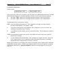
Figure 1 -- Atlantek Model 2400R Plotter . . . . . . . . . . . . . . . . . . . . . . . . . . . . . . . . . . . Page 1
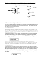
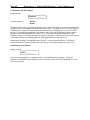
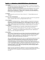
Figure 2 -- Media Threading Path . . . . . . . . . . . . . . . . . . . . . . . . . . . . . . . . . . . . . . . . Page 8
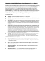
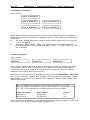
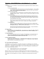
Figure 3 -- Front Control Panel . . . . . . . . . . . . . . . . . . . . . . . . . . . . . . . . . . . . . . . . . Page 11
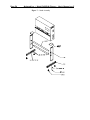
Figure 4 -- Right-Hand Side Panel . . . . . . . . . . . . . . . . . . . . . . . . . . . . . . . . . . . . . . . Page 13
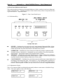
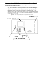
Figure 5 -- Data Interface Configurations . . . . . . . . . . . . . . . . . . . . . . . . . . . . . . . . . . Page 18
Figure 6 -- Interface Handshake Timing . . . . . . . . . . . . . . . . . . . . . . . . . . . . . . . . . . . Page 23
Figure 7 -- Stand Assembly . . . . . . . . . . . . . . . . . . . . . . . . . . . . . . . . . . . . . . . . . . . Page 60
Figure 8 -- Rewinder Assembly . . . . . . . . . . . . . . . . . . . . . . . . . . . . . . . . . . . . . . . . Page 61
Figure 9 -- Rewinder Mechanism . . . . . . . . . . . . . . . . . . . . . . . . . . . . . . . . . . . . . . . Page 63
Figure 10 - Line Voltage Configuration . . . . . . . . . . . . . . . . . . . . . . . . . . . . . . . . . . . Page 71
Figure 11 - Model 2400R Plotter Wiring Diagram . . . . . . . . . . . . . . . . . . . . . . . . . . . . Page 86
Tables
Table 1 -- Interface Connector Pin Assignment . . . . . . . . . . . . . . . . . . . . . . . . . . . . . . .
Table 2 -- Interface Signals and Functions . . . . . . . . . . . . . . . . . . . . . . . . . . . . . . . . . .
Table 3 -- Internal Character Set and Code Assignment . . . . . . . . . . . . . . . . . . . . . . . . .
Table 4 -- Summary for Initialization State . . . . . . . . . . . . . . . . . . . . . . . . . . . . . . . . .
Table 5 -- Summary for Online State . . . . . . . . . . . . . . . . . . . . . . . . . . . . . . . . . . . . .
Table 6 -- Summary for Offline State . . . . . . . . . . . . . . . . . . . . . . . . . . . . . . . . . . . . .
Table 7 -- Summary for Alarm State . . . . . . . . . . . . . . . . . . . . . . . . . . . . . . . . . . . . .
Table 8 -- Summary for Configuration State . . . . . . . . . . . . . . . . . . . . . . . . . . . . . . . .
Table 9 -- Energy Level Characteristics . . . . . . . . . . . . . . . . . . . . . . . . . . . . . . . . . . .
Table 10 - Thermal Media Reference . . . . . . . . . . . . . . . . . . . . . . . . . . . . . . . . . . . . .
Table 11 - Print Voltage Lookup Reference . . . . . . . . . . . . . . . . . . . . . . . . . . . . . . . . .
Table 12 - Troubleshooting Guide . . . . . . . . . . . . . . . . . . . . . . . . . . . . . . . . . . . . . . .
Table 13 - Power-Up Error Codes . . . . . . . . . . . . . . . . . . . . . . . . . . . . . . . . . . . . . . .
Page 19
Page 20
Page 26
Page 28
Page 31
Page 33
Page 36
Page 40
Page 42
Page 58
Page 72
Page 79
Page 84
Atlantek Inc. -- Model 2400R-A Plotter -- User's Manual rev 5
Page 1
1. Introduction
1.1 Scope
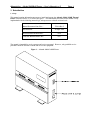
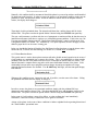
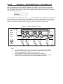
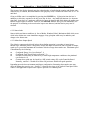
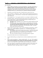
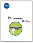
This manual contains information necessary to install and operate the Atlantek Model 2400R Thermal
Plotter (Firmware Series A), as shown in Figure 1. The functionality described in this manual is fully
implemented with the following internal logic microprocessor software revision levels:
Manual Document Num./Rev.:
753014 Rev 5
Date Released:
24 April 1998
Processor Board Software Rev:
A2.6
Controller Board Software Rev:
A2.7
The manual is intended for use by operator and service personnel. However, only qualified service
personnel should be allowed to install and service this equipment.
Figure 1 -- Atlantek Model 2400R Plotter
Page 2
Atlantek Inc. -- Model 2400R-A Plotter -- User's Manual rev 5
1.2 Product Overview
The Model 2400R plotter is a direct-thermal type utilizing continuous roll format thermally-sensitive
media of 24 inch (610 mm) width. The plotter uses a precision thermal printhead with elements spaced
at 1/200 inch (0.127 mm). A variety of different media types are available to meet different user
requirements. The plotter-host interface is compatible with Versatec™ standard for printer/plotters.
1.3 Media
Good quality media is essential for obtaining acceptable imaging performance. Atlantek maintains a
stock of recommended media which will assure top performance, as outlined in Section 9.1. However,
if you do not buy your media from Atlantek, we caution you to specify media with low abrasivity and
moisture content to attain maximum printhead life.
The Model 2400R plotter requires media 24 inches (610 mm) wide, wound coated-side-out on a 1 inch
(25.4 mm) diameter core.
Caution: Use of paper with a high moisture content is to be avoided. This can be determined if during
plot/print, there is noticeable moisture condensed out on the media cut shelf. Such a condition is
deleterious to printhead life. Printheads are not warranted against damage due to operation with media
with a high moisture content.
1.4 Maintenance
The plotter normally should not require any periodic maintenance except for periodic cleaning of the
thermal printhead dot line. Information specific to this task is outlined in Section 4.3. This shall be
necessary when the plotted output exhibits an insufficient blush characteristic in localized positions.
Cleaning of the printhead more often than every 10 rolls of media (approximately 500 feet, or 150 m,
per roll) is a sign that substandard media is in use.
Atlantek Inc. -- Model 2400R-A Plotter -- User's Manual rev 5
Page 3
1.5 Safety
Personnel installing, operating, and maintaining the plotter should be thoroughly proficient in the
installation, operation, maintenance, and service of the plotter. To their safety, and the safety of
operator and maintenance personnel, basic precautions follow. These should be reviewed to promote
safety awareness.
General
!
!
!
!
!
Wear safety shoes, glasses, and gloves when uncrating the equipment.
Wear safety glasses when maintaining or servicing the equipment.
The equipment is heavy. Use sufficient personnel and/or lifting devices for its movement.
Beware of sharp edges, pinch points, and exposed staples when uncrating.
Observe all warnings and cautions, stated or implied, in the procedures.
Mechanical
!
!
!
!
The plotter body can be top heavy when being positioned onto the stand (if used). Never allow
the plotter to sit atop the stand secured by fewer than 2 of the 4 bolts without an assistant
available to hold it in position. Secure all bolts before placing the plotter into service. See
Section 9.2 for specific instructions on installation of plotter onto stand.
Unless specifically instructed otherwise, do not operate the equipment with covers or access
panels removed.
Keep fingers, hands, and tools clear of moving parts.
Route cables properly to eliminate tripping hazards.
Electrical
!
!
!
!
When disconnecting the power cord, tag the prongs of the plug to prevent anyone from
restoring the electrical power.
Do not defeat or bypass built-in equipment safety features.
Replace electrical components with units of equal rating and capacity.
If any panel, cover, or guard must be removed for a given electrical adjustment or check,
extreme caution shall be exercised to prevent personal injury. Wear insulated gloves when
access to energized electrical components becomes necessary.
Page 4
Atlantek Inc. -- Model 2400R-A Plotter -- User's Manual rev 5
2. Specifications
Package Configuration....................... Table Top, paper exits in front of unit also
avail. with optional wall mount or stand
Dimensions .................................... Height: 24.8 inch (63 cm)
Width: 31.5 inch (80 cm)
Depth: 9.4 inch (24 cm)
Weight.......................................... 95 lbs (43 kg), 100 lbs (45 kg) w/ cutter option
Environmental
Operating Temperature.............. 0 to +50/C
Operating Humidity................. 20 to 90% R.H. (non-condensing)
Storage Temperature................-20 to +70/C
Storage Humidity.....................5 to 90% R.H. (non-condensing)
AC Power
Operating Voltage...................User Configurable
100 to 120 VAC, 50/60 Hz or
198 to 242 VAC, 50/60 Hz
Power consumption.................1200 W, 10.0 A max running @ 115 VAC
220 W, max idle load
Data Interface.................................Versatec™-compatible parallel,
2 User Configurable Modes:
Differential mode to 300 ft (91.4 m)
TTL mode to 25 ft (7.6 m)
Output speed
Plot....................................4.0 inch/sec (102 mm/sec), max (588 bytes, Energy Lev 1)
Print...................................1.8 inch/sec (46 mm/sec), max (294 chars, Energy Lev 1)
Resolution (Plot Mode).....................200 dot/in, 588 bytes (4704 pixels), max width
Active plot/print span.......................23.52 inch (597.4 mm)
Image dithering...............................5 possible positions; total dither span ranges over 0.16 inch
(4.1 mm). May be disabled.
Front Panel Controls........................On/Off-Line, Media Feed, Self Test Plot/Print, Media Count
Reset, Config. and Status Polling
Front Panel Indicators.......................LED Lamps: Power, On-Line, Lo Temp, Hi Temp, Alarm
Liquid Crystal Display, 16 character; for Media Count and
Configuration
Recommended media........................Thermal Sensitive Paper or Synthetic 24 in (61.0 cm)
wide, 1 in (2.5 cm) i.d. core Wound coated side out
Accessories....................................Roller Stand
Rewinder
Cutter
Audible Out-of-Paper Alarm
Wall Mount Bracket
Atlantek Part No.
500222
500241
500115
500239
500334
Atlantek Inc. -- Model 2400R-A Plotter -- User's Manual rev 5
Page 5
3. Installation
3.0 General
The general procedure for installing the equipment consists of unpacking, inspecting, moving, installing
and checking. The instructions and safety recommendations set forth in Section 1 constitute a
prerequisite to these instructions.
Note: For basic installation and troubleshooting, it is necessary to locate and
distinguish the two major pc boards in the plotter.
In the Model 2400R, this may be done from the front of the plotter with the front/top
cover panel removed. Both boards are mounted on sliding card guides.
!
The Controller Board is the smaller of the boards and is fully visible.
!
The Processor Board is the larger of the boards, and is hidden in part by the
Controller Board.
3.1 Receiving Inspection
The plotter was carefully inspected and tested prior to shipment. Upon its arrival, inspect the crate or
carton for damage. Unpack the plotter as soon as possible and conduct a thorough examination of the
unit and its components. Do this in the present of the carrier if at all possible. If damage is noted, take
photographs of the damaged portions and immediately file a claim with the carrier. If the carrier is not
notified within 15 days of delivery, it cannot be held responsible.
Information on assembly of the plotter stand and/or rewinder, if ordered, is given in Section 9 -Accessories.
Before placing the plotter into service, note the following items which are secured for shipment:
!
The printhead lift lever, located at the extreme right-hand edge of the media roll compartment,
is secured for shipment with a "tie-wrap" around the casting which supports the right-hand end
of the media roll. This should be cut free for the lift mechanism to function normally.
Consult the following Sections 3.2 through 3.4 for requirements to be considered before operating the
plotter. Section 4 should be followed for basic operator information prior to placing the plotter into
service.
The plotter may be wall mounted with a convenient wall-mount adaptor plate. The four horizontal slots
in the plate may be attached to standard wall studs with centers spaced 16 to 24 inch (41 to 61 cm)
apart. Use lag screws of ¼ inch (6 mm approx) diameter, 1½ inch (38 mm approx) minimum length.
Warning: The plotter with a full roll of media weighs approximately 124 lbs (57 kg). Make sure the
wall mounting plate is adequately fastened to the wall.
Page 6
Atlantek Inc. -- Model 2400R-A Plotter -- User's Manual rev 5
3.2 Line Power Input Requirements
This equipment is provided with moveable voltage selector jumpers at the AC-to-DC power supplies to
allow use with incoming line voltages in the range of 100-120 or 198-242 V AC, single phase, 48 to 62
Hz. If the electrical power supply (as measured during normal operation of the equipment) falls outside
these ranges, a voltage correcting transformer must be used. The line voltage configuration as shipped
is 100-120 V ac, unless the plotter is externally tagged otherwise.
Caution: The electrical installation should conform to the codes and requirements of the country or
locality in which the equipment is to be installed, The power outlet must be installed near the
equipment and be easily accessible. Check for adequate capacity in the line service when choosing the
site for the plotter installation. See Specifications for maximum electrical load characteristics. The line
service should be properly grounded to insure operator safety.
The plotter is supplied with a 6 foot (183 cm) appliance line cord with a plug suitable for use in North
America for 115 V ac operation. Similar cords are available for use in other countries.
For the safety of service personnel, observe sensible practices to insure that line power is not
inadvertently applied to a plotter while the case or rear panel is removed for service or inspection
procedures.
3.3 Line Voltage Selection
There are two power supplies in the Model 2400R, both of which have specific strapping requirements
which must be followed according to the line voltage range. These are is located in the left-hand side
of the plotter chassis, above the thermal printhead. They may easily be observed with the front/top
cover panel removed. Section 10.4 gives specific instructions for configuring both power supplies.
Caution: Be certain that the voltage selector jumpers for both power supplies are set properly before
connecting electrical power.
3.4 Data Interface Configuration
The plotter data input is Versatec™ parallel-format compatible and can be configured for either single
ended (TTL compatible) or differential (long line) data interfaces. Configuration is accomplished by
the position of a jumper plug or switch on the Processor Board, together with the choice of connector
on the Processor which is to receive the interface cable from the external 37-pin data connector to
which the user host system connects. To do this, the plotter front/top cover must be removed (see
Section 10.1). This change is fully described in Section 5.1 and Figure 5.
Unless otherwise specified at the time of order, the plotter is shipped from the factory configured for
the differential data interface. A standard Versatec™ data interface cable may be used to connect the
plotter to the host system. A complete description of the parallel data interface is given in Section 5 -Data Interface.
Atlantek Inc. -- Model 2400R-A Plotter -- User's Manual rev 5
Page 7
4. Basic Operation and Controls
This section describes the user-accessible controls and indicators used on the plotter and describes basic
operating procedures. It is recommended that operator read this section in its entirety before
performing any procedure.
4.1 Printhead Lift Mechanism
In order to facilitate media loading, a printhead lift mechanism is implemented which can be actuated
by the operator. The lift lever can be easily seen at the extreme right-hand edge of the mechanism, in
the opening in the front of the plotter case. Simply pull this lever out and upwards to unlock the
printhead and lift it into an upwards position, useful for media loading or head cleaning should this be
necessary. When it is desired to restore the printhead to its operational position, push the lever
downwards and in until the detent is felt.
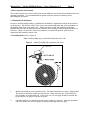
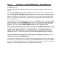
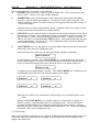
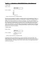
4.2 Loading Media (refer to Figure 2)
Note: Media loading may be performed with power On or Off.
Figure 2 -- Media Threading Path (right-hand side view)
1.
Identify and install the correct thermal media. The right-hand media core plug is spring loaded.
The media roll should be loaded onto this end first. Some units may have a retractable core
plug assembly on the left-hand side. If this is the case, the core plug should be retracted first
by moving the core plug lever up and to the left.
2.
Orient the media roll so that the loose end comes off the top of the roll. Insert the right-hand
end of the media core onto and against the spring-loaded right-hand core plug.
Page 8
Atlantek Inc. -- Model 2400R-A Plotter -- User's Manual rev 5
3a.
On units with a retractable left-hand core plug assembly, swing in the left-hand end of the
media roll, align the core with the core plug, slide the core plug to the right, and lock the lever
by moving it down in its track.
3b.
On units with a fixed left-hand core plug assembly, push the media to the right against the
right-hand core plug and position the left-hand end of the media core in alignment with the core
plug. Spring pressure will assist the roll to the left and onto the left-hand core plug.
4.
Once the media roll has been installed, take a moment to observe the function of the media drag
arm underneath the media roll. The mohair pad of this drag arm should be riding on the roll.
5.
In order to thread the media through the plotter mechanism, first lift the printhead by pulling
out-and-up on the printhead lift lever at the right-hand edge of the plotter mechanism. In
addition, it is helpful to snap out the black media cutting shelf in front of the drive platen. If
the media web free end is ragged, it is recommended that the operator cut it off cleanly for ease
of threading.
6.
Grasp the media web free end at the sides with the coated (outside of roll) surface down and the
end facing away from the operator. Insert the free end into the slot below the rubber drive
platen and above the gold-colored guide bar into the guide chute. While inserting the web,
watch for the end to emerge from the plotter on the top surface of the platen, in the slot
between the platen and the plotter case. It is sometimes helpful to laterally shift the web while
inserting it or to insert at a slight oblique angle. If the plotter is operational, it may facilitate
threading to trigger platen rotation by momentarily pressing the PAPER FEED key, as
described in Section 6.4.2.
7.
When the free end has emerged above the platen, grasp it and pull it through approximately 1 to
2 ft (30 to 60 cm). Draw the web down to the supply roll and attempt to align the edges of the
outfeed portion of the web laterally with the supply roll.
8.
If the web is not square through the mechanism, it can be shifted to achieve this by momentarily
relaxing manual tension on the web and then centering the web with a quick pull laterally near
the platen.
9.
Lock the printhead down by pushing the Printhead Lift Lever down-and-in until a detent is felt.
Wind the supply roll backwards to take up loose media between the roll and the platen roller.
Check that the media rides tightly and with minimal wrinkles against the guide bar under the
platen roller. This is important because excessive wrinkles can cause inadvertent tripping of the
Media-Out Sensor, which is located in the forward-facing surface of the guide bar. It may be
necessary to repeat Step 8 until the media is square through the mechanism.
10.
Close the door to the media compartment.
Atlantek Inc. -- Model 2400R-A Plotter -- User's Manual rev 5
Page 9
4.3 Printhead Cleaning
The printhead does not require frequent cleaning with normal usage. Occasionally deposits may build
up on the printhead which hinders effective heat transfer to the thermal media, and can result in poorly
defined images. This is usually a sign of low-grade media in use.
Should it become necessary to clean the printhead, open the front door and raise the printhead using the
printhead lift lever. The thermal elements are approximately 0.6 inch (15 mm) back from the edge of
the printhead carrier block. Use a cotton cloth gauze or clean rag (make sure there are no metal
fragments on it!) soaked in isopropyl alcohol. Work the cloth in sufficiently to bear upon the thermal
elements and then wipe the printhead laterally while applying upward pressure. Difficult cases may
require persistent cleaning action.
For very stubborn deposits, 3M Wetordry™ Model 3M 281Q polishing paper (US Mesh: 6000) is a
durable material which may used with isopropyl alcohol to enhance cleaning action.
If it is found to be necessary, wrap the cleaning material around the end of the wooden cleaning stick
provided with the plotter or equivalent implement. This may be of assistance in scrubbing of the dot
line. It is not necessary to insert the stick any more than 1 inch (2.5 cm) beyond the cover lower edge in
order to bear upon the dot line.
Note: The recommended cleaning stick is an ordinary tongue-depressor, 1/16 inch (1.6 mm) minimum
thickness, available through most pharmacies or medical equipment suppliers.
Caution: The thermal printhead is a fragile ceramic substrate containing active electronic circuits. Use
extreme care to avoid damage when cleaning or servicing. Never use metal objects to clean the
printhead dot line, as it can be easily damaged by this. Do not insert any implement thinner than 1/16
inch (1.6 mm) between the printhead and platen as this may damage circuitry along the bottom surface
of the printhead. The warranty does not cover printheads damaged by misuse.
After cleaning, allow 1 to 2 minutes for the alcohol to dry before reloading media.
Page 10
Atlantek Inc. -- Model 2400R-A Plotter -- User's Manual rev 5
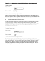
4.4 Front Panel Indicators and Controls
This section describes the function of front panel indicators, display, and keys in the basic Online and
Offline operational states. A detailed discussion of these features as they relate to all operational states
is given in Section 6 -- Operational States.
Figure 3 -- Front Control Panel Layout
4.4.1 Pushbutton Keys
!
ONLINE -- Pushbutton key that toggles the unit's status between Online and Offline. Online
state activates the plotter data interface and disables PAPER FEED and SELF TEST controls.
Offline state disables the plotter data interface and enables these controls.
!
PAPER FEED -- Pushbutton key that, when pressed and held, produces continuous media
feed until released. Alternatively, a momentary key press produces a Form Feed equivalent
media advance. This function operates only when the plotter is Offline
SELF TEST -- Pushbutton key that upon momentary press, triggers output of the configured
Test pattern. This function operates only when the plotter is Offline. It allows easy user check
on plotter functions without requiring connection to a host system.
!
!
COUNTER RESET -- Pushbutton key switch that resets the media usage counter displayed on
the display to the selected reset value. This could be "0" if Up counting mode is selected, or a
preset number (this would normally be set to media roll size in feet) if Down counting mode is
selected. When the plotter is Offline, this key is also used to access the Configuration menues.
4.4.2 Alphanumeric Display
This is a 16-character liquid crystal display that normally indicates current status of the Media Usage
Count. This report appears as one of the following:
64444444444444444447
644444444444444 44447
5Media Used: ___ft
5
5Media Left: ___ft
5
94444444444444444448
944 4444444444444 4448
64444444444444444447
5MediaUsed: ___ m
5
94444444444444444448
64444444444444444447
5MediaLeft: ___ m
5
94444444444444 444448
Atlantek Inc. -- Model 2400R-A Plotter -- User's Manual rev 5
Page 11
depending on whether the Media Count is configured for the Up or Down-counting modes, respectively
(see Section 7.10). The number displayed represents the amount of media used or remaining (assuming
correct configuration of the Media Reset Length and proper actuation of the COUNT RESET key).
The unit of the length display can be either in feet (ft) or meters (m) according to the configured
Display Unit (see Section 7.11). The number displayed represents the amount of media used or
remaining (assuming correct configuration of the Media Reset Length and proper actuation of the
COUNT RESET key). The length count is updated based upon anticipated chart motion as performed
by the chart drive stepper motor. As such it may be misleading if the user manually pulls through or
backs up a significant length of chart. The length count as displayed is continually updated into nonvolatile memory and so its value is preserved through a power-down period.
4.4.3 Indicator Lamps
!
POWER -- Green lamp lit indicates presence of +5V logic power.
!
ONLINE -- Green lamp lit indicates that the plotter is in Online state, suitable for host interface
driven operation.
!
LOW TEMP -- Yellow lamp lights whenever the printhead operating temperature is below the
normal range (approximately 40/C), as determined by the thermostatic printhead background
temperature controls. This will normally occur only in the first few minutes after power up of
the plotter.
!
HIGH TEMP -- Yellow lamp lights whenever the printhead operating temperature approaches
the upper limit of the normal safe operating range (approximately 60/C), as determined by the
thermostatic printhead background temperature controls. This will normally occur only under
conditions of exceptionally heavy and fast plotting. From approximately 52/C and above, this
lamp shall flash, thus indicating that the print/plot speed is being limited on account of
temperature. As the printhead temperature rises further, the flash rate shall increase, and
output speed limited further. This technique is employed to limit printhead temperature rise
such that no interruption of plotting shall be encountered. However, if temperature nonetheless
rises to the upper limit, the print/plot output shall be blanked, and the lamp shall indicate this
by being On constantly for the duration of this condition.
ALARM -- Yellow lamp lights when any condition is sensed that prevents normal operation
and could require corrective action by the operator. Usually this would result from a
mechanical fault detected through one of the sensors. The alarm is explained on the display.
!
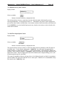
4.5 Side Panel Functions (refer to Figure 4)
!
Power On/Off Switch -- Two position rocker switch that applies AC power to the power
supplies. The position marked with a "0" indicates the Off state. The position marked with a
"|" indicates the On state.
!
Fuse -- Fuse in series with the AC input wiring to both power supplies. In the event that
replacement is needed, use a 10 A slow-blow fuse for 115 V AC operation or a 5 A slow-blow
fuse for 230 V AC operation.
!
Line Power Connector -- IEC-type line input connector. Attach the proper line cord for
intended installation.
!
Data Input Connector -- A 37-pin D connector used for the parallel data interface. A
standard Versatec™ cable may be used here. Table 1 details the pin assignments.
Page 12
Atlantek Inc. -- Model 2400R-A Plotter -- User's Manual rev 5
Figure 4 -- Right-Hand Side Panel Layout
4.6 Protective Sensors and Operator Interaction
The plotter is equipped with optical sensors that serve to protect the internal components and to provide
useful prompts to the user when the plotter is not in an operable condition. The function of these may
have impact on everyday usage of the plotter.
4.6.1 Printhead Lift Sensor
As outlined above, the plotter is equipped with a printhead lift mechanism, activated manually by the
lever at the right side of the mechanism. The printhead must be engaged in the print position whenever
the printhead is activated. This prevents damage to the printhead from improper heat sinking of the dot
elements when energized in free air.
To insure that the printhead is properly engaged, a flag mounted to the pivot arm of the printhead lift
lever interrupts the light beam of a gap-interrupt type optical sensor mounted to the right printhead
support strut. As soon as the printhead moves out of the fully engaged position, the flag moves out of
the sensor gap, and print/plot and media advance are disabled. The ALARM lamp shall light, and the
front panel display shall indicate:
64444444444444444447
5 Printhead Lifted
5
94444444444444444448
In order to restore the plotter to an operational condition, simply push the printhead lift lever
downwards and in until the detent is felt. The alarm should then clear, and the plotter shall be in the
Offline State. The plotter can then be placed Online if desired using the ONLINE front panel key.
4.6.2 Media-Out Sensor
A media-out sensor is provided to protect the printhead and mechanism from unnecessary wear and to
alert the operator in the event that media is consumed. This sensor is an infrared reflective LED device
and is mounted behind the front surface of the extruded media guide chute, as illustrated in Figure 2.
The sensor is directed outward such that it detects the presence of media as it wraps around the front
part of the extruded chute. When this reflective surface is lost, as happens when media is consumed,
print/plot and media advance are disabled. The ALARM lamp shall light, and the front panel display
shall indicate:
64444444444444444447
5 Out of Media
5
Atlantek Inc. -- Model 2400R-A Plotter -- User's Manual rev 5
Page 13
94444444444444444448
Naturally, this condition shall be encountered should the plotter be powered up with no media installed.
No harm can result from this. In order to restore the plotter to an operational condition, make sure the
printhead is lifted, and install the media. When the media-out sensor detects an adequate reflective
surface, the display shall change to:
64444444444444444447
5 Printhead Lifted
5
94444444444444444448
Then simply lock the printhead down. The alarm should then clear, and the plotter shall be in the
Offline State. The plotter can then be placed Online if desired using the ONLINE front panel key.
The user could encounter a problem with the use of transparent or translucent films in that there may be
insufficient reflectance from these to register as a valid media-present condition. If this is the case, the
User may mask Media Sensing using the "Media Sense Enable/Disable" control available in the User
Configuration Menu (see Section 7.4). Alternatively, as a quick expedient, the user can apply a white
adhesive paper label over the sensor viewing port.
In the case that Media Sensing is Disabled, the Stall Sense in effect functions to stop the plotter when
media runs out, in which case Stall Sensing (see Section 10.1) should never be disabled.
4.6.3 Platen Rotation Sensor
This optical sensor is used to detect platen rotation stall and to disable normal operation in the event of
a belt breakage or a mechanical jam, or motor drive failure. This is accomplished by a chain sprocket
mounted to the left side of the platen roller that serves to interrupt the sensor beam as it rotates. The
internal electronics compares motor step pulses with sensor-determined rotation of the platen. If the
relationship between motor steps and platen rotation changes beyond an acceptable error range,
print/plot and media advance are disabled. The ALARM lamp shall light, and the front panel display
shall indicate:
64444444444444444447
5 Mechanism Stall
5
94444444444444444448
Whenever this condition occurs, inspect the unit and, if possible, cure the cause of the alarm. Lifting
the printhead shall then cause the display to change to:
64444444444444444447
5 Printhead Lifted
5
94444444444444444448
In order to restore the plotter to an operational condition, simply push the printhead lift lever
downwards and in until the detent is felt. The alarm should then clear, and the plotter shall be in the
Offline State. The plotter can then be placed Online if desired using the ONLINE front panel key.
In the event of a belt breakage, motor drive failure, or other problem that is not immediately
remediable, contact the factory or authorized service agent for assistance.
Actions of the plotter in the event of these conditions is further explained in the upcoming discussion of
the "Fault Handler" operational state.
Page 14
Atlantek Inc. -- Model 2400R-A Plotter -- User's Manual rev 5
4.7 Initial Power-Up
After the proper media has been loaded, apply AC power by setting the power switch to the On (|)
position.
The Front panel POWER indicator should illuminate to indicate that power has been applied. At this
time, the LOW TEMP, HIGH TEMP, and ALARM indicators should come on as the unit initializes.
The initialization process takes approximately 15 seconds and allows the machine to perform a internal
diagnostics, including a test of the sensors. Various messages are reported on the display during this
period. The sensor test is indicated by the stepper motor jogging the media forward slightly to check
the media transport sensor.
Once initialized, the unit will normally enter the Online state (ONLINE indicator on) and the ALARM
indicator should go off. The LOW TEMP indicator will stay on if the plotter has been idle for some
time. Take the unit to Offline state (ONLINE indicator off) by pressing and releasing the ONLINE
pushbutton. Press the front panel PAPER FEED pushbutton to verify normal media feed.
After the media feed function has been verified, press and release the SELF TEST pushbutton. Check
the self-test printout to be sure the self-test pattern prints properly. The self-test pattern will be one the
available patterns outlined in Section 7.2 -- Test Pattern Selection. The default test pattern is the
"Zigzag", and this pattern should appear upon actuation of Self Test until the plotter is configured
differently by the user. This pattern verifies proper internal data manipulation and print consistency.
Connect the data interface to the plotter via the data connector on the right side of the unit. Press and
release the front panel ONLINE pushbutton to put the unit back to Online state. Online state is
confirmed by the illuminated ONLINE indicator.
Use a Versatec™ compatible data source to drive the plotter and verify normal operation. If the plotter
has been Off for long at normal room temperatures, the LOW TEMP indicator will remain illuminated
for 10 to 15 minutes after initial power-up. This indicates that the printhead is not fully up to operating
temperature. Plots run during this time may be slightly lighter than normal.
Atlantek Inc. -- Model 2400R-A Plotter -- User's Manual rev 5
Page 15
5. Data Interface
The following information is intended for system integrator, programmers, installers, and service
personnel to assist in configuring the host system used with the plotter.
5.0 General
The plotter is a 200 dot/inch (8 dot/mm, approx.) unit capable of plotting up to 4.0 inches per second
(102 mm per second) in a plot (raster data) mode. The plotter can operate as either a plotter or, using
the internal character generator, as a printer. In the plot mode it has a width capacity of 588 bytes
(4704 pixels).
The interface to the plotter is designed to be compatible with the Versatec™ parallel interface, as
defined in Electrostatic Printer/Plotter Interface Specification, Bulletin Number 312, September, 1977.
Clarifications and/or modification to this specification are contained in V80 Series Electrostatic
Printer/Plotter Specification. Bulletin Number 476, December, 1979.
The plotter data interface supports both the plot-only and print-only Versatec™ compatible data interface
modes. The simultaneous print/plot mode, as defined by the Versatec™ interface specifications, is not
currently supported by the plotter.
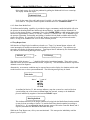
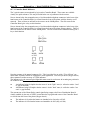
5.1 Parallel Interface Signals
The plotter connects to a host system via a 37-pin D connector. The connecter mounted on the plotter
has pin contacts (DB-37P). The electrical interface is factory set for differential (long lines)
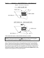
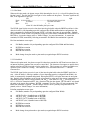
configuration, but may be configured for TTL (single ended). Selection is done by connecting the
internal ribbon cable from the D connector to the appropriate connector on the Processor Board and by
application of the three pin jumper plug in the appropriate position as illustrated in Figure 5. Some
versions of the Processor Board may be equipped with a slide switch in the location of the jumper with
the positions labelled "DIF" and "TTL". To examine and/or change this, the plotter front/top cover
must first be removed (see Section 10.2).
Page 16
Atlantek Inc. -- Model 2400R-A Plotter -- User's Manual rev 5
Figure 5 -- Data Interface Configurations
NOTE: SOME UNITS HAVE A SLIDE SWITCH INSTEAD OF A SHUNT
Important: To insure proper interface function, both the ribbon cable between the panel-mounted
interface connector and the Processor Board and the jumper plug (or slide switch if so equipped) on the
Processor Board must be set properly according to the desired interface format.
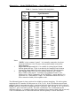
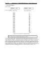
Table 1 lists the pins of interface connector with the signal names for both the TTL and differential
interfaces. Table 2 lists the signals and gives a functional description of each. The plotter interface
consists of eight data lines, one print/plot mode select line, six command lines, and two status output
lines. In the case of the TTL-compatible format, each signal is communicated by one physical line, all
being referenced to digital ground. In the case of differential format, each signal is communicated by
an active high/low line pair. The digital ground connection over the interface cable in this case is not
required, but is provided at the connector. Usually this connection (shown as DGND in Table 1) will be
in parallel with the equipment safety earth-ground connections.
Atlantek Inc. -- Model 2400R-A Plotter -- User's Manual rev 5
Page 17
Table 1 -- Interface Connector Pin Assignment
D
Conn'tr
Pin
Number
1
2
3
4
5
6
7
8
9
20
21
22
23
24
25
26
27
28
10
29
11
30
12
31
13
32
14
33
15
34
16
35
17
36
18
37
19
Notes:
1.
2.
Signal Mnemonic
TTL
IN1
IN2
IN3
IN4
IN5
IN6
IN7
IN8
CLEAR.L
PICLK.H
READY.L
PRINT.H
DGND
DGND
DGND
DGND
DGND
DGND
DGND
DGND
DGND
DGND
DGND
DGND
reserved
** Note2 ** INOP.H
reserved
DGND
RESET.L
DGND
RFFED.L
DGND
REOTR.L
DGND
RLTER.L
DGND
INOP.H ** Note 2 **
Differential
IN1+
IN2+
IN3+
IN4+
IN5+
IN6+
IN7+
IN8+
CLEARPICLK+
READYPRINT+
IN1IN2IN3IN4IN5IN6IN7IN8CLEAR+
PICLKREADY+
PRINTDGND ** Note 1 **
INOPreserved
reserved
RESETRESET+
RFFEDRFFED+
REOTRRESET+
RLTERREOTR+
INOP+
"DGND" is logic common "ground". It is internally connected to the plotter
frame and from there to the AC power earth ground terminal on the power
input connection.
(Differential interface only) Pin 13 is available for joining Digital Ground
between plotter and host. If this is not desired, the connection can be broken
by removing Jumper Shunt JP4 on the plotter Processor PC Board Assembly.
(TTL interface only) These pins carry identical INOP.H (Low=Online,
High=Offline) status outputs. According to the published Versatec™ TTL
interface specs, Pin 32 is expected to be an "ONLINE.L" output, and Pin 19 is
expected to be a "NOPAPER.H" output. For installations which follow this, a
direct connection should yield acceptable results.
The differential format is always preferred for reliable host-plotter interfacing. We advise against
employing the TTL interface for cable runs over 25 ft (7.6 m). If the TTL interface must be used,
make sure that the interconnecting cable is constructed with each signal wire paired with its adjacent
DGND contact in a twisted pair configuration (pin 1 with pin 20, pin 2 with pin 21, etc., up to pin 18
with pin 37; pin 19 need not be paired). This cable construction is also recommended for the
differential interface. A continuous cable shield, terminated to the connector metal shells at each end,
is also recommended both to reduce EMI emissions and susceptibility to outside interference.
Page 18
Atlantek Inc. -- Model 2400R-A Plotter -- User's Manual rev 5
Table 2 -- Interface Signals and Functions
Signal
Function
TTL Active
Level
IN1
Parallel Input Data (LS Bit)
IN2
Parallel Input Data
IN3
Parallel Input Data
IN4
Parallel Input Data
IN5
Parallel Input Data
IN6
Parallel Input Data
IN7
Parallel Input Data
IN8
Parallel Input Data (MS Bit)
PICLK
Parallel Input Clock (False-to-True)
High=True
PRINT
True=Print; False=Plot
High=True
RLTER
Line terminate command
RFFED
Line term w/ Form Feed command
REOTR
Line term w/ EOT command
CLEAR
Line term w/ Buffer Clear
RESET
Interface Reset
READY
True= Ready to receive byte
Low= True
INOP
True= Offline; False= Online
High=True
Plot
Polarity
True=
Black
False=
White
Source
High=
True
Low=
False
Host
Low= True
Plotter
The interface signal functions are as follows:
!
IN1 through IN8 contain the data to be printed or plotted. These lines are monitored by the
plotter with every PICLK. The data line should be changed only when PICLK is false.
!
PICLK, when true, indicated that a byte of data is ready for transmission to the plotter. This
line should go true only when READY is true and INOP is false; otherwise, it will be ignored.
When the PICLK signal has been accepted by the plotter, READY will go false to signal the
host to remove PICLK and the data.
!
PRINT when true, indicates that the print mode of operation is selected; when false, it
indicated that plot mode is selected. This signal is monitored by the plotter with every
command signal. PRINT should be changed only when PICLK and the remote commands are
false.
!
RLTER, when true, indicates that any data in the print or plot buffer is complete and is to be
printed/plotted, with accompanying normal chart advance (ie. no extra feed) for that plot or
print line. This line should go true only when READY is true and INOP is false; otherwise, it
will be ignored. When the RLTER has been accepted by the plotter, READY will go false (ie.
busy) indicating the host should remove RLTER.
Atlantek Inc. -- Model 2400R-A Plotter -- User's Manual rev 5
Page 19
!
RFFED, when true, indicates that any data in the print or plot buffer is complete and is to be
printed/plotted, after which the media is to be advanced in accordance with the Form Feed
function, as configured. Response to Form Feed is outlined in Section 7.13 -- Form Feed
Length. Default action is to feed 2.5 inch (63.5 mm) of chart. This line should go true only
when READY is true and INOP is false; otherwise, it will be ignored. When the RFFED has
been accepted by the plotter, READY will go false (ie. Busy) indicating the host should remove
RFFED.
!
REOTR, when true, indicates that any data in the print or plot buffer is complete and is to be
printed/plotted, after which the media is to be advanced in accordance with the End of
Transmission Advance function, as configured. Response to this is outlined in Section 7.14 -End of Transmission Advance Length. Default action is to feed 8.0 inch (203 mm) of chart.
This line should go true only when READY is true and INOP is false; otherwise, it will be
ignored. When the REOTR has been accepted by the plotter, READY will go false (ie. busy)
indicating the host should remove REOTR.
!
CLEAR, when true, indicates that any data in the print or plot buffer is to be cleared. Any
partial data lines which have been received but yet to be plotted/printed are lost. This line
should go true only when READY is true and INOP is false; otherwise, it will be ignored.
When the CLEAR has been accepted by the plotter, READY will go false (ie. busy) indicating
the host should remove CLEAR.
!
RESET, when true for 100 nsec or more, forces the plotter to reset the interface hardware.
Any partial data lines which have been received but yet to be plotted/printed are lost. Function
is similar to CLEAR except that it is not dependent upon the READY signal being asserted in
order to be effective. This line is honored by the plotter when in Online state only.
!
READY, when true, indicates that the plotter is ready to accept a new data byte or command
from the host system. READY is set false, to indicate that the plotter is busy, approximately
120 nsec after the receipt of a asserted signal from any one of PICLK, RLTER, RFFED, or
REOTR from the host system. As soon as READY goes false, the host system should remove
the data or command. READY will be brought true after the data or command has been
processed and the command from the host has been removed, thus confirming that a new data
byte or command may be received. READY is also set false at start-up and stays false until all
of the internal power-on reset processing is completed and the plotter is in Online state.
!
INOP, when true, indicates that the plotter is inoperable through the host interface for some
reason. This could mean that either the plotter is in Offline state or an Alarm condition exists.
If an Alarm exits, the display panel on the plotter should report a message indicating the cause.
INOP will be brought false after the ONLINE key has been toggled to put the plotter to Online
state (assuming any problem conditions have been fixed). INOP is also set true at start-up and
stays true until all of the internal power-on reset processing is completed.
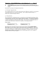
5.2 Handshake Protocol
The plotter interface uses a simple software handshake protocol. Whenever READY is true, the host
system is allowed to assert a command signal (one of PICLK, RLTER, RFFED, CLEAR, or REOTR).
After a settling delay of approximately 120 nsec, the command is accepted and READY is negated.
When the host system has detected READY going false, it responds by negating the command. After
the internal processing is complete, the interface logic re-examines the command signals and asserts
READY, if and when they are all negated. If the host system either fails to negate the command or
negates it and re-asserts another command before the READY has been re-asserted, the interface will
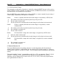
stay busy forever. The timing diagram in Figure 6 illustrates the interaction of the various command
and status lines.
Only one command signal should be activated at a time, otherwise the interface may arbitrarily process
one and ignore the other. RESET will override any other command signal and will be accepted
whenever the plotter is in Online state.
Page 20
Atlantek Inc. -- Model 2400R-A Plotter -- User's Manual rev 5
Remote command lines RLTER, RFFED, REOTR, and CLEAR are polled upon the completion of
their assigned functions. If the command signal has not been negated as of this time (10 :sec, min,
after the negation of READY in response to the command), then an internal trap shall be actuated and
an alarm message of the form:
64444444444444444 447
5 Halt:Intfc _____
5
9444444444444444 4448
shall be displayed on the front panel. The "_____" field shall indicate the command line effected. The
plotter must be power cycled to resume normal function. The most probable cause of this is a faulty
host interface system or interconnecting cable. Possibly, this may result from failure of the host driver
hardware to initialize promptly with all command signals to the plotter in a negated state.
Figure 6 -- Interface Handshake Timing
Notes:
1.
IN1-8 and PRINT should be stable by the time of the asserting edge of PICLK.
2.
Delay from asserting edge of (any of) PICLK, RLTER, RFFED, REOTR, and
CLEAR to negating edge of READY, 120 ns nominal.
3.
IN1-8 and PRINT should be stable until negating edge of READY.
4.
READY shall be reasserted following line terminating condition when interface
is able to receive next data line or remote line termination command.
Atlantek Inc. -- Model 2400R-A Plotter -- User's Manual rev 5
Page 21
5.2.1 Plot Mode
When used in plot mode, the plotter accepts 8-bit data and plots it as is (ie. a dot will be plotted for any
bit that is true). The plot line fills from right to left as media exits the plotter. The most significant bit,
IN8, is the rightmost bit per byte.
left
right
Pixel: 99999999-------------------------------9999999999999999
Bit:
01234567
0123456701234567
Byte:
N-1
1
0
where N is the full buffer plot byte count
The PICLK signal clocks successive data bytes into the plot buffer when the PRINT mode line is false.
After the buffer is full (depending upon the configured Plot Width and Resolution configuration), the
data is automatically plotted and subsequent PICLK's will place data onto the next plot line. Partially
full plot buffers can be forced to be plotted by using one of the remote commands (RLTER, RFFED, or
REOTR) or via a mode change (refer to "Mode Changes" for more information). A remote line
terminate, RLTER, immediately following an automatic Full Buffer line termination is ignored.
Plot line termination occurs upon:
!
Full Buffer (number of bytes depending upon the configured Plot Width and Resolution)
!
!
!
RLTER line assertion
RFFED line assertion
REOTR line assertion
!
Mode change from plot mode to print mode (recognized upon PICLK assertion)
5.2.2 Print Mode
When used in print mode, the plotter accepts 8-bit data bytes encoded in ASCII and converts them via
an internal character generator into successive raster lines. The characters first appear as upside-down,
and the print line will fill from right to left as media exits. This is proper as it results in readable text,
when the chart is turned for viewing. This character set is described in Section 5.3 -- Internal
Character Set.
The PICLK signal clocks successive bytes of data into the print buffer when the PRINT mode line is
true. After the buffer is filled up (number of bytes depending upon the configured Print Width), the
buffer is automatically formatted and printed. Subsequent PICLK's will place data onto the next print
line. Partially full print buffers can be forced to be printed by using one of the remote commands or by
embedding either the ASCII Carriage Return (CR, 0Dhex), Line Feed (LF, OAhex), Form Feed (FF,
OChex), or End of Transmission(EOT, 04hex) characters into the data stream. The CR and LF are treated
the same as the remote line terminate, RLTER, command. The first CR or LF after an automatic Full
Buffer line terminate is ignored. A mode change will also cause a partially full print buffer to be
printed (refer to "Mode Changes" for more information).
Print line termination occurs upon:
!
Full Buffer (number of bytes depending upon the configured Print Width)
!
!
!
!
ASCII CR (0Dhex) (handled same as RLTER)
ASCII LF (OAhex) (handled same as RLTER)
ASCII FF (OChex) (handled same as RFFED)
ASCII EOT (04hex) (handled same as REOTR)
!
!
!
RLTER line assertion
RFFED line assertion
REOTR line assertion
!
Mode change from print mode to plot mode (recognized upon PICLK assertion)
Page 22
Atlantek Inc. -- Model 2400R-A Plotter -- User's Manual rev 5
5.2.3 Plot/Print Mode Changes
The current plot or print mode of the plotter is selected by setting the PRINT line true or false, prior to
issuing a PICLK or remote command. In normal operation, the PRINT line would be set to the desired
state and left there for the duration of the operation.
Since the PRINT line can be changed prior to either a PICLK or a remote command, the processing of
a mode change is dependent on the sequence of commands.
Case 1:
A.
B.
C.
Case 2:
A.
B.
C.
Case 3:
A.
B.
Case 4:
A.
B.
If there is a partially full buffer and a mode change is recognized by a PICLK, then:
The contents of the buffer are printed or plotted as per the prior state;
The new mode is entered; and
The date byte that was coincident with the mode change is the first data for the new mode.
If there is a partially full buffer and a mode change is recognized by a remote
command, then:
The contents of the buffer are printed or plotted as per the prior state;
The command is executed; and
The new mode is entered.
If the data buffer is empty and a mode change is recognized by a PICLK, then:
If the new mode is entered; and
The data byte that was coincident with the mode change is the first data for the new mode.
If the data buffer is empty and a mode change is recognized by a remote command,
then:
The command is executed; and
The new mode is entered.
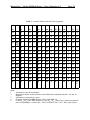
5.3 Internal Character Set
The internal ROM-based font for printing characters is stored and printed at full 200 dot/inch (8
dot/mm, approx) resolution. In the defined font, the character cell is (width x height) 16 x 20 dots or
0.080 inch (2.03 mm) by 0.100 inch (2.54 mm). This cell includes both the intercharacter and interline
spacing.
The normal printable characters corresponding to codes 20hex to 7Fhex are supported. These are shown
in Table 3. Codes 80hex to FFhex generate the same responses as the analogous code with 80hex
subtracted; with the exception of the control codes (CR, LF, FF, EOT), which only respond with the
most significant data bit (IN8) =0.
Atlantek Inc. -- Model 2400R-A Plotter -- User's Manual rev 5
Page 23
Table 3 -- Internal Character Set and Code Assignment
00
10
20
30
0
40
@
50
P
60
`
70
p
01
11
21
!
31
1
41
A
51
Q
61
a
71
q
02
12
22
"
32
2
42
B
52
R
62
b
72
r
03
13
23
#
33
3
43
C
53
S
63
c
73
s
14
24
$
34
4
44
D
54
T
64
d
74
t
05
15
25
%
35
5
45
E
55
U
65
e
75
u
06
16
26
&
36
6
46
F
56
V
66
f
76
v
07
17
27
'
37
7
47
G
57
W
67
g
77
w
08
18
28
(
38
8
48
H
58
X
68
h
78
x
09
19
29
)
39
9
49
I
59
Y
69
i
79
y
1A
2A
*
3A
:
4A
J
5A
Z
6A
j
7A
z
1B
2B
+
3B
;
4B
K
5B
[
6B
k
7B
{
04
0A
EO
T
LF
0B
0C
FF
1C
2C
,
3C
<
4C
L
5C
\
6C
l
7C
|
0D
CR
1D
2D
-
3D
=
4D
M
5D
]
6D
m
7D
}
0E
1E
2E
.
3E
>
4E
N
5E
^
6E
n
7E
~
0F
1F
2F
/
3F
?
4F
O
5F
_
6F
o
7F
DE
L
Notes:
1.
All character codes in hexadecimal.
2.
Shaded boxes denote control characters with defined line termination functions. See text for
functions.
3.
All blank box codes print as a space.
4.
Character designated as DEL indicates a 50% shade-filled cell.
5.
Codes 80hex-FFhex cause same response as Codes 00hex-7Fhex, respectively, with the exception of
those corresponding to control codes. These (Codes 84hex, 8Ahex, 8Chex, 8Dhex) print a space.
Page 24
Atlantek Inc. -- Model 2400R-A Plotter -- User's Manual rev 5
6. Operational States
6.0 General
This section describes the range of operational states that the Model 2400R may assume. These are as
follows:
!
Initialization -- entered upon power up
!
Online -- normal host driven state
!
Offline -- for media feed and test plotting
!
Alarm -- sensor-based fault condition detected
!
Configuration - operator customization of plotter parameters
!
Trap Report -- internal logical error detected
In the section that follows, each of these operational states is explained in terms of function and user
interactions with the keypad and display.
6.1 Initialization (Power-Up) State
6.1.0 General
In the period immediately following power up, plotter internal electronics performs essential
initialization functions, minimal self test, determines the disposition of the previous plotter
configuration as stored in nonvolatile RAM (NVRAM), and then determines the appropriate operational
state. Several informational messages are output on the front panel display during this period.
One of the first functions of the plotter upon power up is to read the front panel keys. Pressing and
holding a key just prior to switching power on can influence actions in the Initialization state. In all
cases, the key may be released when the first intelligible message has been posted on the display.
Table 4 -- Summary for Initialization State
Indicators
Status
Notes
ONLINE
Off
Interface is inactive (INOP asserted).
ALARM
On
LOW TEMP
On
HIGH TEMP
On
Display
Various messages, refer to text.
Keys
Function
ONLINE
Press at power-up, forces Offline state after Initialization.
PAPER FEED
No function
SELF TEST
Press at power-up, forces Configuration state after Initialization.
COUNTER RESET
Press at power-up, forces Flush of all configuration parameters.
Indicators On for verification purposes only, not indicative of
actual temperature.
Atlantek Inc. -- Model 2400R-A Plotter -- User's Manual rev 5
Page 25
6.1.1 Initialization Keypad Functions
Normal action following Initialization is for the plotter to go to the "WAIT FOR TEMPERATURE"
initial state, assuming internal electronics and sensors indicate all is in order. The "WAIT FOR
TEMPERATURE" message indicates that the plotter is in the process of heating the printhead up to
normal operating temperature of approx. 40o C. We ask that you allow the plotter to reach its normal
operating temperature for the best quality image to be printed,the unit will still plot a file if you put the
plotter on line. Self test and access to the "User and Serv menu's" are restricted until the plotter reachs
its operating temperature, depending upon ambient temperature it will take approx. 10 minutes to do
this.
It may be preferable in a particular environment for the plotter to power-up into the Offline State. This
may be useful if the host is in a unknown state for some time following system initialization and it is
undesirable for the plotter to respond to possible invalid conditions on the interface. One consequence
of this might be for the plotter to feed media continually due to uninitialized outputs from the host. A
good way to prevent this is to configure the plotter such that it doesn't go Online, and therefore is
doesn't respond to the host. The plotter may be placed Online manually by pressing the ONLINE key
when the host has been initialized.
If it is desired to stay Offline upon power-up, the user can reconfigure the plotter "Default Power-Up
State" (see Section 7.15) for "Offline"; this shall take effect upon the following power-up.
Alternatively, the user may press and hold the ONLINE key at power up. This results in the plotter
going to the state following Initialization contrary to that configured in the Default Power-Up State
menu.
Normal action during Initialization is for the plotter to restore the configuration previously in effect.
This will not happen if either of two conditions are detected:
!
!
The COUNT RESET key is seen as pressed at power up.
or
DIP Switch (S2) Station 8 on the Processor Board is On.
Response in either case is for all configurable parameters to be set to known values, a process referred
to herein as a "Configuration Flush". This may be useful for a user to return the plotter to a known
state in case of persistent trouble. This should be done with caution, however, as all parameters may be
affected.
Page 26
Atlantek Inc. -- Model 2400R-A Plotter -- User's Manual rev 5
6.1.2 Display Functions
During Initialization several reports are issued. These are, in sequence:
1.Product model number and software release series
For example:
64444444444444444447
5 Model 2400 -A
5
94444444444444444448
2.Processor Board microprocessor software revision number and checksum:
For example:
64444444444444444447
5 PrRv A2.6e E297
5
94444444444444444448
Note: The Processor Board is one of the 2 major pc boards in the plotter (the
Controller Board is the other). Software revision and checksum of both boards can be
polled in the Configuration State, Service Menu (see Section 8.2).
3.Disposition of internal configuration
One of:
64444444444444444447
5 Confgn Restored
5 (self explanatory)
94444444444444444448
64444444444444444447
5 DefCnfg-UserReq
5 (user requested
94444444444444444448 Configuration Flush)
4.Internal diagnostic result
For example:
64444444444444444447
5 Error Code: Pass
5
94444444444444444448
If any problem was found in these tests, a 4 hex digit error code number would be
displayed in place of "Pass", and this should be reported to Atlantek or its authorized
service agent.
At this point, media advance of approximately 0.3 inch (8 mm) should occur while the internal
physical sensors (Media Present, Printhead Position, Mechanical Stall) are polled to determine
if the plotter is properly configured for operation. If any sensor fault is detected, the Alarm
state s entered for display of the problem and prompting of user for correction. If no fault is
seen, either Online or Offline state is entered, in accordance with the selected Default PowerUp State and user action at power-up as described earlier.
Atlantek Inc. -- Model 2400R-A Plotter -- User's Manual rev 5
Page 27
6.2 Online State
6.2.0 General
In the Online state, and only in this state, the plotter is sensitive to host input over the parallel port.
Specific functions of the parallel port are discussed in Section 5 -- Data Interface. Obviously this state
is intended for the vast majority of functional usage of the plotter.
Table 5 -- Summary for Online State
Indicators
Status
Notes
ONLINE
On
Interface is active (INOP negated)
ALARM
Off
LOW TEMP
Off/On
HIGH TEMP
Off/On
Display
Current Media Used or Media Left status
Keys
Function
ONLINE
Press to go Offline.
PAPER FEED
No function
SELF TEST
No function
COUNTER RESET
Long press to reset Media Count
Both Off or one On in accordance with current printhead
temperature
6.2.1 Online State Keypad/Display Functions
When in the Online state, the only keypad functions supported are reset of the media count (using
COUNT RESET key) and going to Offline state (using ONLINE key).
The function of resetting the Media Count is begun by the user pressing the COUNT RESET key. The
front panel display responds by displaying:
64444444444444444447
5 Hold to ResetCnt
5
94444444444444444448
for approximately 2 seconds. If the COUNT RESET key is released before the end of this period, then
the display shall be restored to its former length message without changing the Media Count. If the key
is held pressed for this period, then at the end of it the display shall change one of the following:
64444444444444444447
64444444444444444447
5 MediaUsed: ___ft
5
5 MediaLeft: ___ft
5
94444444444444444448
94444444444444444448
64444444444444444447
64444444444444444447
5 MediaUsed: ___m
5
5 MediaLeft: ___m
5
94444444444444444448
94444444444444444448
Page 28
Atlantek Inc. -- Model 2400R-A Plotter -- User's Manual rev 5
The format of the display depends upon the selected modes of media length counting and display units.
When the key is released, the actual numeric field (properly reset) is inserted in front of the "ft" or "m"
unit label.
Going to Offline state is accomplished by pressing the ONLINE key. If plot/print from the host is
underway at this time, response to the key press may be slow. Any multi-line functions (ie. character
print lines, form feed, etc.) underway when the key press is detected shall finish before the media stops
and the keypad request is honored. However, the ONLINE indicator does goes Off immediately for
the purpose of confirming to the user that the request was detected, and that the key may now be
released.
6.2.2 Sensor faults
Sensor-fault based alarm conditions (ie. Out of Media, Printhead Lifted, Mechanism Stall) which occur
while in the Online state cause immediate stoppage of any plot/print which may be underway and
change to the Alarm state.
6.2.3 Online State Output Speed
The effective output speed achieved in host-driven Online operation is a product of many factors.
Internal logic within the plotter is designed to accept data input from the host and to regulate its output
speed up to a prescribed maximum in accordance with the average data transfer rate. Maximum speed
is determined by the following:
!
!
!
!
Configured Energy Level (see Section 7.1)
Configured Chart Speed Limit (see Section 7.3)
Possible slowdown may be enforced by a sensed high temperature condition at the printhead
(see Section 4.4.3)
Constant slow speed may be forced by a DIP switch setting (S3) on the Controller Board.
Normally, stations 1-5 would all be in the Off position to enable full speed operation.
Depending upon the host environment and plotter configuration, fluctuating data transfer rates may
allow the output plot speed to vary. Section 7.3 discusses the usage of the explicit Chart Speed Limit
control if the application requires chart output to proceed at a constant speed.
Atlantek Inc. -- Model 2400R-A Plotter -- User's Manual rev 5
Page 29
6.3 Offline State
6.3.0 General
In the Offline state, front panel based functions Feed and Self Test can be performed, thus serving to
verify basic plotter function without connection to a host. The Offline state also serves a means of
reaching the Configuration state. All returns out of the Alarm state are to the Offline state.
Table 6 -- Summary for Offline State
Indicators
Status
Notes
ONLINE
Off
Interface is inactive (INOP asserted)
ALARM
Off
LOW TEMP
Off/On
HIGH TEMP
Off/On
Display
Current Media Used or Media Left status
Keys
Function
ONLINE
Press to go to Online state
PAPER FEED
Short press to trigger Form Feed
Long press to perform continuous media feed
SELF TEST
Press to start Self Test plot/print, press again to stop
COUNTER RESET
Short press does nothing.
Intermediate press changes to Configuration state.
Long press to reset Media Count.
Both Off or one On in accordance with current printhead
temperature
6.3.1 Offline State Keypad/Display Functions
As the internal logic initializes the Offline State, various functions are performed, including formation
of the Self Test pattern in memory. Depending upon the previously configured pattern, this make take
up to 15 seconds. During this period the display shall indicate:
64444444444444444447
5
5 Standby-ImageBld
94444444444444444448
During this time, all keypad keys are non-functional. When the display returns to the "Media Used" or
"Media Left" indication, the Offline state shall then be in effect, as described below.
Page 30
Atlantek Inc. -- Model 2400R-A Plotter -- User's Manual rev 5
When in the Offline state, the keypad is fully functional.
!
ONLINE key press serves as a request to go to the Online state. This is honored only if the
plotter is idle, ie. Feed or Test is not currently underway.
!
PAPER FEED key press while the plotter is idle causes media feed to begin immediately.
If the key is released within approximately 0.5 second, then a Form Feed is triggered. The
media is advanced a distance as would be done by a host triggered Form Feed (see Section 7.13
-- Form Feed Length).
If instead, the key is held for longer than this period, continuous feed occurs as long as the key
is held pressed, thus allowing the user to feed any amount.
!
SELF TEST key press while the plotter is idle causes the previously configured self-test plot or
print pattern to be output. Only a momentary key press is required to trigger the test plot. The
type of test plot or print is selected through the Configuration state. Test plot or print can be
ended at any time by a second momentary TEST key press. Some patterns inherently stop after
a preset output distance. See Section 7.2 -- User Configuration State, Test Pattern Selection,
for a detailed description of each pattern.
!
COUNT RESET key has a dual function; to reset the Media Count (as may also be done in the
Online state) and to enter the Configuration state.
Upon detecting a press on this key, the front panel display responds by displaying:
64444444444444444447
5
5 Hold to ResetCnt
94444444444444444448
for approximately 2 seconds. If the COUNT RESET key is released before the end of this
period, then the display is restored to its former message with the Media Count unchanged. If
the key is held pressed through this period, then at the end of it, the display changes to:
64444444444444444447
5
5 Release to Cnfig
94444444444444444448
for another period of approximately 2 seconds. If the COUNT RESET key is held pressed for
this additional period, then one of the following appears on the display:
64444444444444444447
5 MediaUsed: ___ft
5
94444444444444444448
64444444444444444447
5 MediaLeft: ___ft
5
94444444444444444448
64444444444444444447
5 MediaUsed: ___ m
5
94444444444444444448
64444444444444444447
5 MediaLeft: ___ m
5
94444444444444444448
When the key is released, the actual numeric field (properly reset) is inserted in place of the
"___" field.
Instead, if the COUNT RESET key is released within this second period (in response to
"Release to Cnfig"), then the plotter enters the Configuration state. The user will then be
presented with initial display for Configuration menu selection (User or Service), and from
there may proceed to observe and/or change plotter configuration. This is discussed completely
in Sections 7 and 8 on the Configuration state.
6.3.2 Sensor faults
Sensor-fault based alarm conditions (ie. Out of Media, Printhead Lifted, Mechanical Stall) which occur
while in the Online state cause immediate stoppage of any plot/print which may be underway and
change to the Alarm state.
Atlantek Inc. -- Model 2400R-A Plotter -- User's Manual rev 5
Page 31
6.3.3 Offline State Output Speed
The effective output speed for PAPER FEED and SELF TEST functions is a product of many factors:
!
!
!
!
!
The configured Test Pattern implies a specific maximum speed
Configured Energy Level (see Section 7.1)
Configured Chart Speed Limit (see Section 7.3). This is applicable only if the Self Test Speed
Control (see Section 7.16) is configured for "OnlineCfg". If "Maximum" is selected, this
limit shall not apply.
Possible slowdown may be enforced by a sensed high temperature condition at the printhead
(see Section 4.4.3)
Constant slow speed may be forced by a DIP switch setting (S3) on the Controller Board.
Normally, stations 1-5 would all be in the Off position to enable full speed operation.
6.4 Alarm State
6.4.0 General
The plotter is equipped with sensors for the detection of conditions which could cause damage to
internal components. When a problem condition is detected, the current state of operation is ended and
a special sensor fault handling state is entered. This is made evident by an ALARM indication and an
accompanying message on the display to explain the problem.
Table 7 -- Summary for Alarm State
Indicators
Status
Notes
ONLINE
Off
Interface is inactive (INOP asserted)
ALARM
On
LOW TEMP
Off/On
HIGH TEMP
Off/On
Display
Indicates fault sensed
Keys
Function
ONLINE
No function
PAPER FEED
Momentary key press triggers approx 4 inch platen advance
SELF TEST
No function
COUNTER RESET
No function
Both Off or one On in accordance with current printhead
temperature
6.4.1 Responses to common Sensor Faults
"Printhead Lifted"
64444444444444444447
5
5 Printhead Lifted
94444444444444444448
The cause of this is self explanatory; the gap interrupt sensor has detected that the printhead lift
lever has been moved to a position close to unlocking the head. Its function is to insure that the
printhead is not pulsed without media in contact with the thermal dot elements.
Page 32
Atlantek Inc. -- Model 2400R-A Plotter -- User's Manual rev 5
Corrective action is simply to restore the lever to its "full in" locked position. The plotter
should respond by advancing media for approximately 0.3 inch (8 mm). During this period the
display should report:
64444444444444444447
5
5 Standby--Sensors
94444444444444444448
while all sensors are tested for proper action. If no fault is then seen, the Offline state is
entered. Otherwise, the plotter remains in the Alarm state and the problem is reported on the
display.
"Out of Media"
64444444444444444447
5
5 Out of Media
94444444444444444448
A reflective optical sensor is installed in the media guide bar just under the platen roller. Its
function is to insure that the bare platen does not rub against the printhead when media has been
used up. If the media is consumed, or if for any other reason the web is not detected, then a
fault is declared. This may result from excessive wrinkling or bulging in the web in front of
the sensor, such that the reflective surface is disturbed. The sensor is designed to function with
the media tight (or nearly so) against the guide bar.
Corrective action should be first to lift the printhead by pulling the locking lever out. Then
reload media with attention to smooth travel over the guide bar. With the media loaded
correctly, the display should then report:
64444444444444444447
5
5 Printhead Lifted
94444444444444444448
At this point, push the locking lever back in. The plotter should respond as outlined above for
"Printhead Lifted".
If translucent or transparent media is in use, the reflective sensor may not function correctly. If
necessary, it is possible to logically mask the Media Sensor using a function described in the
User Configuration Menu (see Section 7.4). It is necessary to temporarily "fool" this sensor by
installing media (or simply attach white adhesive tape over the media guide bar in the vicinity
of the sensor) so that the plotter can be operated in the Configuration state in order to carry this
out. When operating in this mode, the Mechanism Stall sensing feature is essential for
performing the required shutdown in the case of normal exhaustion of the media supply.
Caution: Never operate the plotter with the Media Sense control (accessible in User
Configuration Menu) and Stall Sense control both Disabled.
"Mechanism Stall"
64444444444444444447
5 Mechanism Stall
5
94444444444444444448
The platen roller is equipped with a rotation sensor. Periodically, based upon a preset number
of drive motor steps, this sensor is checked to make sure that rotation has occurred. This is to
insure that media is travelling under the thermal dot elements, thus performing an essential heat
sinking function.
Cause of this fault may be broken drive belt, loose pulley in the drive path from the motor,
electrical malfunction, or mechanical seizure in the platen assembly. Another possibility is that
the Media Sensor has been disabled (as discussed above), in which case, exhaustion of the
media supply will result in a Mechanical Stall.
Atlantek Inc. -- Model 2400R-A Plotter -- User's Manual rev 5
Page 33
If this fault occurs, first to lift the printhead by pulling the Printhead Lift Lever out and up.
The display should then report:
64444444444444444447
5 Printhead Lifted
5
94444444444444444448
Look for the cause of the stall, and correct if possible. At this point, push the Printhead Lift
Lever back in. The plotter should respond as outlined above for "Printhead Lifted".
6.4.2 Alarm State Media Feed
To facilitate media loading, capability is provided to trigger a momentary media feed which will assist
the operator in threading media into and through the mechanism. Anytime while the Printhead Lift
Lever is in the release position, a momentary press of the PAPER FEED key shall initiate platen roller
advance for approximately 4 inches (10 cm) at a 1 inch/sec (2.5 cm/sec) rate. This is intended to give
the operator opportunity for threading and guiding of media with both hands available and assisted by
platen roller motion. It is possible to execute this whether or not media is in position at the media
sensor, as long as the Printhead Lift Lever is in the released position.
6.5 Trap Report State
Self-detection of illegal logical conditions (referred to as "Traps") by internal plotter software will
cause interruption of normal execution and safe shutdown of critical processes. Trap addresses are
reported to the display for diagnostic purposes. Trap Report State is indicated by the Alarm indicator
On, and one of the following messages at the display:
64444444444444444447
5 PrTRAP _@ ______
5 or
94444444444444444448
64444444444444444447
5 Ct TRAP @ ____
5
94444444444444444448
The display fields shown as "____" should be filled with a hexadecimal number. These refer to trap
addresses on the Processor and Controller Boards, respectively. This information should be reported to
Atlantek as an aid in diagnosis.
Alternatively, an erroneous condition may be reported in text on the display for situations which could
result from user error or host system malfunction. The following messages may be found:
64444444444444444447
5 Halt:Intfce ____
5
94444444444444444448
where "
" is one of:
RLTER
RFFED
REOTR
CLEAR
As outlined in Section 5.2, this message indicates a trap has occurred as a result of the host
system holding one of the remote command input line asserted, contrary to the handshake
protocol indicated by negation of the interface READY output.
64444444444444444447
5 Halt:IlegSnsMask
5
94444444444444444448
This indicates detection of the illegal condition of having both the Media Sense function masked
(as may be done according to Section 7.4) and the Stall Sense function masked (according to
Section 10.1). It is recommended that the operator remove JP4 on the Controller Board, and if
required, determine the Mechanism Stall fault and repair.
While in the Trap Report state, all keys are non-functional. This state persists indefinitely until the
plotter is power cycled.
Page 34
Atlantek Inc. -- Model 2400R-A Plotter -- User's Manual rev 5
6.6 Configuration State
6.6.0 General
The plotter incorporates an easy to use, menu-oriented program for observing current plotter
configuration, and for change of all alterable parameters where applicable. All changes, including
Service Polls and Diagnostics, may be performed under front panel keypad control. Note that the
execution of Configuration state functions require that an alternative interpretation for each key must be
observed in place of the labelled function for that key.
Table 8 -- Summary for Configuration State
Indicators
Status
Notes
ONLINE
Off
Interface is inactive (INOP asserted)
ALARM
Off
LOW TEMP
Off/On
HIGH TEMP
Off/On
Display
Shows one configuration parameter and current selection if applicable
Keys
Function
ONLINE
Press to accept current selection, display next parameter in sequence
PAPER FEED
Press to increment current selected option
SELF TEST
Press to decrement current selected option
COUNTER RESET
Press to exit Configuration state, goes to Offline state
Both Off or one On in accordance with current printhead
temperature
6.6.1 Configuration State Keypad Functions
!
ONLINE key press serves as a "Next Parameter" function, in effect accepting the previous
parameter as last displayed and presenting the following parameter in sequence for observation
and potential change by the operator.
!
PAPER FEED key press normally serves to advance the parameter selection currently
displayed to the next numerically higher option.
!
SELF TEST key press normally serves to advance the parameter selection currently displayed
to the next numerically lower option.
Note that both PAPER FEED and SELF TEST key presses in Configuration State
wrap the selected parameter around when the choice has been advanced beyond the
allowed selection range. For parameters which are numerical in nature (Plot Width and
Media Reset Length, for example) an auto-scrolling feature has been implemented such
that large changes in count value can be performed within a reasonable time. The user
needs only to hold the key (PAPER FEED or SELF TEST) down and the count rate
shall increase automatically. The user should then release the key when the target value
has been approached. Individual key presses can then be used for fine tuning to the
target value.
If the configuration choice for a parameter is binary (ie. only 2 options exist), then
PAPER FEED and SELF TEST both serve to toggle the choice, and their actions are
identical.
Atlantek Inc. -- Model 2400R-A Plotter -- User's Manual rev 5
!
Page 35
COUNT RESET key press serves to exit the Configuration State to the Offline State, thus
accepting all Configuration parameters in the state they had been previously with any applicable
changes.
Instructions for accessing the Configuration State follow.
6.6.2 Entering Configuration State
The Configuration State can be accessed with the plotter in the Offline state, and idle (ie. not in process
of performing media feed or test plot/print functions). This is outlined in detail in Section 6.3 -Offline State, Keypad and Display Functions
6.6.3 Menu Selection
The overall function of Configuration state is to present the user with information pertaining to plotter
configuration and, in some cases, effect changes to alterable parameters. The sum total of parameters
is, for convenience sake, divided into two menu branches, User and Service. Each menu branch offers
a sequence of parameters for observation and/or change. The first choice in Configuration state is to
select the branch which shall be followed for the sequence of subsequent parameters.
Display Format
64444444444444444447
5 MenuAccess: User
5 or
94444444444444444448
64444444444444444447
5 MenuAccess: Serv
5
94444444444444444448
The user can at this point change the selected menu sequence branch (using the PAPER FEED or
SELF TEST keys) which shall be displayed upon future pressing of the ONLINE key. Items in the
Service menu sequence are for diagnostic purposes and are not intended for alteration without specific
instructions from Atlantek or its authorized service representative. The Service menu is covered in
detail in the Service manual. All items which the user shall normally need to view or change are
accessible within the User menu sequence.
Page 36
Atlantek Inc. -- Model 2400R-A Plotter -- User's Manual rev 5
7. Configuration -- User Menu
7.0 General
The parameters listed as follows below comprise the set of alterable functions. Each parameter is
accessed in sequence by successive presses of the ONLINE key. At any time in this sequence, pressing
the COUNT RESET key shall exit the plotter from Configuration and restore the Offline State. The
PAPER FEED and SELF TEST key functions change slightly between parameters but generally these
serve to increment/decrement the selection currently displayed for each parameter.
7.1 Energy Level Selection
Display format:
64444444444444444447
5 Energy Levl: _
5
94444444444444444448
Choices available:
1*
2
3
4
* denotes selection invoked by configuration flush
In order to accommodate a wide array of thermal imaging media types, the plotter supports user
configuration of the thermal printing energy level. Generally, the higher the energy level, the darker
the image; and because of the internal controls of the plotter, the slower the maximum chart output rate.
This speed restriction is imposed in order to limit overall printhead dissipation to safe levels.
Recommended energy level setting depends mostly upon the currently installed thermal media, although
personal preferences and output speed requirements are also factors in this decision. The selected
energy level shall be effective in all printing conditions; including Online host-driven plotting and
printing, and Offline Paper Feed and Self-Test print/plot patterns. Energy level recommendations and
the resultant speed limits are summarized by the following table:
Table 9 -- Energy Level Characteristics
Energy
Level
Maximum Speed
(inch/sec),(mm/sec)
1
4.00, 102
Lightweight, Non-topcoated papers
3.03, 77
Heavier, Non-topcoated papers
Light, Topcoated papers
3
2.00, 51
Heavy topcoated papers
Opaque Synthetic and High Speed
Films
4
1.49, 38
Most Film media
2
Application
Atlantek Inc. -- Model 2400R-A Plotter -- User's Manual rev 5
Page 37
7.2 Test Pattern Selection
Display format:
Choices available:
64444444444444444447
5 TstPat: ________
5
94444444444444444448
ZigZag *
Grid
Lines
CharSet
NaroBand
Waveform
* denotes selection invoked by configuration flush
The user may select the test pattern which is to be output upon actuation of the SELF TEST key in the
Offline state. A momentary press of this key starts the plot. A second momentary press of the key also
stops the plot. Some patterns will also terminate after a certain length of output. Available pattern are:
!
!
!
!
!
!
ZigZag pattern consists of a filled pattern which presents a variable dot load on the printhead in
order to perform a worst case imaging density test. Once started, this pattern runs until stopped
by the keypad.
Grid pattern plots a 23 inch wide by 25 inch high rectangular grid. This pattern is useful for
checking chart calibration accuracy. The pattern runs by itself just over 25 inches (63.5 cm)
but it may be terminated early by the keypad.
Lines pattern plots 1 of every 8 dots across the entire active span (4704 dots, or 23.52 inch,
597 mm) of the printhead, according to the current dither state and centering position
configuration. The pattern is repeated vertically for approximately 0.15 inch (3.8 mm), then
shifted 1 dot. The sequence is repeated indefinitely, thus testing every dot in the active span of
the head. Non-printing dots are obvious because of a resultant interruption of the pattern. It is
normal to see minuscule skips and dropouts in these lines, because of the fineness of the dots
and graininess in the media. This can be mitigated by operating at the highest Energy Level
setting. Once started, this pattern runs until stopped by the keypad.
CharSet pattern prints the entire internal character font, 294 characters across. The pattern
runs by itself for 96 character lines but it may be terminated early by the keypad.
NaroBand pattern plots a cycling band of squares, each with its own internal pattern of on/off
dots, in both horizontal and vertical axes. This pattern is used by Atlantek Inc. for testing
purposes. It may be useful for the user in evaluating the performance of media at different
Energy Levels. Once started, this pattern runs until stopped by the keypad. If this pattern is
selected through the Configuration process, the following menu parameter is "PatnLocn". This
permits the user to set the location of the NaroBand pattern from extreme right (000) to left
(560). The number displayed is in units of 8 printhead dots (0.040 inch; 1 mm, approx.) and
describes the distance from the right-hand edge of the active plot zone to the right-hand edge of
the NaroBand pattern.
Waveform pattern plots a sequence of horizontal waveforms with shade filled peaks. This
pattern runs for approximately 32 inches (81 cm), then stops by itself, but it may be terminated
early by the keypad.
Page 38
Atlantek Inc. -- Model 2400R-A Plotter -- User's Manual rev 5
7.3 Chart Speed Limiting
Display format:
64444444444444444447
5
5 SpdLmt: ____in/s
94444444444444444448
Choices available:
"in/s" display mode
0.12
0.29
0.46
0.63
0.80
0.97
1.14
1.32
1.49
1.66
1.83
2.00
2.17
2.35
2.52
2.69
2.85
3.03
3.19
3.36
3.53
3.72
3.88
4.00 *
6444444444444444 4447
5 SpdLmt:____mm/s
5
9444444444444444 4448
"mm/s" display mode
3
7
12
16
20
25
30
34
38
42
46
51
55
60
64
68
72
77
81
85
90
94
98
102 *
* denotes selection invoked by configuration flush
Note: Energy Levels 2,3 and 4 shall limit the selection range of the Chart Speed Limit
to those values which are within the limit indicated in Table 9.
The user has the ability to place a maximum limit upon chart output rate through the use of a User
Menu configuration parameter. The plotter is capable of adapting to variable data rates from the host
system without loss of data or the introduction of gaps in the plotted output. However, when large
speed fluctuations result from discontinuous host data flow, some density variations may be noticed.
For the most demanding applications, the user may choose to limit the maximum chart output rate in
order in eliminate these variations. The speed limit imposed by this configuration is effective in all
Online print/plot output, excluding blank media feed. Offline state Paper Feed and Self Test may also
be limited by this parameter depending upon the state of another control (see Section 7.16).
Atlantek Inc. -- Model 2400R-A Plotter -- User's Manual rev 5
Page 39
7.4 Media Sensor Enable/Disable
Display format:
Choices available:
64444444444444444447
5 MediaSens:______
5
94444444444444444448
Enable *
Disable
* denotes selection invoked by configuration flush
The plotter incorporates a reflective optical sensor in the media guide extrusion, facing the forward just
below the platen roller. The purpose of this is to halt printing should the media be used up. This
function is entirely adequate when media or other opaque media is installed. Problems may be
experienced, however, when installing transparent or translucent films. In this case, the user may
notice an "Out of Media" Alarm condition even though the film is truly installed in the proper position.
Therefore, a Configuration parameter is implemented which permits the user to disable the Media
Sensor should this become necessary. If the Media Sensor is disabled, the Rotation Sense function is
the only means to halt printing when media is used up. Simultaneous masking of both Media Sensor
and the Rotation Sensor (Sections 8.3 and 10.1) is hazardous to the plotter and shall result in a Trap
Alarm (see Section 6.5).
Note: A change to this parameter does not become effective until the Configuration
State is exited to the Offline State. At this point any previous change in this parameter
will then be effective.
Page 40
Atlantek Inc. -- Model 2400R-A Plotter -- User's Manual rev 5
7.5 Plot Width
Display format:
Choices available:
64444444444444444447
5 Plot Width: ____
5
94444444444444444448
16
to
588 *
to
1020
in steps of 4
* denotes selection invoked by configuration flush
The plotter can be reconfigured to alternative virtual plot widths in order to emulate other plotters.
This is especially important if it is desired to use automatic byte-count based line framing. The number
displayed represents the width in user bytes (ie. 8 user plot bits). Therefore, for a configured Plot
Width of "N"; the physical width is N * 0.040 inch (1 mm approx.), for 200 dot/inch resolution. For
plot width settings less than the maximum plot field width (588), the default location of the data on the
chart is aligned at the right-hand edge as it would have been for full width plotting, and extra space
resides at the left-hand side. Plot width settings can be greater than the maximum plot field width, in
which case the data sent first for each line fills the field normally up its maximum extent, and the data
sent after that for each line is discarded. The setting of Plot Width is effective only for host supplied
data and does not affect any test patterns.
7.6 Plot Location
Display format:
Choices available:
64444444444444444447
5 Plot Locn: ____
5
94444444444444444448
0 *
to maximum (see below)
in steps of 2
* denotes selection invoked by configuration flush
Configuration of Plot Location allows the user to relocate plot fields of less than full width. The
number displayed represents the leftward indent distance in user bytes (ie. 8 user pixel bits). The
maximum this may be configured to is the difference between the full width in user bytes (588) and the
configured Plot Width. The setting of Plot Location is effective only for host supplied data and does
not affect any test patterns.
Atlantek Inc. -- Model 2400R-A Plotter -- User's Manual rev 5
Page 41
7.7 Print Width
Display format:
64444444444444444447
5 Prnt Width: ____
5
94444444444444444448
Choices available:
8
to
0294 *
to
1020
in steps of 1
* denotes selection invoked by configuration flush
The plotter can be reconfigured to alternative virtual print widths in order to emulate other plotters.
This is especially important if it is desired to use automatic byte-count based line framing. The number
displayed represents the width in user bytes (same as number of characters) per print line. Therefore,
for a configured Print Width of "N"; the physical width is N * 0.080 inch (16 dots * 1/200 inch =
0.080 inch = 2.0 mm per character cell). For print width settings less than the maximum print field
width (294), the default location of the data on the chart is aligned at the right-hand edge as it would
have been for full width printing, and extra space resides at the left-hand side. Print width settings can
be greater than the maximum print field width, in which case the data sent first for each line fills the
field normally up its maximum extent, and the data sent after that for each line is discarded. The
setting of Print Width is effective only for host supplied data and does not affect any test patterns.
7.8 Print Location
Display format:
Choices available:
64444444444444444447
5 Prnt Locn: ____
5
94444444444444444448
0 *
to
maximum (see below)
in steps of 1
* denotes selection invoked by configuration flush
Configuration of Print Location allows the user to relocate print fields of less than full width. The
number displayed represents the leftward indent distance in character cell widths (ie. 16 * 1/200 inch =
0.080 inch = 2.0 mm). The maximum this may be configured to is the difference between the full
width in user bytes (294) and the configured Print Width. The setting of Print Location is effective
only for host supplied data and does not affect any test patterns.
Page 42
Atlantek Inc. -- Model 2400R-A Plotter -- User's Manual rev 5
7.9 Dither Control
Display format:
Choices available:
64444444444444444447
5 Dither:_________
5
94444444444444444448
Enabled *
CenterPos
* denotes selection invoked by configuration flush
Dither is offered in the plotter as a means of walking the print/plot image by small amounts within a
larger field so that dots, which are frequently energized due to a border, grid, or other unchanging plot
feature, are not plotted when the image is moved. Dither shift is actuated by either of 2 events:
!
!
A normal plotter power-up initialization.
A keypad-actuated Online to Offline state change.
The dither shift sequence encompasses 5 possible image positions, each 8 printhead dots (0.040 inch;
1.0 mm, approx) apart. The effective image span shall walk between these positions if dither
configuration is Enabled. The user can mask this process and so fix the image position by selecting
CenterPos. Dither is applied in the same way to all host supplied print/plot data, as well as to
internally generated test pattern data.
7.10 Media Counter Mode
Display format:
Choices available:
64444444444444444447
5 MediaDsply"____"
5
94444444444444444448
Used *
Left
* denotes selection invoked by configuration flush
The user has the option to view the media length count at the front panel display in either of two
modes. In the "Media Used" mode, the Count Reset function resets the media length count to 0 and the
value counts up from there. This is most useful when the media roll length is not known or changes
frequently. In the "Media Left" mode, the Count Reset function resets the media length count to a
given number (presumably the roll length in feet) and the value counts down from there. The reset
value is also configurable (see Media Length configuration) so that if the roll length is known, it can be
stored internally.
Atlantek Inc. -- Model 2400R-A Plotter -- User's Manual rev 5
Page 43
7.11 Display Units Mode
Display format:
64444444444444444447
5 DisplyUnit:_____
5
94444444444444444448
Choices available:
ft,in *
m, mm
* denotes selection invoked by configuration flush
Those displayed quantities involving distance or speed can be configured for display in either of the
following ways:
!
!
feet, inches, or inches per second
meters, millimeters, or millimeters per second
This control is provided for convenience of the user and does not effect plotter function other than the
display text. Plotter dot resolution and chart advance is designed according to inch-based standards (ie.
200 dots/inch, not 8 dots/mm). Therefore the "ft,in" displayed quantities are generally more accurate
than the nearest equivalent "m, mm" quantities.
7.12 Media Reset Length
Display format:
64444444444444444447
5 MediaLen: ____ft
5
94444444444444444448
Choices available:
"ft" display mode
64444444444444444447
5 MediaLen: ____ m
5
94444444444444444448
"m" display mode
0
0
to
to
200 *
60 *
to
to
1000
300
in steps of
in steps of
1
1
* denotes selection invoked by configuration flush
This parameter allows the user the ability to accurately display "Media Left" as long as the roll length
at the start is known.
Page 44
Atlantek Inc. -- Model 2400R-A Plotter -- User's Manual rev 5
7.13 Form Feed Length
Display format:
64444444444444444447
5
5 FF Len: _____ in
94444444444444444448
Choices available:
"in" display mode
0.5
to
2.5 *
to
12.5
64444444444444444447
5 FF Len: ____ mm
5
94444444444444444448
"mm" display mode
13
to
64 *
to
318
* denotes selection invoked by configuration flush
Form feed advance distance can be configured using this parameter. Form feed is actuated through the
host interface either through asserting the RFFED (Remote Form Feed) signal (in either Plot or Print
modes) or by sending the FF character (0Ahex) in the Print mode. Form feed may also be actuated by a
quick (less than approximately 1 second) press of the FEED key while in the Offline state.
7.14 End-of-Transmission Feed Length
Display format:
64444444444444444447
5
5 EOT Len:_____ in
94444444444444444448
Choices available:
"in" display mode
0.5
to
8.0 *
to
12.5
64444444444444444447
5 EOT Len: ____ mm
5
94444444444444444448
"mm" display mode
13
to
203 *
to
318
* denotes selection invoked by configuration flush
End-of-Transmission advance distance can be configured using this parameter. End-of-Transmission
feed is actuated through the host interface either through asserting the REOTR (Remote End-ofTransmission) signal (in either Plot or Print modes) or by sending the EOT character (04hex) in the Print
mode.
Atlantek Inc. -- Model 2400R-A Plotter -- User's Manual rev 5
Page 45
7.15 Default Power-Up State Control
Display format:
64444444444444444447
5 DefPwrUp:_______
5
94444444444444444448
Choices available:
Online *
Offline
* denotes selection invoked by configuration flush
This selection allows the user to control the state into which the plotter shall normally proceed
following Initialization. As described in Section 6.1 -- Initialization, the plotter can be configured to
proceed into either Online or Offline State, in accordance with the selection invoked by this menu item.
If the ONLINE key is pressed and held upon power-up, then the state contrary to that selected at this
menu shall be entered.
7.16 Self-Test Output Speed Control
Display format:
Choices available:
64444444444444444447
5 TstSpd:_________
5
94444444444444444448
OnlineCfg *
Maximum
* denotes selection invoked by configuration flush
This selection allows the user a means to control the output speed for generation of Self Test plots in
the Offline state. For the default configuration, "OnlineCfg", the same speed limit applicable for
Online print/plot as configured in Section 7.3 -- Chart Speed Limiting, is also applied for Offline selftest plots. If this control is changed to "Maximum", then self-test plots shall be output unlimited by the
Speed Limit control. Self-test output speed shall still be limited by the configured Energy Level, and
an inherent pattern-specific speed limit.
This control is intended for the user who may elect a slow Online plot speed, yet finds it convenient to
perform Offline state Paper Feed and Self Test at a faster speed. Otherwise it is recommended to keep
this control in the "OnlineCfg" state.
Page 46
Atlantek Inc. -- Model 2400R-A Plotter -- User's Manual rev 5
8. Configuration -- Service Menu
8.0 General
The parameters listed below are of interest to those who may be called upon to analyze plotter internal
functions as would be required for servicing. For the most part, parameters displayed in the Service
Menu are unalterable and should be considered as status reports and not, as the nomenclature might
imply, "Configuration" as such. Each parameter is accessed in sequence by successive presses of the
ONLINE key. At any time in this sequence, pressing the COUNT RESET key shall exit the plotter
from Configuration and restore the Offline State. As in the User Configuration Menu, the PAPER
FEED and SELF TEST keys serve, in the case of those parameters which are alterable, to increment
or decrement, respectively, the parameter on display.
8.1 Printhead Temperature Report
Display format:
64444444444444444447
5PrthhdTemp XX.XoC 5
94444444444444444448
This reports allow field service personnel to poll thermal printhead temperature, as determined from the
average of the readings from the internal printhead thermistors. The result provides useful information
as to the wellness of thermal management components and software.
Atlantek Inc. -- Model 2400R-A Plotter -- User's Manual rev 5
Page 47
8.2 Software Status Report
Display formats:
64444444444444444447
5 PrRvXX.Xab YYYY 5
94444444444444444448
64444444444444444447
5 CtRvXX.XabZ YYYY 5
94444444444444444448
These reports allow field service personnel to poll the plotter for the ROM Software Revision Level and
ROM Checksum (displayed as 4 hexadecimal digits) of each of the two major boards in the plotter.
!
The header "PrRv" indicates the following information pertains to the Processor Board.
!
The header "CtRv" indicates the following information pertains to the Controller Board.
The information fields are described as follows:
XX.X is the board Software Revision level. This is displayed as an upper-case letter, numeral,
decimal point and numeral. For example: "A2.5"
a
is the plotter model-specific version identifier. This is displayed as a lower-case letter, and
should agree between Processor/Controller.
b
is an additional version identifier specific to each plotter model. This is displayed as a blank or
a numeral.
YYYY is a hexadecimal checksum value specific to the ROM-based code in each board, useful for
internal factory tracking.
Z
is a board Hardware Revision identifier. This is displayed as an upper-case letter. In the case
of the Controller Board, this is significant in order to determine the presence of Printhead
Segment Resistance compensation (see Sections 8.5 and 8.6).
Internal logic performs cross-checking of the software revision and version of both boards to determine
compatibility of board software. Failure to meet internal criteria for Processor/Controller version and
revision level shall result in a "Firmware Mismatch" internal error being flagged at power-up (see
Table 13).
Page 48
Atlantek Inc. -- Model 2400R-A Plotter -- User's Manual rev 5
8.3 Rotation Sense Mask Report
Display format:
Possible responses:
64444444444444444447
5 RotnSens: ______
5
94444444444444444448
Enable
Disable
The plotter incorporates a gap-interrupt optical sensor to provide feedback to the control electronics that
the platen roller is responding to expected stepper motor drive. The purpose of this is to halt printing
should the drive system fail, thus protecting the printhead from overheating due to the lack of media
motion. For troubleshooting purposes, this function may be bypassed by applying a shunt to jumper
plug JP4 on the Controller Board (see Section 10.1). In this case, the plotter internal logic shall
continue to operate even though no motion is detected at the platen. This menu poll allows the operator
to determine whether the masking jumper has been applied without opening the cover.
Simultaneous masking of both Media Sensor (Section 7.4) and the Rotation Sensor is a condition
deemed hazardous to plotter reliability and shall result in a trap condition alarm (see Section 6.5).
8.4 Printhead Serial Number
Display format:
64444444444444444447
5 PhSN: __________
5
94444444444444444448
For factory tracking purposes, a printhead serial code identifier has been assigned. The actual
printhead serial number shall be displayed at this menu item, and is stored in the NVRAM device on
the Processor Board.
Atlantek Inc. -- Model 2400R-A Plotter -- User's Manual rev 5
Page 49
8.5 Printhead Segment Resistance Entry
Display format:
64444444444444444447 64444444444444444447
5 5 Ph Res:Rgt ____
5
5 Ph Res:Lft ____
94444444444444444448 94444444444444444448
Internal plotter electronics may be capable of or may be adapted to perform electronic compensation for
differences in the printhead segment dot resistances on the basis of the Left and Right segments. Such
compensation takes the form of graduated dot strobe pulse widths in accordance with the segment
average resistance such that gross shade differences are not evident at the junction point between
printhead segments. Such compensation is actively performed for Controller Board Hardware Revision
"F" and henceforth.
Provision is made for entry of the average dot resistance of each printhead segment (Left and Right),
which shall normally be performed at the factory prior to shipment. These values should agree with the
labelled resistance figures on the installed printhead. When the Controller Board is equipped for
printhead segment resistance compensation, these entered values shall serve to control the segmentspecific strobe pulses. Whether or not the Controller Board is so equipped, these values shall be used
internally to derive the recommended print voltage setpoint display (see Section 8.6).
8.6 Print Voltage Setpoint Reference
Display format:
64444444444444444447
5
5 Set Vp to ____ V
94444444444444444448
This item is offered as an aid to service personnel. The value displayed is derived according to the
preset Printhead Segment Resistance values as outlined in Section 8.5. Internal interpretation of these
values depends upon the Controller Board Hardware Revision currently in use. For Hardware Rev "F"
and after, which offer the added feature of printhead segment resistance compensation, the maximum
value is determined. For Hardware Rev "E" and earlier, the average is determined. This value is then
applied to a lookup functionally identical to Table 11 for display of the recommended print voltage
setpoint.
Caution: This display feature offers a voltage setpoint reference only. It does not
indicate actual power supply output voltage.
Page 50
Atlantek Inc. -- Model 2400R-A Plotter -- User's Manual rev 5
8.7 Odometer Count Reports
Display format:
64444444444444444447
5 LnCnt X.XXXXXeYY 5
94444444444444444448
64444444444444444447
5 DCt1 X.XXXXXeYY 5
94444444444444444448
64444444444444444447
5 DCt3 X.XXXXXeYY 5
94444444444444444448
64444444444444444447
5 DCt2 X.XXXXXeYY 5
94444444444444444448
64444444444444444447
5 DCt4 X.XXXXXeYY 5
94444444444444444448
Internal plotter electronics maintains cumulative totals of media advance distance and the number of
printhead dots actuated for the purpose of compiling life statistics. These counts may be polled in the
Service menu.
!
The header "LnCnt" indicates the cumulative media advance length over the life of the unit
from date of shipment.
!
The headers "DCt1", "DCt2", "DCt3", and "DCt4" indicate the cumulative number of
printhead dot actuations for each of the three Energy Levels; 1, 2, 3, and 4 respectively, from
date of shipment.
8.8 Internal Diagnostics
Display formats:
64444444444444444447
5
5 RAM Test
94444444444444444448
64444444444444444447
5 TotlizerTest
5
94444444444444444448
64444444444444444447
5 ShftOutTest
5
94444444444444444448
A set of internal diagnostics has been included for the purpose of conducting confidence tests on the
Processor Board. These, together with the Power Up Confidence Tests which are automatically
executed with every start up, comprise an extensive set of tests which can with good confidence,
determine overall wellness of the Processor Board.
Each of these tests may be invoked by momentarily pressing either the PAPER FEED or SELF TEST
keys. As the test executes, a numeric field shall appear in the right-hand side of the display, counting
at approximately 1 count per second. When the test is completed, a "Pass" or "Fail" response shall
appear in this location.
Note: The "ShftOutTest" diagnostic, which conducts a data fidelity check on the
outgoing printhead dot data (being sent to the Controller Board), is only accessible with
an i.c. (4K x 9 Fifo), installed in a socketed location in the Processor Board.
PC Brd Artwork Rev
600502, Rev 0
600502, Rev B
Device Number
IDT7204-50P
IDT7204-50TP
Location
U53
U48
After running any of these diagnostics, false data may appear upon subsequent print/plot. If this is not
desired, power cycle the plotter after performing a diagnostic test.
Atlantek Inc. -- Model 2400R-A Plotter -- User's Manual rev 5
Page 51
8.9 Power-Up Self-Test Error Code
Display formats:
64444444444444444447
5
5 PostErrCode ____
94444444444444444448
As discussed in Section 6.1.2, internal tests are conducted upon power-up initialization to assess
wellness of the system electronics (a process commonly called "POST" for "Power-On Self-Test"). The
result of these tests is coded as specific bits in a 4 hexadecimal digit number, and stored. The stored
result may be polled using this item in the Service Configuration Menu. An all zero result indicates
that no errors were detected upon POST (displayed as "Error Code: Pass" in the Initialization
sequence). Any errors detected are indicated by a non-zero code both in the Initialization sequence and
in the underlined field as shown above. The significance of specific bits for error code display is
outlined in Section 10.7.3.
Page 52
Atlantek Inc. -- Model 2400R-A Plotter -- User's Manual rev 5
9. Accessories
9.1 Media
Atlantek stocks a variety of media types for different requirements. The following table summarizes
these types.
Table 10 - Thermal Media Reference
Recommended
Energy Level
See Section 7.1
Atlantek
Part No.
See Note
below
Draft
1
747000-X
Facsimile Grade Paper
Non-topcoated
Report
1 or 2
747032-X
Heavier Grade Paper
Non-topcoated
Premium
2 or 3
747013-X
Heavier Grade Paper
Topcoated
Translucent
3 or 4
747007-X
Synthetic plastic media
with a vellum-like appearance
4
747052-X
Synthetic clear media
Media Type
Film
Description
Note: The -X suffix denotes roll length
-2 for 200 feet (61 m)
-5 for 500 feet (152 m)
!
Draft grade media is a general purpose, light-weight media for use in high speed, continuous
plotting applications and for high volume check plotting in CAD and scanned document
retrieval. Draft grade paper produces a high contrast black image on a smooth, bright, white
background which may be marked with black or colored pencil.
!
Report grade media is the ideal paper for applications where plots are retained and more
heavily handled. Report grade paper utilizes a thicker base stock, approximately 20% heavier
weight than Draft grade, that is less susceptible to wrinkling and folding. Report grade paper
may be also be marked with a pencil.
!
Premium grade media, the best paper-based material, will produce exceptionally bright, crisp,
high contrast images on easy-to-handle, heavy-weight stock. In addition, Premium grade is
fabricated with a protective top-coating which makes the plot impervious to scratching and
staining. The top-coat reduces the sensitivity somewhat, thus requiring plotter operation at a
higher Energy Level.
!
Translucent synthetic media is a plastic-based, medium weight material that produces superior
plot quality at reasonable plotting speeds. Like Premium grade paper, Translucent media will
not scratch or finger mark and will conduct light, making this ideal for plot data comparisons
on a light table, and for making diazo copies.
!
Film synthetic media, is similar to Translucent except for being optically clear. It has superior
handling and marking qualities and is ideal for making diazo copies. Film media requires
operation at the highest Energy Level to attain good blush characteristics.
Atlantek Inc. -- Model 2400R-A Plotter -- User's Manual rev 5
Page 53
9.2 Stand Assembly Instructions (see Figure 7)
Warning: The plotter body can be unstable when being positioned onto, or removed
from, the stand. Because of this we recommend that the plotter be installed or removed
in an upside-down orientation with the plotter body resting on its top surface. Never
allow the plotter to sit atop the stand secured by fewer than 2 of the 4 bolts without an
assistant available to hold it in position.
1.
Place the gusset piece flat face down on a flat surface.
2.
Attach the legs to the gusset loosely with the hardware supplied. Loose installation aids in
alignment of the stand to the plotter.
3.
For each of the 2 foot pieces, feed two ¼-20 socket head screws (total qty. 4 per unit) into the
two holes nearest the end of the piece. The screw head should be inside the foot cavity, with
the threaded shank protruding beyond the mounting surface. This is most easily done by
orienting the piece horizontally, as it would normally reside in use, and feeding each screw
upwards into its hole on the end of a 3/16 inch allen hex wrench.
4.
Attach each foot to the leg piece with screws in position from the previous step. Insert the
casters into the bottom of the feet and orient the stand upright.
5.
For the Model 2400R use the 2 rectangular adapter plates (labelled as "R-type"), attached to the
top of the stand legs so as to overhang toward the middle of the stand. The adapter plates for
left and right-hand sides are identical.
Warning: Two persons are required for the following steps!
6.
Place plotter body oriented with its top surface resting on floor or table. Stand may now be
inverted for attachment to plotter. Fasten through the inner holes of the adapter plates (4
screws total) into the tapped holes in the bottom of the plotter chassis. Go back and fully
tighten all fasteners in the stand assembly.
7.
Apply a soft pad to the rear of the plotter body. Tilt the legs over so that the plotter now rests
on its back, properly padded. Now brace the feet of the stand so they cannot slide or roll on
the floor. Lift the assembled plotter and stand up into the normal operating position.
Page 54
Atlantek Inc. -- Model 2400R-A Plotter -- User's Manual rev 5
Figure 7 -- Stand Assembly
Atlantek Inc. -- Model 2400R-A Plotter -- User's Manual rev 5
Page 55
9.3 Rewinder
The Model R-324 rewinder provides the user with a simple means of neatly storing long plots as an aid
to unattended operation. The rewinder is AC line powered with its own internal takeup drive motor and
runs continuously when switched On. A slip clutch is utilized to provide continuous takeup tension on
the output media web. The stored plot may be easily reviewed by the user at anytime with the drive
motor Off or On, as convenient.
Figure 8 -- Rewinder Assembly
Page 56
Atlantek Inc. -- Model 2400R-A Plotter -- User's Manual rev 5
9.3.1 Installation (refer to Figure 8)
1.
Remove two 1/4-20 cap screws (marked "A" in Figure 8) using 3/16 inch allen wrench.
2.
Install left-hand rewinder bracket using the same 1/4-20 cap screws and tighten half way in.
3.
Remove two 1/4-20 cap screws (marked "B" in Figure 8).
4.
Install right-hand rewinder bracket using the same screws and tighten all the way.
5.
Tighten "A" screws all the way.
6.
Tighten three #10-32 button-head screws on inside of left-hand bracket (marked "C" in Figure
8) using 1/8 inch allen wrench.
7.
Plug AC Line power cord from rewinder into plotter.
8.
Plug power cord shipped with the plotter into rewinder line receptacle.
9.3.2 Usage
1.
Install take-up mandrel into rewinder. Note the action of the latch on the left-hand rewinder
bracket. Knob should be placed up-and-left for loading mandrel; move right-and-down to lock
into place.
2.
Switch plotter On and feed approximately 4 feet of paper out. Wrap paper around take-up
mandrel, imaged side in.
3.
Switch rewinder On. Media shall now be gathered and remain in tension. As plotter feeds
media, this shall be taken up.
Atlantek Inc. -- Model 2400R-A Plotter -- User's Manual rev 5
Page 57
9.3.3 Adjustment and Service
!
The user may find it necessary to adjust takeup tension. This is easily done by turning the
outermost knurled nut on the takeup clutch assembly. Turn clockwise to increase tension,
counter-clockwise to decrease. An illustration is provided in Figure 9 to show a view of takeup
mechanism inside the rewinder case.
!
If takeup appears sluggish, particularly under conditions of a large roll of media having been
wound, then it may be helpful to lubricate the left-hand mandrel bearing. With the mandrel
out, simply pull the plastic shoulder bearing against the compression spring and apply grease to
the bearing face which presses against the non-rotating left-hand shaft end.
!
The fuse on the rewinder protects only that branch of the circuit which powers the rewinder
drive motor (Note: This is the branch also controlled by the rewinder power switch). The
circuit branch out to the plotter is unfused, but is protected by the fuse inside the plotter.
Figure 9 -- Rewinder Mechanism (front view, cover removed)
Page 58
Atlantek Inc. -- Model 2400R-A Plotter -- User's Manual rev 5
10. Service
10.1 Major Functional Components
1.
Thermal Printhead: This is the major component of the plotter. Its function is to generate
localized heat patterns along a continuous linear array of dots such that the desired image is
formed on the media. The image is formed one horizontal scan line at a time. The printhead
receives logic signals from the Controller Board and print power from the Power Distribution
Board.
Background heaters are attached to the printhead for the purpose of maintaining a temperature
elevated from normal room ambient. These are mounted to a plate which is hidden from view
by the large extruded carrier bar on top on the printhead.
2.
Mechanism: This provides the necessary critical alignment between the Printhead dot line and
the Platen roller, such that best image quality results. In addition, the mechanism provides
support for the media supply roll, and a means for the user to thread media.
3.
Processor PC Board: This pc board provides the electronic logic for interfacing with the host
system, front panel display, indicators and pushbutton keys. The Processor Board constructs
Printhead-compatible dot data from the host-entered data and maintains a non-volatile count of
the media used. This board is the larger of the two major pc boards visible at the right-hand
side of the plotter if viewed from the front with the cover removed.
4.
Controller PC Board: This pc board provides the electronic logic for driving the Printhead
and Stepper Motor, in adaptation to Printhead substrate temperature, host data loading rate, and
sensor status. The Controller asserts control over the Power Distribution Board for regulating
the Printhead background Heaters. This board is the nearer of the two major pc boards visible
at the right-hand side of the plotter if viewed from the front with the cover removed.
5.
Power Distribution PC Board: This pc board provides a low-impedance coupling path
between the Print Power Supply and the Printhead. Control relays are incorporated here for the
purpose of switching the background heaters on the Printhead, and to enhance correct power
up/down sequencing to safeguard the Printhead. This board is located just behind the Printhead
to the right-hand of center, and is recognizable as having large electrolytic capacitors mounted
on it.
6.
Display PC Board: This pc board supports the front panel indicator lamps, liquid crystal
display, and pushbutton keys for operator interaction. It is mounted to an interior strut which
spans the two side panels.
Print Power Supply: This provides approximately 24 V dc for driving the Printhead and
background Heaters. The output voltage is adjustable and must be set according to the tagged
Printhead resistance value. This power supply is located in the left-top zone of the plotter as
viewed from the front with the cover removed. It is recognizable as the larger of the two
power supplies.
7.
8.
Logic/Motor Power Supply: This provides 5 V dc for driving all internal logic and
approximately 30 V dc for the Stepper Motor. Only the 5 V output is adjustable. This power
supply is located in the left side of the plotter just in back of the printhead as viewed from the
front with the cover removed. It is recognizable as the smaller of the two power supplies.
9.
Stepper Motor: This provides the mechanical drive for the Platen roller, as coupled through
two cog belts. It is located at the extreme left hand side of the mechanism. The Stepper Motor
is electrically driven by the Controller Board.
Atlantek Inc. -- Model 2400R-A Plotter -- User's Manual rev 5
10.
Page 59
Sensors: Optical sensors as outlined below serve to protect internal components against stress
operating conditions. All of these sensors are managed by the Controller Board.
A.
Printhead Lift Sensor: This is a gap-interrupt type sensor, located at the right-hand
end of the lift mechanism shaft. This insures that the printhead is e engaged in the
print position for printing to take place.
B.
Media Out Sensor: This is a reflective type sensor which is mounted behind the media
guide chute, at the location of the hole visible from the front of the mechanism. It is
intended to halt print/plot in the event that media is consumed.
Note: It is possible to functionally bypass this sensor for troubleshooting purposes by
selecting the Disabled mode of the Media Sensor control available in the User
Configuration Menu (see Section 7.4).
C.
Rotation Sensor: This is a gap-interrupt type sensor optical sensor located at the lefthand end of the Platen roller shaft, so as to work with the sprocket attached to it. The
sensor is intended to detect stoppage in platen rotation and to disable normal operation
in the event of a belt breakage, mechanical jam, or motor drive failure.
Note: If, for troubleshooting purposes, it is desired to functionally bypass Rotation
Sensing, this can be done by applying a shunt connection to jumper JP4 on the
Controller Board.
Such action can be useful if frequent Mechanical Stall alarms are occurring and it is
desired to determine if this is due to a faulty sensor or sensor interconnect. This may
be employed for troubleshooting purposes only, and should not be left in place for
normal plotter function.
Simultaneous masking of both Media Sensor (Section 7.4) and the Rotation Sensor is a
condition deemed hazardous to plotter reliability and shall result in a Trap condition
Alarm (see Section 6.5).
10.2 Removal / Replacement Instructions
These instructions provide information for removal/replacement of components, especially those whose
removal may not be obvious to the service person. Generally, installation can proceed in the reverse
order of removal.
These instructions provide information for removal/replacement of components, especially those whose
removal may not be obvious to the service person. Generally, installation can proceed in the reverse
order of removal.
1. Front Vent Panel:
Loosen qty. 3 screws holding vent panel to cover. To reach these use the long T-handle hex
wrench supplied with the plotter. These can be seen upon viewing upwards just inside the panel
wall in front of the printhead. When loose, swing vent panel top towards the front and remove.
2. Front/Top Cover:
Remove Vent Panel. Cover is fastened to main chassis by:
!
Qty. 5 screws accessible at top of cover.
!
Qty. 2 screws accessible from the interior of the plotter at the lower extent of the cover
in the area occupied by the vent panel.
Front Control Panel/Display assembly will remain behind attached to plotter when cover is
removed.
Page 60
Atlantek Inc. -- Model 2400R-A Plotter -- User's Manual rev 5
3. Side Panels:
It is generally not necessary to remove these panels completely. If required, first remove the
door hinge blocks fastened from underneath the chassis. Also remove 5 screws from the rear of
the chassis, and detach display mounting strut.
Sometimes it is helpful to move the left-hand side panel for belt adjustment or motor or platen
replacement. This may be done without total removal of the door and panel. Position the
plotter with the left-hand edge overhanging a table. Then remove rear screws and display
mounting strut as discussed above. Panel may now be pivoted top rearward around the front
bottom corner to expose the mechanism side.
4. Printhead:
This is discussed in a special section. Refer to Section 10.5 -- Printhead Replacement and
Alignment.
5. Processor and Controller Boards:
Remove Front Vent Panel and Cover. Both boards are mounted in slide rails in top right-hand
corner. Disconnect cables, remove top clamp and slide boards out top.
6. Power Supplies:
Remove Front Vent Panel and Cover. Both power supplies are located in the left side above
the printhead. The Print Power Supply (24 V) is clearly the larger of the two. Two different
models for each one have been used in this plotter. If the supplies are "open-frame" type
supplies, then these may be removed from the front. It may be easier, however, to remove the
supply with its mounting bracket using the fasteners accessible from the rear of the chassis.
7. Display Board:
Remove Front Vent Panel and Cover as described. Display Board will remain attached to
interior strut which holds side panels together and can be easily removed from there.
When reattaching the display to the mounting strut, fasten the middle 2 screws partially at first
and attain
preliminary button alignment with the button access holes. Ensure that all
buttons work freely, then tighten all screws fully.
8. Platen Roller:
Remove Front Vent Panel and Cover as described. Detach and pivot Left Side Panel out of the
way as described. Remove Rotation Sensor mounting bracket from Mechanism main casting
and allow it to hang free of sprocket. Loosen drive belts and remove front belt from Platen
Roller pulley. Remove main bearing caps. Platen roller may now be swung out from
mechanism at right-hand end while pivoting at left-hand end.
When reassembling platen roller into plotter, take care to position platen rotation sense sprocket
in proper position within gap-interrupt sensor housing. Make notice of the roller bearing
assemblies at each end of the platen shaft, and the washers just outside them. Platen roller
location and free play are set by the positions in which the roller bearing outer races are
clamped into the bearing caps on the mechanism. The washers just outside the bearings serve
as stops for limiting platen end play. Platen axial free play should be set to 0.030 to 0.050 inch
(0.8 to 1.3 mm), with the rotation sensor sprocket centered in the sensor housing slot. It is
normal for the platen to "walk" axially one way upon rotation. Platen axial position should be
constrained so that the sprocket cannot come into contact with the sensor housing at either
extent of the allowed movement range.
Bearing cap torque is also important. Tighten the two screws at each bearing in a balanced
manner. We recommend 12 to 15 inch-oz (0.8 to 1.1 kg-cm) of torque at each screw, but in no
case should these screws be tightened to the point that binding in the bearings becomes
noticeable.
Atlantek Inc. -- Model 2400R-A Plotter -- User's Manual rev 5
Page 61
9. Belts:
Remove Cover as described. The rear belt must be loosened first in order to loosen or remove
the front belt.
To remove/loosen Rear Belt:
Loosen Stepper Motor slide-mount lockscrews from inside mechanism. Loosen jacking
setscrew from underside of left-hand mechanism casting which holds motor mount up.
Motor will now drop and belt can be removed.
To remove/loosen Front Belt:
Loosen locking setscrew from underside of left-hand mechanism casting which secured
eccentric jackshaft assembly. Eccentric can now be rotated (forward edge up) to loosen
front belt.
To tighten Front Belt:
Locate the drilled hole in the eccentric assembly and position it so the hole in on top.
Use an allen wrench inserted into the hole rotate it (forward edge down) in the bore of
the casting until the Front Belt is sufficiently taut, then lock in place with the setscrew
from the underside of the casting.
By hand rotate the platen backwards and observe belt tracking. It may be desirable to
axially shift the position of the eccentric assembly in the casting to get optimum
tracking.
To tighten Rear Belt:
Start with lockscrews lightly fastened to hold motor bracket close to casting but not
locked into position. Use jacking setscrew to push motor mount into position with Rear
Belt properly tensionned. Then lock motor mount in place.
By hand rotate the platen backwards and observe belt tracking. It may be desirable to
move the motor pulley on the shaft to get optimum tracking.
10. Stepper Motor:
Follow procedure for loosening Rear Belt. It is not necessary to change Front Belt. With Rear
Belt slack and lockscrews removed, motor mount bracket can be removed completely with
Stepper Motor attached.
11. Inner Guard Plate:
This is the sheet metal piece just above the paper roll compartment. It is fastened in the rear
against the mechanism base plate and is clamped to the Media Guide Chute in front with
setscrews which thread into the underside of the Guide Chute.
11. Power Distribution Board:
Remove Front Vent Panel and Cover. This board is held in 4 places total. Top 2 screws are
visible from the front. The bottom 2 are difficult to see. It is necessary to remove either the
Inner Guard Plate or the printhead to get to these.
10.3 Service Mode Self-Test Patterns
An additional set of self-test patterns is accessible for the purpose of conducting service and qualitycontrol checks. These patterns are not available in the selection sequence of Self Test Patterns, outlined
in Section 7.2, as the plotter is normally shipped. Access to these extra patterns is controlled by the
Processor Board DIP Switch, Station 6:
!
!
Switch Off prevents access to service mode patterns.
Switch On allows access to service mode patterns.
With this switch On, the extra patterns are included in the selection sequence offered in the menu.
Generation of these patterns is possible only in the Offline State, as is the case for all Self Test patterns.
The available service mode patterns are as follows, as indicated by the names used in the selection
menu:
Page 62
Atlantek Inc. -- Model 2400R-A Plotter -- User's Manual rev 5
!
HalfTone pattern is a fine-dot checkerboard which produces a nearly black image for the full
plot width of the printhead. Once triggered, this pattern shall output until stopped by another
press of the SELF TEST key. This pattern is recommended for performing printhead
alignment.
!
Diagonal pattern consists of a short band of thick and thin 45° diagonal lines. A momentary
press of the SELF TEST key triggers output of approximately 0.32 inch (8.1 mm). The
function of this pattern is to evaluate performance as to the accuracy of plotting in the media
advance axis under conditions of discontinuous advance. The evaluation is performed by
examining the horizontal junction line between two successive actuations of this pattern.
!
Horiz Ln pattern consists of horizontal lines 23 inches (58.4 cm, approx.) long, repeated at a
spacing of 0.20 inch (0.51 mm). Once triggered, this pattern shall output until stopped by
another press of the SELF TEST key.
Important: After completing service functions, always return Processor Board DIP Switch Station 6 to
the Off position.
10.4 Power Supply Adjustment / Configuration
There are two power supplies in the plotter, as discussed in Section 10.1, the Print Power Supply and
Logic/Motor Power Supply.
Warning: There are components on the power supplies with exposed hazardous voltages. Use extreme
caution when working on these supplies.
1. Print Power Supply (the different power supplies in use may be distinguished by the shape of the
main mounting frame.
!
Open Frame Supply, "L"-shaped (Deltron™): This power supply is composed of an "L"shaped frame fixed to a major pc board and a prominent sub-assembly containing two power
transistors.
Input Voltage Configuration: Strapping is performed by mating a set of labelled jumper plugs
made from large Amp™ "MTA" connectors with a set of orange, purple, and brown wires
applied. The 230 V ac selection jumper is the one with the 2 middle contacts (of 4 total) wired
together.
Adjustment: The output adjustment potentiometer for this supply is located near the power
output terminals, and is accessible with a screwdriver from the side closest to the logic boards.
Adjust counterclockwise to increase voltage, clockwise to decrease.
!
Open Frame Supply, "U"-shaped (Power Systems™): This power supply is composed of an
"U"-shaped frame which contains a single pc board.
Input Voltage Configuration: Strapping is performed by a single wire jumper with connector
which connects to the left-hand side of the power supply board, near the input terminals. The
connection should be made for 115 V ac operation, broken for 230V ac.
Adjustment: The output voltage adjustment potentiometer (labelled "OUTPUT ADJUST") for
this supply is located near the power output terminals, and is accessible with a screwdriver from
the front. Do not attempt to alter the sealed "CURRENT LIMIT" potentiometer.
The output voltage should be set according to the tagged value provided on the thermal printhead. If
that is not provided, use the Print Voltage Setpoint lookup menu (see Section 8.6 and Table 11) to
determine this value. The lookup may be performed manually or the setpoint value may be read off the
plotter display.
Atlantek Inc. -- Model 2400R-A Plotter -- User's Manual rev 5
Page 63
2. Logic/Motor Power Supply -- only one model of power supply is currently in use in this
application, an open-frame model by Condor™.
Input Voltage Configuration: Strapping is performed by a single wire jumper on the power
supply board which connects to one of two pins on the board. This is illustrated in Figure 10.
Adjustment: Only the 5 V dc output is adjustable on this supply. The voltage adjustment
potentiometer is located just above the main transformer as illustrated in Figure 10. The
adjustment should be made to achieve a logic voltage of 4.9 to 5.1 V on the main logic boards
(Processor and Controller). The 30 V dc output is not adjustable but should be checked that it
is in the range of 28 to 33 V dc.
Figure 10 - Line Voltage Configuration - Logic/Motor Power Supply
Page 64
Atlantek Inc. -- Model 2400R-A Plotter -- User's Manual rev 5
Table 11 - Print Voltage Lookup Reference
Average
Resistance (S)
min
max
Print
Voltage (V)
1071.0
1081.0
22.8
1081.5
1090.5
22.9
1091.0
1100.5
23.0
1101.0
1110.0
23.1
1110.5
1120.0
23.2
1120.5
1130.0
23.3
1130.5
1140.0
23.4
1140.5
1150.0
23.5
1150.5
1160.0
23.6
1160.5
1170.0
23.7
1170.5
1180.0
23.8
1180.5
1190.0
23.9
1190.5
1200.5
24.0
1201.0
1210.5
24.1
1211.0
1221.0
24.2
1221.5
1231.0
24.3
1231.5
1241.5
24.4
1242.0
1252.0
24.5
1252.5
1262.5
24.6
1263.0
1273.0
24.7
1273.5
1283.5
24.8
1284.0
1294.0
24.9
1294.5
1304.5
25.0
1305.0
1315.5
25.1
1316.0
1326.0
25.2
1326.5
1337.0
25.3
1337.5
1347.5
25.4
1348.0
1358.5
25.5
1359.0
1369.5
25.6
1370.0
1380.5
25.7
1381.0
1391.5
25.8
1392.0
1402.5
25.9
1403.0
1413.5
26.0
1414.0
1424.5
26.1
1425.0
1435.5
26.2
1436.0
1447.0
26.3
1447.5
1458.0
26.4
1458.5
1469.5
26.5
1470.0
1480.5
26.6
1481.0
1492.0
26.7
1492.5
1503.5
26.8
1504.0
1514.5
26.9
1515.0
1526.5
27.0
1567.0
1538.0
27.1
Atlantek Inc. -- Model 2400R-A Plotter -- User's Manual rev 5
1538.5
1541.0
Page 65
27.2
10.5 Printhead Replacement and Alignment
If the printhead on the Model 2400R should require replacement, first make note of the Odometer
Length Count and Dot Count as outlined in Section 8.7. These numbers should be recorded in the table
following this section so that valid usage figures on the replacement head can be determined at a later
time if required. These numbers should be reported to the factory as well.
Before removing the printhead, power-down the plotter. The printhead is fixed to the spring-loaded
carrier bar with a total of 4, #10 socket-head screws near in the center and 2, M3 phillips-head screws
at the ends. Loosen all of the screws fully, but leave them in their holes. With one hand, steady the
printhead and with the other, raise the printhead locking lever. The carrier bar should then lift up clear
of the printhead. The printhead can now be disconnected from the power and data wire harnesses and
taken away. The mounting screws can be left in their holes in the carrier bar.
On the replacement printhead, note and record the labelled resistance values the printhead. These
values should be used to set the Print Power Supply according to the value derived from Table 11 and
Sections 8.5 and 8.6. It is safe to make this adjustment with the plotter powered-up and the printhead
disconnected. Make this adjustment before connecting the new printhead.
Caution: The printhead is subject to damage from electrostatic discharge.
Exercise proper grounding techniques while working on the printhead, and do
not touch the connector pins when handling it.
Mount the replacement printhead to the carrier bar using the screws removed earlier. Get all screws
started first without tightening. Observe the alignment of the rear edge of the carrier bar with the
aluminum section of the printhead. Maintain this alignment as the mounting screws are tightened fully.
Make sure that the black heater feed wire is fastened to the carrier bar at the right-hand mounting
screw. With power off, connect wire harnesses to printhead.
Printhead alignment is an iterative process which requires proper setting of the following:
!
!
Horizontal printhead in/out position using tie rods
Pressure adjustment using adjustment of ball plunger(s).
Loosen the set screw securing the ball plunger in the tapped holes of the carrier bar. We recommend to
initially set the ball plunger with approximately 1/8 inch (3 mm) between the cam in its position of full
engagement and the ball plunger housing. The most useful test pattern for head alignment is the "Half
Tone" pattern, as described under "Service Mode Test Patterns" (Section 10.3). It may also be useful
to limit the output speed to approximately 0.5 inch/sec (13 mm/sec) by use of the "Chart Speed Limit"
menu item (Section 7.3) or Controller Board DIP Switch S3 (recommend stations 3,4,5 On; 1,2 Off).
Note the 2 adjustable tie rods between the printhead assembly and chassis plate which set the in/out
position of the printhead on the platen.
Note: For adjusting all tie rods:
!
To lengthen tie rod, turn the adjustment stud clockwise (facing from front).
!
To shorten tie rod, turn the adjustment stud counterclockwise (facing from
front).
The first step of alignment is to get printhead horizontal position correct using the tie rods. The best
position is one which achieves close contact for all dots in the printhead against the platen roller surface
(separated, of course, by the thermal media). Note that all tie rods are equipped with jam nuts, which
must, of course, be loosened prior to adjustment. It is important to keep the jam nut on the center tie
rod closest to the printhead carrier tight when conducting a test, because this can affect head alignment.
The other jam nuts can be kept loose for the duration of the alignment procedure.
Page 66
Atlantek Inc. -- Model 2400R-A Plotter -- User's Manual rev 5
Atlantek Inc. -- Model 2400R-A Plotter -- User's Manual rev 5
Page 67
The recommended procedure is to observe the Self Test printout while "walking" the end of the
printhead in and out by turning the right-hand tie rod. Use the result to determine any change which
should be made to the center tie rod.
!
!
!
If the right-hand edge fades before the left while walking the right-hand end out (tie rod turning
clockwise), try shortening the center tie rod.
If the right-hand edge fades before the left while walking the right-hand end in (tie rod turning
counterclockwise), try lengthening the center tie rod.
Proper setting for the end tie rod is in the "middle" of the zone of acceptable operation.
Do not attempt to get printing perfect on the first pass of this procedure until printhead pressure has
been adjusted.
If the Half-Tone pattern exhibits light areas near the edges of the plotted field, it may be helpful to
insert shim stock of .005-.020 inch ( 0.1 to 0.5 mm) thick between the carrier bar and the printhead to
improve contact in these areas. Further improvement can be gained as necessary by increasing the
printhead pressure spring by raising the plunger body (turn counterclockwise). Always attempt to make
this pattern uniform with minimum contact force, as an excess of force can degrade horizontal line
straightness. In no case should the ball plunger threaded housing contact the cam in its locked position.
The cam should bear only upon the spring-loaded plunger.
When acceptable results have been achieved, tighten all tie-rod jam nuts. Lightly tighten the setscrew
securing the ball plunger (this is a soft tip setscrew).
Important: After completing service functions, always return Processor Board DIP Switch Station 6 to
the Off position.
Page 68
Atlantek Inc. -- Model 2400R-A Plotter -- User's Manual rev 5
Note: This table following should be filled in if a printhead gets replaced. A copy
should be forwarded to Atlantek with the removed printhead. Consult Model 2400R
manual Section 8.7 for instructions on accessing "Odometer Count Report".
Date:
Plotter Serial No:
Printhead Removed -- Serial No:
Line Count "LnCnt"
Dot Count 1 "DCt1"
Dot Count 2 "DCt2"
Dot Count 3 "DCt3"
Dot Count 3 "DCt4"
Replacement Printhead -- Serial No:
Date:
Plotter Serial No:
Printhead Removed -- Serial No:
Line Count "LnCnt"
Dot Count 1 "DCt1"
Dot Count 2 "DCt2"
Dot Count 3 "DCt3"
Dot Count 3 "DCt4"
Replacement Printhead -- Serial No:
Atlantek Inc. -- Model 2400R-A Plotter -- User's Manual rev 5
Page 69
10.6 Controller Board Sensor Adjustment
In some plotters, the Controller Board may be equipped with a potentiometer for the purpose of
adjusting the media-present monitor channel for optimum reliability over a broad range of different
media which may be used in Atlantek plotters. If present, this potentiometer is located near Media
Sensor connector J9. This must be adjusted whenever a media sensor or Controller Board is changed in
the field.
10.6.1 Principle
The media monitoring function is performed by a reflective optical sensor (Optek OPB704) mounted in
the front edge of the guide extrusion below the platen roller. This sensor can be seen recessed in a hole
in this piece near the middle of the web span. During normal operation, the media web is drawn taut in
front of this sensor, thus providing sufficient optical reflection to generate a signal which can be sensed
by the board microcontroller i.c.. This sensor component includes both emitter and detector elements.
Since it operates in the infrared-band, it comes equipped with a visible-band light filter to minimize the
effects of ambient lighting. The sensor detector element is designed to pass a current level proportional
to the light amplitude sensed. A simple resistive element changes this current to a voltage signal for
direct input to a logic gate (U33, 74HC14):
It is the nature of these sensors to exhibit a wide unit-to-unit variation in current output for a given
reflectivity. For this reason, along with the wide variety of media which may be employed in Atlantek
plotters, the board is equipped with a potentiometer which may be adjusted to normalize the sensor
voltage response and thus obtain reliable media sensing. Recommended signal levels into U33 are:
!
!
"Light" condition (media present), 3.5 V, min
"Dark" condition (media out), 1.0 V, max
The best way to set the media sensor adjustment at a plotter site is to monitor the sensor output voltage
with each media type in use with this plotter and to adjust the potentiometer for a safe "light" condition
voltage with the least reflective media in use. Note that infrared wavelength reflectance for a material
does not necessarily track with eye-observed "whiteness". Some clear thermal films are in fact more
reflective at infrared than white thermal paper.
If the specific media types to be used with this plotter are not known or are unavailable, Atlantek
provides a sample of translucent thermal film (Kanzaki KPL100) which is known to be less in
reflectance than most other thermal media, and so may be used as a "worst case" media for adjustment
purposes. Other media should yield a higher sensor output voltage. One caution to be observed in this
case is that since the sensor system is forced to operate at greater sensitivity, there is an increased
chance of incorrect sensor response to ambient light, particularly from sunlight or incandescent sources.
Therefore always check both light and dark levels when making this adjustment.
Page 70
Atlantek Inc. -- Model 2400R-A Plotter -- User's Manual rev 5
10.6.2 Procedure
1.
Prepare sample(s) of the media to be used for this adjustment. The samples should measure a
minimum of 11 inches (28 cm) long and 2 inches (5 cm) wide. Before cutting this media off,
identify the sample as to its thermal-coated side according to the known roll winding
configuration. It also possible to use media directly in roll form as it would be commonly
installed in the plotter; but in this case there should be no more than 2 ft (60 cm) material
remaining on the roll core, to insure that the test is conducted at minimum roll diameter.
2.
Open plotter case and install sensor and/or Controller Board as required for this site.
3.
Using a "DIP Clip" or similar device, attach a voltmeter between Controller Board U33 pin 13
and ground (U33 pin 7, or TP8 on board). Locate media sensor adjustment potentiometer near
sensor connector J9.
4.
Lift the printhead lever. Power-up plotter and allow it to go through its initialization sequence.
5.
Install media sample. Insure that the thermal-sensitive surface faces toward the sensor, as is the
case for normal operation. With translucent/transparent films, the thermal-sensitive side
usually exhibits less gloss than the non-sensitive side.
!
If the media sample is attached to its core, thread the web normally and pull taut around
the sensor.
!
If the media sample is loose, thread the sample as it would normally reside and clamp
one end between the printhead and platen using the printhead locking lever. Then pull
the sample taut through the threading path, against the sensor, and in back of the empty
media core installed in its normal position. The spring-loaded "flapper" will help to
hold the media sample tight and in position.
6.
With the media taut and in position, read the voltmeter and adjust the potentiometer to obtain a
reading of 3.5 V absolute minimum, or preferably 4.0 V. If sufficient voltage cannot be
attained, then either:
!
Do not attempt to perform media sensing with this material. If the KPL100 film sample
alone yields this response, but is not required by the plotting application, attempt to
perform the adjustment using the actual media types in use at this site.
or,
!
The sensor has insufficient response for this material and must be replaced.
See Item #9 for further advice in case of insufficient signal level.
7.
Test all available media types, and repeat Item #6 to obtain recommended response with all
types.
8.
Remove media from mechanism. Voltmeter reading should be 1.0 V, max. If this condition is
not met, attempt to identify the source of light which might be contributing to this. If nothing
can be done, the adjustment must be changed to give a safe media-out "dark" sensor level. In
this case, it may be impossible to operate normally with some media type(s). See Item #9.
9.
If the sensor response for a given media type is insufficient to achieve a reliable "light" signal
level, apply a paper stick-on label over the sensor hole to mask the sensor, or invoke the
"Media Sensor: Disable" menu feature if plotter is so equipped.
Atlantek Inc. -- Model 2400R-A Plotter -- User's Manual rev 5
Page 71
10.7 Troubleshooting
Table 12 - Troubleshooting Guide
Symptom
Possible Causes
No lamps or LCD Message at
Power Up.
No AC Power source.
Defective Line cord.
Voltage configuration incorrect.
Fuse blown.
Defective Power Switch.
Defective Logic Power Supply.
Display not connected to Processor Board.
Processor or Controller Board
defective or not connected to Logic Power
Supply.
Recommendations
<- Perform Isolated
Controller Test (see
Section 10.7.2).
Low/High Temp Lamps light at
Power-Up Initialization and media
advances after 15 sec. but LCD does
not report correctly (see Section
4.7).
Processor Board not connected to +5V logic
power.
Error Code "0200" and
"Cntlr Comm Err"
Controller Board not connected to +5V logic
power or Processor Board.
<- see Section 10.7.3
listed at Power-up Test Report.
(see Section 10.7.3)
Defective Controller Board.
Defective Processor Board.
<- Perform Isolated
Controller Test (see
Section 10.7.2).
Mechanism Stall Alarm at Power-up
Initialization
with no visible media advance.
Defective Motor Power Supply.
Motor not connected to Controller Board.
Defective Controller Board (motor drive).
Defective Stepper Motor.
Belt broken.
Platen or Media Jammed.
Mechanism Stall Alarm at PowerUp Initialization
but media advances properly (about
3/8 inch).
Defective Rotation Sensor or cable.
Sensor not aligned correctly with platen shaft
sprocket.
Defective Controller Board.
Check LED2 on
Controller Bd. during
advance (see Section
10.7.1).
Intermittent Mechanism Stall Alarm
during Self Test or Host Plot
actuation.
Defective Rotation Sensor or cable.
Media gripped too tightly by Drag Arm end
restraints.
Excessive friction in Platen Roller bearings
or Jackshaft.
Defective Controller Board.
Test by disabling Stall
Sense. Apply JP4 on
Controller Board.
(see Section 8.3)
Media-Out Alarm even though
media is installed.
Media Sensor not plugged into Controller
Board.
Defective Media Sensor or cable.
Media Sensor setback distance incorrect.
Improper Sensor adjustment.
Defective Controller Board.
Observe LED4 on
Controller Bd (see
Section 10.7.1)
Defective Display.
Defective Processor Board.
Clear Media in use (see Section 4.6.2).
Host indicates that
Plotter is Busy, Offline, of Out-ofMedia.
Plotter not in Online state.
Host data cable poor connection.
Incorrect interface configuration.
Defective host data cable.
Defective Processor Board.
<-see Section 10.6
<- Disable Media
Sense thru User
Configuration menu.
Page 72
Atlantek Inc. -- Model 2400R-A Plotter -- User's Manual rev 5
Host Plot data garbled but Self Test
plot okay.
Incorrect plot/print byte count configuration.
Defective host data cable.
Defective Processor Board.
No plot/print in both Self Test and
Host Plot/Print.
Wrong media in use.
Media installed incorrectly.
Power feed wires not installed
between Print Power Supply, Power
Distribution Board, and Printhead.
Defective Print Power Supply.
Defective Power Distribution Board.
Power Distribution Board not connected to
Controller Board.
Light plot/print in both Self Test
and Host Plot/Print.
Wrong media in use.
Energy level too low for media.
Incorrect adjustment of Print Power Supply
Defective Print Power Supply.
Defective Power Distribution Board.
Entire plot width drops out in
horizontal band when plotting full
width Zig-Zag pattern.
Defective Print Power Supply.
Defective Power Distribution Board
Vertical bands (gaps) in plotted
output for both Self Test and Host
Plot.
Dirt on Printhead.
Poor quality media.
Printhead misaligned.
Defective Printhead.
Defective Controller Board.
Periodic plot dropouts
approximately every
4 inches in vertical axis.
Energy Level setting too Low.
Printhead misaligned.
Platen roller gouged.
Incorrect chart length calibration.
Media slipping.
Platen defective.
Incorrect drive belt pulleys installed.
Horizontal density "banding"
noticed during start/stop plotting
conditions.
Belts loose.
Media tracking problems.
Poor quality media.
Drag arm side restraints not adjusted
correctly.
Printhead pressure too high.
Media incorrectly mounted.
Plotter output speed is lower than
expected.
Energy Level set too High.
Speed Limit invoked needlessly.
Host data transfer rate is limiting speed.
High Temp shutdown condition is in effect.
Controller Board S3 switch changed.
<- see Sections 7.57.9
<-If this is so, you
will not hear relay
click at Power-Up.
Try Zig-Zag self-test
pattern and do test
below.
<- see Section 10.5
<- see Section 7.1
<- see Section 10.5
Try reducing
maximum speed limit
to reduce variation (see
Section 7.3).
<- see Section 4.2
<- see Section 10.5
<- see Section 4.2
<- see Section 7.1
<- see Section 7.2
<- see Section 4.4
<- S3.1-3.5 should all
be Off.
Atlantek Inc. -- Model 2400R-A Plotter -- User's Manual rev 5
Low Temp lamp does not go out.
Page 73
Plotter being operated in cold environment.
Broken feed wire to Printhead background
heaters.
Defective Print Power Supply.
Defective Power Distribution Board (Heater
control Relay).
Check LED5 on
Controller Bd (see
Section 10.7.1).
Power Distribution Board not connected to
Controller Board.
<- If this is so, you
will not hear relays
click at Power-Up.
High Temp lamp goes on during
plots.
Plotter being operated in hot environment.
Ventilation ports blocked.
Plot data load and/or speed too high.
Failure to retain Configuration
through power-down period.
Processor DIP Switch Station 8 is On.
Sta.8 should be Off.
"NVRAM Error" message at
Initialization
NVRAM battery depleted.
Call factory for
replacement device.
"Firmwre Mismatch" message at
Initialization
Improper ROM's installed in Processor or
Controller Boards.
"Illgl Sensr Mask" message at
Initialization
or
Improper masking of both Media Sense and
Rotation Sense.
"Halt:IlegSnsMask" message
anytime
One of the following messages:
"Halt: Intfce RLTER"
"Halt: Intfce RFFED"
"Halt: Intfce REOTR"
"Halt: Intfce CLEAR"
Remote command input line does not obey
"READY" line handshake.
Remove JP4 to unmask
Rotation Sense.
Use menu to unmask
Media Sense (see
Section 7.4).
Defective host system
cable or interface
driver hardware.
Incorrect interface
configuration
(Differential / TTL).
Page 74
Atlantek Inc. -- Model 2400R-A Plotter -- User's Manual rev 5
10.7.1 Controller Board Indicators
The 3 optical sensors are monitored by logic on the Controller Board. These states are available
visually for quick reference. This may be useful in the case of problems with the sensors.
Note as shown below the rectangular array of 4 white modular telephone connectors in the lower righthand corner of the Controller Board, as viewed from the front of the plotter with the front/top cover
removed. Three of these are utilized for the sensors on the 2400R plotter. The silk screen on the
Controller Board gives a key to their function.
Note as shown below the rectangular array of 4 white modular telephone connectors in the lower righthand corner of the Controller Board, as viewed from the front of the plotter (R-type chassis). Three of
these are utilized for the sensors on the 2400R plotter. The silk screen on the Controller Board gives a
key to their function.
± ±
LED1 LED2
± ±
LED3 LED4
6447
5 5
9448
J6
DOOR
or TOF
6447
5 5
9448
J8
HEAD
6447
5 5
9448
J7
ROTN
6447
5 5
9448
J9
PAPER
Note the presence of the unused connector (J6). This is provided for use with a "Top-of-Form" cue
mark sensor in plotters which are equipped for form registration. Also note just above (R-type chassis)
these connectors resides an array of 4 LED indicators.
The indicators give the current logical light/dark status seen for each sensor in its analogous position in
the connector array.
!
!
An indicator being On implies that the sensor is in the "light" state (ie. reflective surface "seen"
or gap not blocked).
An indicator being Off implies that the sensor is in the "dark" state (ie. reflective surface "not
seen" or gap blocked).
The current state of the Heater Relay control signal being output to the Power Distribution Board is
visually readable by the state of LED5, located near the top right-hand corner of the Controller Board
as viewed from the front of the plotter (R-type chassis).
!
!
The indicator is On when the heaters are intended to be On (relay coil Off).
The indicator is Off when the heaters are intended to be Off (relay coil On).
Atlantek Inc. -- Model 2400R-A Plotter -- User's Manual rev 5
Page 75
10.7.2 Controller Board Isolated Test
One useful diagnostic technique allows the plotter to be tested with the Processor and Controller Boards
isolated. In this condition, the Controller is configured to generate its own data internally, without need
for printhead data to be supplied from the Processor as is the normal case. This allows the wellness of
the Controller-to-Printhead data channel to be established. If a problem arises in which the Processor
Board is suspected, this test can help confirm this.
To perform:
1.
Power-down plotter.
2.
Remove the Processor to Controller Board interconnecting cable (40 wire ribbon).
3.
Apply shunts to jumper locations JP5, JP6, and JP11 on the Controller Board.
4.
Insure that media is installed correctly, the transport mechanism is free, and the printhead
locked down.
5.
Power-up plotter. Since the boards are isolated, pay no attention to the Display. The 15
second initialize period should elapse, then the media should advance approximately 3/8 inch
(10 mm).
6.
Momentarily press switch S1 on the Controller Board. A test plot should then be produced
across the entire printhead, consisting of a pattern like the self test "Zig-Zag" pattern but
smaller. The plot will come out very slowly, about 0.1 inch/sec (2.5 mm/sec). The plot will
be performed under Energy Level 1 conditions, so that slow media may not blush completely.
If this pattern appears okay, it is reasonable to assume that the Controller, Printhead, Power
Supplies, and Motor are working properly. Press S1 again to stop the test plot.
7.
At the completion of the test, power-down plotter, and remove the shunts applied in Step 3. If
placing the plotter back into service, reconnect the Processor Board to the Controller Board.
Page 76
Atlantek Inc. -- Model 2400R-A Plotter -- User's Manual rev 5
10.7.3 Processor Board Power-Up Test Error Codes
There are a series of tests executed by the Processor Board to determine its own internal wellness. The
result of these tests is displayed as part of the Initialization State display sequence (Section 6.1.2) and
the Configuration Service Menu, Power-Up Error Code (Section 8.9). If any problem was found is
displayed as a specific bit in a 4 hexadecimal digit error code number. For each test that fails, a 1valued bit is inserted into a 16 bit error code word of 0000hex. The following table summarizes the
error codes and the bit assignments for each test.
Table 13 - Power-Up Error Codes
Error Code
(Hexadecimal)
Bit
Position
Test conducted
0001
0
Processor Board ROM Checksum Test
0002
1
Static RAM Test
0004
2
Controller Board ROM Checksum Test
0010
4
NVRAM Read/Write Test
0020
5
NVRAM Valid Pattern Test
0040
6
DMA Controller Test
0080
7
Parallel Port Test
0200
9
Controller Board Communications Test
0400
10
Processor/Controller Firmware compatibility
0800
11
Illegal sensor masks (Media & Rot'n)
Be aware that multiple errors shall have the effect of adding together the error codes associated with
each failed test. For example, if both the "NVRAM Read/Write Test" and "NVRAM Valid Pattern
Test" were to fail (as would be the case if the NVRAM were completely non-functional), and other
tests pass, the resultant Error Code would be "0030"(hexadecimal), indicating that Bits 4 and 5 were set
due to failed tests.
This feature might be especially useful for the purpose of indicating errors in the Controller Board
Communications Test. This would occur if the Controller Board was non-functional, or possibly
simply not connected to the Processor Board.
Atlantek Inc. -- Model 2400R-A Plotter -- User's Manual rev 5
This page is intentionally left blank.
Page 77
Page 78
Atlantek Inc. -- Model 2400R-A Plotter -- User's Manual rev 5
Figure 11 - Model 2400R Plotter Wiring Diagram
Atlantek Inc. -- Model 2400R-A Plotter -- User's Manual rev 5
This page is intentionally left blank.
Page 79