1
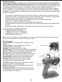
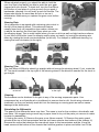
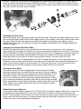
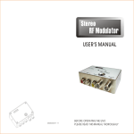
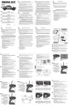
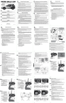
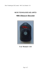
1/36-SCALE ELECTRIC READY-TO-RUN LIFTED TRUCK
Operations Guide
Introduction
Thank you for choosing the Micro-HIGHroller. This guide contains the basic instructions
for operating your new Micro-HIGHroller. While the Micro-HIGHroller is great for firsttime RC drivers, it does require some mechanical experience and parental supervision for
drivers under 14 years of age. It is critical that you read all of the instructions and all
accompanying printed material in order to operate your model correctly and avoid
unnecessary damage. Please take a moment to look them over before running your
model.
DO NOT RUN YOUR MICRO-HIGHroller ON PLUSH CARPET, GRASS OR SAND.
Warning
Although the best materials and components are used, and due to the size of this model, using anything
other than genuine Losi replacement and performance parts specifically designed for the Losi MicroHIGHroller could cause damage.
CONNECT - REGISTER - WIN
Register your product online so we can notify you about the latest option parts, product updates, tech
tips, service bulletins and more. Visit WWW.LOSI.COM and follow the Product Registration link to stay
connected.
For registering your Losi Product you will be automatically entered for a chance to win the Losi Pick Your
Prize Sweepstakes. The winner will be allowed to select a total prize package of $1,000 (retail value)
based on their preference
WWW.LOSI.COM
c 2009 Losi, A Division of Horizon Hobby Inc.
1
Printed 07/09
GETTING STARTED
1. Plug the AC charger into the proper wall receptacle (110V - US version). Plug the battery
pack into the charger and let it charge for 1 hour for the first time. After running, or when the
Micro-HIGHroller slows noticeably, recharge the battery pack for 2-3 hours for a full charge.
2. Your Losi Micro-HIGHroller includes eight (8) AA batteries for your
transmitter. Remove the transmitter battery cover by sliding the cover from
left to right. Install the eight (8) AA batteries into the battery holder. Pay
close attention to the correct direction of the positive (+) and negative (-)
ends as marked in the tray. Once all 8 batteries have been installed, reinstall
the battery cover by sliding it on from right to left.
3. Plug in the battery lead into the speed controller lead and replace the
body. Secure the body with the included body clips.
4. ALWAYS turn on the transmitter first by sliding the switch “ON”. The small red and green
lights above the switch should both light up. If not, please check for low or incorrectly installed
batteries.
5. Once the transmitter has been turned on, turn on the Losi Micro-HIGHroller by sliding the
switch to the “On” position (located on the bottom of the chassis). If the rear wheels turn, adjust
the “TH. Trim” knob located to the lower right of the steering wheel until they stop, to go forward
pull the trigger back. If you should need reverse, wait for the model to stop then push the trigger
forward. When going forward the model should move in a straight line. If not, adjust the “ST.Trim”
so that it tracks in a straight line without having to turn the steering wheel. After you are finished
running, turn the Losi Micro-HIGHroller off FIRST by sliding the switch to the “OFF” position. After
the model has been turned off, turn off the transmitter by sliding the switch to the “OFF” position.
2
Safety Precautions
Age Recommendation: 14 years or over. This is not a toy. This product is not intended for
use by children without direct adult supervision.This is a sophisticated radio controlled model
that must be operated with caution and common sense. Failure to operate your Micro-HIGHroller
in a safe and responsible manner could result in damage to the model and property. The
Micro-HIGHroller is not intended for use by children without direct adult supervision. Losi and
Horizon Hobby, Inc. shall not be liable for any loss or damages, whether direct, indirect, special,
incidental, or consequential, arising from the use, misuse, or abuse of this product or any product
required to operate it.
• This model is controlled by a radio signal that is subject to interference from many sources
outside your control. This interference can cause momentary loss of control so it is advisable
to always keep a safety margin in all directions to avoid collisions.
• Always operate your model in an open area away from cars, traffic and people.
• Never run out into the street for any reason.
• Never run your Micro-HIGHroller with low transmitter batteries.
• Carefully follow the directions and warnings for this and any optional support equipment that
you use.
• Keep all chemicals, small parts and anything electrical out of the reach of children.
Tools and Items You Will Find Handy
• Soft bristle brush for cleaning
• Losi Micro Screwdriver - LOSB1602
• Losi Nutdriver: 4.5mm - LOSA99160
• Small flat blade screwdriver
Note: Use only Losi or other high-quality tools. Use of inexpensive tools can cause damage to
the small screws and parts used on this type of model.
The Transmitter
Steering Wheel: Controls direction (left/right) of the
model.
Transmitter Crystal
Throttle Trigger: Controls speed and direction
(forward/reverse) of the model.
Antenna: Transmits signal to the model.
On/Off Switch: Turns the power on/off for the transmitter.
Indicator Lights: Green (right) light indicates adequate
battery power. Red (left) indicates signal strength.
Steering Wheel
ST. Trim: Adjusts the “hands off” direction of the model.
Antenna
TH. Trim: Adjusts the motor speed to stop at neutral.
ST. Rev
TH. Rev
Steering Rate: Adjusts amount front wheels move
when the steering wheel is turned left and right.
ST. REV: Reverses the function of the steering
when the wheel is turned left or right.
TH. REV: Reverses the function of the speed control
when pulled back or pushed forward.
On/Off Switch
Bottom Cover: Covers and holds the batteries that
Steering Rate
power the transmitter.
Transmitter Crystal: Determines frequency/channel
you transmit on. The receiver must have a matching
frequency/channel to operate
ST. Trim
TH. Trim
Throttle
Trigger
Battery Door
3
The Receiver/Speed Control
Receiver/Electronic Speed Control: Receives
the signal from the transmitter to control the
model’s power and direction of the motor.
Receiver Crystal: Determines which channel it
will receive.
On/Off Switch: Controls power to the receiver.
Antenna Wire: Receives the signal from the
transmitter.
Power Plug: Connects battery pack to the
receiver/speed control.
Steering Servo: Controls steering movement.
Steering Servo Plug: Receiver connection and
power supply.
Motor Plugs: Power connection from the speed
control.
Power On/Off Switch
Receiver Crystal
Steering Servo
Motor Plug
Power Plug
Servo Plug
Changing Frequencies/Channels
The Micro radio operates on 27MHz AM and has 6 different frequencies/channels available.
Simply put, a frequency is like a TV channel. The transmitter you hold in your hand is like the TV
station and the model with the matching crystal is like your TV tuned exclusively to the channel of
the station. The Micro radio is equipped with changeable crystals that allow you to change the
frequency/channel you operate on. This is especially useful when you want to run a group of Losi
Micro’s at the same time. When changing crystals/channels, you must always replace the
crystals as a set with one going in both the transmitter and the receiver in the truck. Each of the 6
different channels are numbered and color-coded. Each set includes a unique crystal for the
receiver marked (Rx) and one from the transmitter marked (Tx). The crystals are changed by
gently pulling them out, later lining up the two pins of each crystal with its socket, then carefully
pushing the new crystals into place. DO NOT force them as damage can occur. If they do not
slide into the socket easily check for bent or misaligned pins.
Crystal Socket
Channel 1
Channel 2
Channel 3
Channel 4
Channel 5
Channel 6
Brown
Red
Orange
Yellow
Green
Blue
26.995MHz
27.045MHz
27.095MHz
27.145MHz
27.195MHz
27.255MHz
(LOSB1094)
(LOSB1095)
(LOSB1096)
(LOSB1097)
(LOSB1098)
(LOSB1099)
Making Adjustments
The following are simple adjustments and easily maintained settings that will assure proper
operation and performance. The Losi Micro-HIGHroller comes from the factory with optimum
settings; we suggest first-time RC drivers leave these as they are and simply maintain them as
necessary. Only after gaining experience should new drivers try experimenting with different
settings.
Slipper Adjustments
The Losi Micro-HIGHroller is equipped with a slipper
device that offers both traction control and protection for
the transmission. The slipper is primarily used to help
absorb sudden impacts on the drivetrain due to landing
big jumps or when using more powerful after-market
motors and/or battery packs. Additionally, it can be used
to smooth out the flow of power to the rear wheels and
limit wheel spin when running on extremely slick
surfaces. Adjustments are made using a 4.5mm nut
driver and adjusting the slipper nut clockwise (to the
right) to reduce the slip or counterclockwise (to the left)
to increase the slip.
4
Decrease Slip
Increase Slip
When adjusted properly, you should be able to hold the
rear tires firmly and barely be able to push the spur gear
forward with your thumb. To track test, turn the Losi-Micro
HIGHroller on and place it on the ground. As you push it
backwards, allowing it to roll freely, punch the throttle. The
slipper should slip no more than an inch or two as it
accelerates. Make sure you replace the gear cover before
running.
Steering Rate
Your transmitter is equipped with a steering rate control to
the left of the steering wheel. This advanced feature,
usually found only on competition-type radios, allows you
to adjust the amount the front tires move when you turn
the steering wheel. This is really helpful when you are on slick as well as high-traction surfaces.
If your Micro-HIGHroller turns too sharply and/or spins out easily, try turning the steering rate
down by rotating the knob counterclockwise (to the left). For sharper or additional steering, try
turning the knob clockwise (to the right).
“ Less Rate”
“ More Rate”
“ Less Rate”
Steering Trim
The Losi Micro-HIGHroller should go straight without turning the steering wheel. If not, rotate the
ST.Trim knob located to the top right of the steering wheel in the direction needed for the truck to
go straight.
Adjust steering trim
to the left.
Adjust steering trim
to the right.
Cleaning
Performance can be hindered if dirt gets in any of the moving suspension parts. Use
compressed air, a soft paintbrush or toothbrush to remove dust or dirt. Avoid using solvents or
chemicals, as they can actually wash dirt into the bearings or moving parts as well as cause
damage to the electronics.
Rebuilding the Differential
The gears in the differential wear over time. The same is true for the outdrives, driveshafts, and
rear axles. We suggest using a small rag or paper towel to lay out the parts you remove to make
it easier to reassemble.
1) Unplug the motor. 2) Remove the gear cover (three screws). 3) Remove the motor guard
screws at the top of the transmission and the two lower extreme rear bottom of the chassis. 4)
Remove the screw that attaches the rear shock tower to the transmission and the 4 long flat
head screws at the bottom of the chassis that hold the gearbox in place and slide it out of the
5
chassis. 5) Remove the left side of the gearbox by removing the three screws. 6) Follow Figure 1
below to rebuild the differential (Use LOSA3066 Grease). 7) Once the differential has been rebuilt,
assemble the transmission by following the steps in the reverse order. Be sure to use the screws in
the same location that they were removed.
1
3
2
2
1
1
3
Changing the Spur Gear
Remove the gear cover by removing the three small screws. Remove the slipper adjustment nut at
the end of the slipper shaft and all of the slipper parts on the outside of the spur gear as well as the
old gear. Place the new spur gear into position and replace the slipper parts. After you have
changed the spur gear, you will have to adjust the slipper as described in the “Slipper Adjusment”
section on page 3.
Changing the Pinion Gear/Gear Ratio
Before you change the pinion, ask yourself why you are doing it. In general, if you change to a
larger pinion the top speed will improve, but you will see less acceleration and run time. This would
only be advisable for really long track layouts with few tight turns. Changing to a smaller pinion will
give you quicker acceleration and possibly a bit longer run time but a little less top speed. This
would be good for short layouts or when running faster motors. The pinion that is on the
Micro-HIGHroller offers the best balance of both. To change the pinion, remove the gear cover,
loosen the motor screws and slide the motor back. Use a small flat head screwdriver between the
motor plate and pinion gear to push the gear off. Place the new pinion on the end of the motor
shaft and press the new pinion gear into the same position as the one removed.
Setting the Gear Mesh
The motor screws should be slightly loose. Slide the motor forward
allowing the pinion gear to mesh with the spur gear. Snug (not tighten)
the bottom motor screw and try rocking the spur back and forth. There
shoud be a slight bit of movement before the motor is forced to turn
over. If not, pull the top of the motor back slightly and recheck. If there
is too much slop between the gears, push the top of the motor forward.
When set properly, the wheels can be spun forward freely with very little
noise. Make sure to tighten both motor screws and replace the gear
cover before running.
Radio Replacement/Service
If you have a radio problem please call 1-877-504-0233 for product support. Most likely, unless you
have gotten the components wet, the service technician can help you fix the problem over the
phone. If the problem is more severe, you may be asked to send in your vehicle and transmitter. In
some cases, like a broken servo or a speed control that has failed due to getting wet, your local
dealer can sell you the replacement component.
6
Replacing the Steering Servo
1. Unplug all wires, remove receiver crystal and 4 screws pictured in Figure 1. (Be sure to note the
locations of all screws and sizes.)
2. Remove the 2 screws pictured in Figure 2, and place the PC board to the side.
3. Remove the 4 screws pictured in Figure 3. Remove the servo cover.
4. Slide the servo out from the chassis as shown in Figure 4.
5. Replace with new servo and be sure to place the tip of the servo saver into the slot of the
steering bellcrank.
6. Reverse instruction order to complete servo installation.
Figure 1.
Figure 2.
Figure 4.
Figure 3.
Troubleshooting Guide
Doesn’t operate: Battery not charged, no crystal in receiver, no crystal in transmitter, receiver
switch not “on”, transmitter not “on”, or low battery.
Motor runs but rear wheels don’t move: Pinion not meshing with spur gear or pinion spinning on
motor shaft or slipper too loose or transmission gears stripped.
Steering doesn’t work: Servo plug not in receiver or servo gears or servo motor damaged.
Motor doesn’t run: Motor plugs loose or motor wire broken or ESC damaged.
ESC gets hot: Motor over-geared or driveline bound up.
Poor run time and/or sluggish acceleration: Batteries low (need longer charge), slipper clutch
slipping too much, motor worn out, driveline bound up, or wheel and axle bushing worn.
Poor range/glitching: Transmitter batteries low, transmitter antenna loose, vehicle battery low,
loose plugs or wires.
Slipper won’t adjust: Slipper adjustment nut worn out or spur gear face worn down.
Wheels wobble/shake: Bushing worn out.
7
SERVICE/REPAIR
If you have any problems other than those covered in the troubleshooting section of this operation
guide, please call the Horizon Hobby Product Support line at 1-877-504-0233. They will be able to
give you specific additional attention and instruct you as to what needs to be done.
Horizon Hobby Customer Service
4105 Fieldstone Rd.
Champaign, IL, 61822 USA
1-877-504-0233 www.horizonhobby.com
email: [email protected]
Warranty Period
Exclusive Warranty- Horizon Hobby, Inc., (Horizon) warranties that the Products purchased (the
“Product”) will be free from defects in materials and workmanship at the date of purchase by the
Purchaser.
Limited Warranty
(a) This warranty is limited to the original Purchaser (“Purchaser”) and is not transferable. REPAIR
OR REPLACEMENT AS PROVIDED UNDER THIS WARRANTY IS THE EXCLUSIVE REMEDY
OF THE PURCHASER. This warranty covers only those Products purchased from an authorized
Horizon dealer. Third party transactions are not covered by this warranty. Proof of purchase is
required for warranty claims. Further, Horizon reserves the right to change or modify this warranty
without notice and disclaims all other warranties, express or implied.
(b) Limitations- HORIZON MAKES NO WARRANTY OR REPRESENTATION, EXPRESS OR
IMPLIED, ABOUT NON-INFRINGEMENT, MERCHANTABILITY OR FITNESS FOR A PARTICULAR PURPOSE OF THE PRODUCT. THE PURCHASER ACKNOWLEDGES THAT THEY ALONE
HAVE DETERMINED THAT THE PRODUCT WILL SUITABLY MEET THE
REQUIREMENTS OF THE PURCHASER’S INTENDED USE.
(c) Purchaser Remedy- Horizon’s sole obligation hereunder shall be that Horizon will, at its option,
(i) repair or (ii) replace, any Product determined by Horizon to be defective. In the event of a defect,
these are the Purchaser’s exclusive remedies. Horizon reserves the right to inspect any and all
equipment involved in a warranty claim. Repair or replacement decisions are at the sole discretion
of Horizon. This warranty does not cover cosmetic damage or damage due to acts of God,
accident, misuse, abuse, negligence, commercial use, or modification of or to any part of the
Product. This warranty does not cover damage due to improper installation, operation, maintenance, or attempted repair by anyone other than Horizon. Return of any goods by Purchaser must
be approved in writing by Horizon before shipment.
Damage Limits
HORIZON SHALL NOT BE LIABLE FOR SPECIAL, INDIRECT OR CONSEQUENTIAL DAMAGES, LOSS OF PROFITS OR PRODUCTION OR COMMERCIAL LOSS IN ANY WAY CONNECTED WITH THE PRODUCT, WHETHER SUCH CLAIM IS BASED IN CONTRACT, WARRANTY, NEGLIGENCE, OR STRICT LIABILITY. Further, in no event shall the liability of Horizon
exceed the individual price of the Product on which liability is asserted. As Horizon has no control
over use, setup, final assembly, modification or misuse, no liability shall be assumed nor accepted
for any resulting damage or injury. By the act of use, setup or as¬sembly, the user accepts all
resulting liability.
If you as the Purchaser or user are not prepared to accept the liability associated with the use of
this Product, you are advised to return this Product immediately in new and unused condition to the
place of purchase.
Law: These Terms are governed by Illinois law (without regard to conflict of law principals).
8
Safety Precautions
This is a sophisticated hobby Product and not a toy. It must be operated with caution and common
sense and requires some basic mechanical ability. Failure to operate this Product in a safe and
responsible manner could result in injury or damage to the Product or other property. This Product is
not intended for use by children without direct adult supervision. The Product manual contains
instructions for safety, operation and maintenance. It is essential to read and follow all the instructions and warnings in the manual, prior to assembly, setup or use, in order to operate correctly and
avoid damage or injury.
Questions, Assistance, and Repairs
Your local hobby store and/or place of purchase cannot provide warranty support or repair. Once
assembly, setup or use of the Product has been started, you must contact Horizon directly. This will
enable Horizon to better answer your questions and service you in the event that you may need any
assistance. For questions or assistance, please direct your email to
[email protected], or call 877.504.0233 toll free to speak to a service technician.
Inspection or Repairs
If this Product needs to be inspected or repaired, please call for a Return Merchandise Authorization
(RMA). Pack the Product securely using a shipping carton. Please note that original boxes may be
included, but are not designed to withstand the rigors of shipping without additional protection. Ship
via a carrier that provides tracking and insurance for lost or damaged parcels, as Horizon is not
responsible for merchandise until it arrives and is accepted at our facility. A Service Repair
Request is available at www.horizonhobby.com on the “Support” tab. If you do not have internet
access, please include a letter with your complete name, street address, email address and phone
number where you can be reached during business days, your RMA number, a list of the included
items, method of payment for any non-warranty expenses and a brief summary of the problem. Your
original sales receipt must also be included for warranty consideration. Be sure your name, address,
and RMA number are clearly written on the outside of the shipping carton.
Warranty Inspection and Repairs
To receive warranty service, you must include your original sales receipt verifying the
proof-of-purchase date. Provided warranty conditions have been met, your Product will be
repaired or replaced free of charge. Repair or replacement decisions are at the sole discretion of
Horizon Hobby.
Non-Warranty Repairs
Should your repair not be covered by warranty the repair will be completed and payment will
be required without notification or estimate of the expense unless the expense exceeds 50%
of the retail purchase cost. By submitting the item for repair you are agreeing to payment of
the repair without notification. Repair estimates are available upon request. You must include this
request with your repair. Non-warranty repair estimates will be billed a minimum of ½ hour of labor.
In addition you will be billed for return freight. Please advise us of your preferred method of
payment. Horizon accepts money orders and cashiers checks, as well as Visa, MasterCard,
American Express, and Discover cards. If you choose to pay by credit card, please include your
credit card number and expiration date. Any repair left unpaid or unclaimed after 90 days will be
considered abandoned and will be disposed of accordingly. Please note: non-warranty repair is
only available on electronics and model engines.
Electronics and engines requiring inspection or repair should be shipped to the following address:
Horizon Service Center
4105 Fieldstone Road
Champaign, Illinois 61822 USA
All other Products requiring warranty inspection or repair should be shipped to the following
address:
Horizon Product Support
4105 Fieldstone Road
Champaign, Illinois 61822 USA
Please call 877-504-0233 with any questions or concerns regarding this product or warranty.
9
United Kingdom
Electronics and engines requiring inspection or repair should be shipped to the following
address:
Horizon Hobby UK
Units 1-4 Ployters Rd
Staple Tye, Harlow
Essex
CM18 7NS
United Kingdom
Please call +44 (0) 1279 641 097 or email us at [email protected] with any questions or concerns regarding this product or warranty.
Germany
Electronics and engines requiring inspection or repair should be shipped to the following
address:
Horizon Technischer Service
Hamburger Str. 10
25335 Elmshorn, Germany
Please call +49 4121 46199 66 or email us at [email protected] with any questions or concerns regarding this product or warranty.
CE Compliance Information for the European Union
Instructions for Disposal of WEEE by Users in the European Union
This product must not be disposed of with other waste. Instead, it is the user’s responsibility
to dispose of their waste equipment by handing it over to a designated collection point for the
recycling of waste electrical and electronic equipment. The separate collection and recycling
of your waste equipment at the time of disposal will help to conserve natural resources and
ensure that it is recycled in a manner that protects human health and the environment. For
more information about where you can drop off your waste equipment for recycling, please
contact your local city office, your household waste disposal service or where you purchased
the product.
10
Declaration of Conformity
(in accordance with ISO/IEC 17050-1)
No. HH20090816
Product(s):
Item Number(s):
LOS 1/36 Micro-HIGHroller
LOSB0237
Equipment class:
1
The object of declaration described above is in conformity with the requirements
of the specifications listed below, following the provisions of the European
R&TTE directive 1999/5/EC:
EN 300-220
EN 301 489-3
Technical requirements for Radio equipment.
General EMC requirements
Signed for and on behalf of:
Horizon Hobby, Inc.
Champaign, IL USA
Aug 16, 2009
Steven A. Hall
_____________________________________
Vice President
International Operations and Risk Management
Horizon Hobby, Inc.
11
WWW.LOSI.COM
Horizon Hobby, Inc.
4105 Fieldstone Road
Champaign, IL 61822
12