1
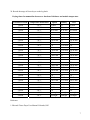
Electron Microscopy Centre
Title:
STANDARD PROCEDURES TO USE THE TISSUE
DRYER
Equipment: Edwards Tissue Dryer Model ETD4
Revision:
1.0
Effective Date: 12/21/2005
Author:
X. Yang
1
Warning!
Before you attempt to operate this equipment for the first time, please make sure you
are aware of the precautions that you must take to ensure your own safety.
Working Environment
Do not use electrical equipment in:
• Rain or excessive moisture environment
• The presence of flammable or explosive gases
The equipment is not designed to be water or splash proof, or to be used in area
where there are flammable or explosive gases or fumes.
2
Standard Procedures to Use the Tissue Dryer
The purpose of freeze dryer is to remove water from a frozen material by sublimation so to
preserve biological materials. Sensitive media such as tissues can be dried and preserved with
very low moisture contents. Reconstruction of freeze dried products can be achieved by adding
distilled or sterile water.
Checkouts before a Drying run:
1.
Thermo-electric module cooling check
1.1. Having connected the unit to the electrical and water supplies, switch on mains supply.
Mains electricity indicators on the front panel should light.
1.2. Ensure all valves are closed and the variable element controller is set at the zero position.
1.3. Turn on water supply
1.4. Fill the desiccant tray with fresh molecular sieve and place in position on the base plate
1.5. Place the chamber in position on the base plate
1.6. Depress the buttons marked “RP”, “element” and “cold” on the temperature selector
switch and turn the variable element controller in a clockwise direction to position 7. The
temperature should start falling to -50 ºC.
2.
Vacuum check
2.1. Switch on the rotary pump by depressing the switch button on the front panel marked
“RP”
2.2. Switch the chamber isolation valve from isolation to pump position on the front panel.
2.3. The pressure should fall to 10-2 mbar within 6 minutes.
Note: The pump-down time can only be expected with a clean empty chamber containing
molecular sieve. The first pump-down after a long exposure to atmosphere will be
prolonged due to the degassing of vapour from the surface of the system. Subsequently
pump-down times should be shorter.
2.4. If the above pumping performance cannot be obtained, switch off the element and turn the
variable element controller knob to zero position. Depress the “OFF” button on the front
panel and contact EMC staff immediately.
The following steps only apply to advanced users only.
2.5. Switch the chamber isolation valve from pump to isolation position and open the air
admittance valve to vent the chamber.
3
2.6. Open the gas-ballast valve on the front panel and allow the pump to operate on full gas
ballast for about 1 hour. This operation will clean the pump oil if contaminated and
improve the subsequent performance.
2.7. Repeat the original vacuum test after gas ballasting has been completed. Close the
chamber air admittance valve. Depress the “element” and “cold” temperature selector
switches and turn the variable controller to maximum.
2.8. When the temperature reaches -40ºC open the chamber isolation valve and repeat test as
2.7.
2.9. If the correct pump-down times still cannot be obtained, check the system for leaks.
3.
Thermoelectric Module heating check
3.1. With the chamber under vacuum and the thermoelectric element cooled to about -58 ºC,
turn the variable element controller to zero position.
3.2. Depress the “element” and the “heat” button on the temperature selector switch.
3.3. Turn the variable element controller in a clockwise direction. Heating will now take place
and with the controllers in a fully clockwise position, the temperature will rise to
approximately +60 ºC in about 12 minutes.
Note: If the variable element controller has been preset to certain value for cooling down
purpose, the heat function will not start. You will have to turn it counterclockwise to zero
position then reset it to the desired value.
Operation of Freeze Dryer:
1. Check the waterline is proper connected.
2. Check both air admit and gas ballast valves are closed. If not, close the valves
3. Check the variable element controller is set at zero position. If not, set to zero.
4. Ensure the tray within the chamber is filled with fresh molecular sieve.
Note: When fresh desiccant is used it is advisable to allow the surface to absorb a small
quantity of atmospheric moisture; this will prevent its subsequent migration in the vacuum
system and possible contamination of the specimen.
4
5. Turn on cooling water valve mounted on the wall: turn the valve anticlockwise and check that
sufficient water flows. The minimum flow required is 1.0 L/min at a maximum pressure of 4.2
kgf/cm2.
6. Check both cylinder valve (fully clockwise) and regulator valve (anticlockwise) are closed.
7. Turn on argon: slowly turn the cylinder valve clockwise until there is a reading at the first
meter. Slowly turn the regulator clockwise until the second meter is reading about 5 psi.
Note: Please refer to a separate document for detailed operation procedures for handling high
pressure gas cylinder.
8. Switch on the power by depressing both green buttons marked “mains” and “~”.
9. Switch the chamber isolation valve to “pump”.
10. Switch on the rotary pump by depressing the button marked “RP”. The rotary pump will start
immediately and the needle of the vacuum gauge will register falls. If the needle is falling
below 0.1 mbar, it indicates that there are no major leaks in the system. If the needle could not
fall under 0.1 mbar for a quite while, contact the EMC staff for support or refer to the vacuum
check section.
11. Depress the buttons marked “element” and “cold” on the temperature selector switch and turn
the variable element controller to the desired value. If not sure, a value of “7” is always a good
start point. The temperature on the base plate should start falling down to a certain value
depending on the setting.
12. Prepare and freeze the specimen by quenching it in R12 refrigerant or iso-pentane cooled by
liquid nitrogen.
13. Switch the chamber isolation valve to “isolation” and open the air admittance valve by turning
it counter-clockwise slowly to vent the chamber with dry Argon gas.
14. When the chamber is vented, open the metal cover and transfer the frozen specimen onto the
base plate.
Note: During the transferring, please remember to wear power free gloves provided to avoid
potential contamination to the specimen and vacuum chamber.
Caution: A cold burn could result is the cold plate or the liquid nitrogen is in contact with bare
skin when transferring the frozen specimen.
5
15. Replace the chamber cover in position. Close the air admittance valve and switch the chamber
isolation valve to “Pump”.
Caution: the air admittance valve and gas ballast valve and needle valves, which is very
sensitive to the force. When operating with such valve, please be gentle. The treads on air
admittance valve have been found to be worn out.
16. The tissue should start to dry.
Note: The drying times for individual specimen are different depending on the tissue type,
frozen temperature and thickness of the tissue. Please refer to available references.
Practical tests might also have to be contacted in order to obtain more relevant
information.
Examples of drying time are given at the end of the manual.
17. When the specimen is dry, depress the “cold” button and set the variable element controller
back to zero position. The specimen should start to warm up to room temperature.
18. Close the cylinder valve while the regulator valve remains on.
19. Switch the isolation valve to “isolation” and slowly open the air admittance valve to vent the
chamber with residue dry argon gas. By doing this, user not only vents the work chamber but
also release the residue high pressure argon gas remained in the regulator and tubing.
Caution: if the valve is opened too quickly, the specimen may be blown from the plate by the
inrush of air to the chamber.
20. Remove the work chamber and top plate (with powder free gloves). Transfer the specimen to
vapour fixative to embedding medium as desired.
21. Replace work chamber and top plate. Close the air admittance valve (fully clockwise) and
switch the chamber isolation valve to “pump” so the chamber could maintain at vacuum.
22. Switch the isolation valve to “isolation” after evacuation. Switch off rotary pump and power
by depressing “RP” and two green buttons.
23. Close the regulator valve by turning the knob counter-clockwise when regulator meters read
zero.
6
24. Record the usage of freeze dryer on the log book.
Drying times for mammalian tissues as a function of thickness and module temperature
Thickness of tissue
Temperature maintained
Spleen
Kidney
Liver
1.0 mm
2.0 mm
3.0 mm
4.0 mm
-10 ºC
-10 ºC
-10 ºC
-10 ºC
55 min
1h
3h 30 min
1h
2h
3h 30 min
45 min
1h
3h 30 min
1.0 mm
2.0 mm
3.0 mm
4.0 mm
-20 ºC
-20 ºC
-20 ºC
-20 ºC
1h
2 h 30 min
4h
5h
1 h 10 min
3h
4h
5 h 30 min
45 min
1 h 30 min
4h
5h
1.0 mm
2.0 mm
3.0 mm
4.0 mm
-30 ºC
-30 ºC
-30 ºC
-30 ºC
1 h 20 min
3h
3 h 45 min
1 h 20 min
3h
4h
1 h 20 min
3h
3 h 45 min
1.0 mm
2.0 mm
3.0 mm
4.0 mm
-40 ºC
-40 ºC
-40 ºC
-40 ºC
2h
3 h 45 min
4 h 30 min
6 h 30 min
2h
3 h 45 min
4 h 30 min
6 h 45 min
2h
3 h 45 min
4 h 30 min
6 h 30 min
1.0 mm
2.0 mm
3.0 mm
4.0 mm
-50 ºC
-50 ºC
-50 ºC
-50 ºC
3h
4 h 45 min
6 h 15 min
3h
4 h 45 min
6 h 15 min
3h
4 h 45 min
6 h 15 min
1.0 mm
2.0 mm
3.0 mm
4.0 mm
-60 ºC
-60 ºC
-60 ºC
-60 ºC
5 h 30 min
8h
overnight
overnight
5 h 30 min
8h
overnight
overnight
5 h 30 min
8h
overnight
overnight
Reference:
1. Edwards Tissue Dryer User Manual. Edwards,1983
7