1
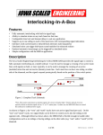
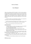
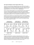
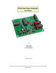
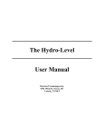
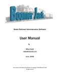
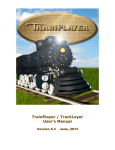
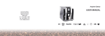
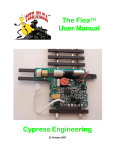
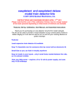
CKT-IRSENSE v3 User Manual
Features
•
•
•
•
•
•
Small size (0.25" x 2.25")
No adjustment needed
Simple, discrete under-track installation
Variable release time up to 23 seconds (or 23 minutes with Long Delay option)
Two opposite polarity outputs (40V / 250mA capable)
Tolerant of background lighting conditions (no false triggering)
Applications
•
•
•
•
•
•
•
•
Activate grade crossing signals
Trigger a sound event using a CKT-SQUEAL sound player
Simulating a spring switch using an MRServo switch machine
Control an automatic interchange
Block detection for signal systems
Occupancy detection on hidden tracks
End-of-track indication in hidden staging yards
C/MRI track occupancy inputs
Operation
The CKT-IRSENSE is an inexpensive reflective infrared proximity sensor, designed primarily for model
railroad use. At the top of the device are two small lenses - one emits a series of infrared pulses, which
are then reflected by objects into the other lens, a receiver. By measuring the intensity of the returned
pulses, the sensor can detect the presence of and distance to an object. The device also automatically
compensates for background lighting, eliminating false triggers.
1
Mechanical Installation
The detector is designed to be installed up through the benchwork in a 3/8 inch (10 mm) hole. To install
in existing track, first drill a 1/16” pilot hole between the ties. Then, from the bottom, drill a 3/8” hole
up toward the track, using the pilot hole you just drilled as a guide. Work slowly and be very careful to
not damage the ties (you might want to remove a couple of ties first and reinsert them after drilling the
hole). Once the sensor is installed, be sure that both lenses are clear to shine up between any ties or
ballast.
The module is not naturally water resistant, so be careful when ballasting. Some amount of water
resistance can be added by coating everything (other than the lenses) with liquid electrical tape or
similar sealant. Be very careful not to cloud or cover the detector lenses.
The sensor can be secured in the hole using a variety of methods such as hot glue or by using a
mounting bracket. See the Iowa Scaled Engineering website for more details and some example
mounting brackets.
1/16" pilot hole
3/8" mounting hole
2
Electrical Connections
The CKT-IRSENSE needs 5-24 volts of clean direct current (DC) power to operate. Noisy power
supplies may cause issues with detection, and supply voltages exceeding 25VDC may damage the
device. The red wire should be connected to the positive side of the power supply and the black wire to
the negative.
Two outputs are provided, both of which are “open drain” (also known as “open collector”). This means
that they act like a switch to the ground / negative lead. When an output is “active”, it will conduct
current to ground. When an output is “inactive”, it will act like an open circuit and not pass current at
all. Each output line can handle a maximum of 0.25 amps, and should be exposed to no more than a
40VDC supply. The white output is active when the sensor is detecting an object. The blue output is
active when the sensor is not detecting an object.
Low when object detected
Low when object NOT detected
5V - 24V
GND
Release Time Adjustment
If a logic level output is desired, use a 4.7k-10k ohm resistor to pull up the output to the positive supply.
To directly drive an LED, connect a current-limiting resistor in series with the LED and connect the
LED cathode to the CKT-IRSENSE output. Since the outputs are open drain, multiple CKT-IRSENSE
outputs can be connected in parallel combining them into one signal. Some example connections are
shown below.
3
Activation Time
The activation time is preset to 0.1 seconds. The outputs will indicate that an object has been detected if
the object is present over the sensor for 2 consecutive readings spaced 100ms apart. This helps
eliminate errant readings. As a consequence of this, though, there will be a slight (0.1s) delay for an
object being detected. For most model railroad applications, this is not an issue. If longer (or shorter)
activation times are required, we can provide custom programmed devices. Please contact us with your
requirements.
Release Time
The release time is preset to 0.1 seconds. The outputs will indicate that an object is no longer detected if
the object is not present over the sensor for 2 consecutive readings spaced 100ms apart. This can be
used to debounce the detector outputs to stop the outputs from toggling, for example, in the spaces
between rolling stock as it travels over the sensor.
Longer release times are available by connecting a resistor between the yellow wire and ground (black
wire) based on the following table.
Resistor
Delay
Resistor
Delay
Resistor
Delay
100k
0.1s
27k
4.4s
7.5k
12.1s
82k
0.3s
24k
5s
6.8k
12.7s
75k
0.5s
22k
5.5s
6.2k
13.3s
68k
0.8s
20k
6s
5.6k
13.9s
62k
1s
18k
6.6s
4.7k
14.9s
56k
1.4s
16k
7.3s
3.9k
15.9s
51k
1.7s
15k
7.7s
3k
17.2s
47k
2s
13k
8.6s
2.4k
18.1s
43k
2.3s
12k
9.1s
1.8k
19.2s
39k
2.7s
11k
9.7s
1.3k
20.1s
36k
3.1s
10k
10.3s
910
21s
33k
3.4s
9.1k
10.9s
430
22s
30k
3.9s
8.2k
11.6s
33
23s
Note: The times listed above are for the Normal Delay option. A Long Delay option is also available
where the delay times are 60x longer (e.g. 20k = 6 minutes).
4
Sensing Distance
The CKT-IRSENSE is pre-calibrated to a typical detection range (~1.5”) and needs no user adjustment
for most applications. However, the detection distance will vary based on the reflectivity of the object
being sensed. If other ranges are needed, contact us for custom programmed devices. The detection
range can be adjusted from approximately 0.5” to 3”.
5
Low when object detect
Low when object NOT d
Simulating a Spring Switch
Spring switches are used by some prototype railroads to save the crew from having to re-align the switch
points after passing through the switch. The switch is sprung in one direction (typically the mainline),
Release Time Adjustme
allowing any train to pass through the switch from the frog end without manually aligning the points.
When entering the mainline from a siding, this allows the train to continue on its way without having to
realign the points to the main – the spring action takes care of this automatically. Modeling this unique
feature can be easily accomplished with an IR sensor and switch machine.
This application uses a CKT-IRSENSE reflective infrared proximity detector to detect the approach of a
train on the diverging route. Normally, the points are aligned to the main track. When a train is
detected on the diverging route, the IR sensor shorts its output to GND, toggling the control input to an
MRServo switch machine that controls the turnout, causing the points to align with the diverging route.
As long as the IR sensor remains covered, the points remain set for the diverging route. Once
uncovered, there is a programmable delay (up to 23 seconds) before the output of the IR sensor is
released. This allows time for the train to clear the points before they are automatically set back to the
main route.
CKT-IRSENSE
Not Connected
GND
8V - 14V
Delay Adjust
Resistor
MRServo Control Board
Manual Control Switch
6
Automatic Interchange
An automated interchange track, similar to the one described in the September 2006 issue of Model
Railroader, can be assembled using a CKT-IRSENSE and a relay module (ACC-RELAY1). The IR
sensor is placed near the switch end of the interchange track. When the sensor is covered (by a piece of
rolling stock, for example), the blue output line is released, causing the relay module (configured to
activate with a low input) to be in the normal position. The normally-open (NO) contacts of the relay
cut track power.
After a train picks up the cars covering the sensor, the blue output line then pulls low. This causes the
relay to activate, closing the circuit between the COM and NO terminals. This applies power to the
track, causing a locomotive to push another cut of cars forward until they cover the sensor. At that point,
track power is once again cut and the cars are available to be picked up by the next train.
A resistor can be connected between the yellow Release Time Adjustment wire and GND (black wire) to
delay the time between the cars being picked up and when the locomotive begins to push the next cut of
cars. The Long Delay option on the CKT-IRSENSE can be useful for this application.
CKT-IRSENSE
Not Connected
DCH
NC
12V
L
COM
DC+
IN
NO
GND
ACC-RELAY1 (12V Option)
Track
Power
7
Open Design
Iowa Scaled Engineering is committed to creating open designs that users are free to build, modify,
adapt, improve, and share with others.
Hardware
The design of the CKT-IRSENSE hardware is open source hardware, and is made available under the
terms of the Creative Commons Attribution-Share Alike v3.0 license, a copy of which is available from:
http://creativecommons.org/licenses/by-sa/3.0/
Design files can be found on the Iowa Scaled Engineering website:
http://www.iascaled.com/store/CKT-IRSENSE
Firmware
The official Iowa Scaled Engineering firmware for the CKT-IRSENSE is free software: you can
redistribute it and/or modify it under the terms of the GNU General Public License as published by the
Free Software Foundation, either version 3 of the License, or (at your option) any later version. A copy
of the GNU GPL can be found at: http://www.gnu.org/licenses/gpl.html
New firmware can be flashed into the CKT-IRSENSE through J1. The six land pads implement the
standard AVR 6-pin ISP header on a connector compatible with the Tag-Connect TC2030 cable.
Stable releases of firmware and source code can be found on the Iowa Scaled Engineering website:
http://www.iascaled.com/store/CKT-IRSENSE
Iowa Scaled Engineering
http://www.iascaled.com/
8
[email protected]