1
Model SDT-Ex
Dewpoint Transmitter
Instruction Manual
Model SDT-Ex
Dewpoint Transmitter
Instruction Manual
Unpacking your Shaw Moisture Meters Model SDT-Ex
Please examine the SDT-Ex package for any damage or mishandling. If any damage is evident
please notify the carrier and the Shaw Moisture Meters representative from where this unit was
purchased.
You should have received: (if ordered)
1 SDT-Ex 4-20mA Dewpoint Transmitter
1 Connecting cable (of the length specified on your order) or 2m as standard.
1 SDT Special Sensor holder
1 Instruction Manual
1 Pressure Dewpoint Circular Calculator
If anything is missing please contact your distributor immediately.
Issue 1.0 12/2008
1937 SDT-Ex User Manual
Index
1
Overview ..............................................................................................................1
1.1
2
Installing the SDT-Ex in a Air/Gas Sampling System......................................3
2.1
2.2
2.3
2.4
2.5
3
Piping Installation Schematic ................................................................................................ 3
Piping Schematic Component Index ..................................................................................... 4
Installing and Commissioning the Model SDT-Ex Transmitter .............................................. 4
Wiring the SDT-Ex ................................................................................................................ 5
Connector Pins ..................................................................................................................... 5
Normal Operation ................................................................................................6
3.1
4
Gas Compatibilities............................................................................................................... 2
Analogue 4-20mA Mode (3-wire) .......................................................................................... 6
Autocal .................................................................................................................6
4.1
4.2
4.3
Pre-conditioning the transmitter ............................................................................................ 7
Adjusting the Autocal ............................................................................................................ 7
Completing the autocal ......................................................................................................... 7
5
Faults/Errors ........................................................................................................7
6
SDT-Ex Specification ..........................................................................................8
7
Appendix A – SDT-Ex and PR5104BB2A Signal Isolator Connection
8
Appendix B – PR5104BB2A to SDT-Ex Connections
9
Appendix C – SDT-Ex with Connector, General Arrangement
10 Appendix D – Transmitter Holder, General Arrangement
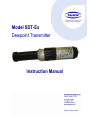
1 Overview
The Shaw Moisture Meters Model SDT-Ex is a 3 wire 4-20mA loop powered transmitter, used
for continuous measurement of moisture in a process gas or compressed air. The Model SDTEx transmitter can be factory configured to output a 4-20mA linear signal for any of the
following moisture units: - ºC or ºF dewpoint, ppm(v), ppb(v), g/m3, and lb/MMSCF.
The ultra high capacitance Shaw sensing element is long lasting and offers excellent sensitivity,
repeatability and response speed. Each unit is calibrated, traceable to International Humidity
Standards, and is supplied with a Certificate of Calibration guaranteeing accuracy to ± 2ºC dew
point.
The transmitter also incorporates an Automatic Calibration (AUTOCAL) feature, which allows
the user to carry out field calibration / span check. The AUTOCAL feature is operated by means
of a small potentiometer built into the transmitter body. To avoid accidental corruption, the
potentiometer is covered by a weatherproof seal in normal use.
The RISC microprocessor circuitry of the Model SDT-Ex transmitter allows high resolution with
advanced self-diagnostics for fault conditions. It also enables periodic re-calibration of the
moisture sensor, storing calibration data within the fully self-contained unit. Loop powered, by a
7v to 28v dc source. The Model SDT-Ex transmitter will provide the user with a linear 4-20mA
signal over the chosen range.
The mechanics of the Model SDT-Ex transmitter have been designed to cope with extreme
environmental conditions. The rugged stainless steel construction and anodised aluminium
offers protection to IP66 (NEMA4X), with the transmitter electrical connections made via secure
industrial type connector (size C, DIN EN 175301).
The SDT-Ex transmitter can withstand 35,000 kPa (350bar) maximum pressure and by
employing low resistance cable, the transmitter can be located at significant distances, in
excess of 1000 meters, from the data collection point.
Designed with the operator in mind, for reliable and accurate measurements, the Model SDTEx is extremely easy to install and operate, requiring little or no maintenance.
1
1.1 Gas Compatibilities
The Model SDT-Ex sensing elements are Al2O3 and therefore suitable for many different
industrial and research applications. Most gases can be checked for their moisture content
with no need for the calibration to be altered when changing between different gases, as the
sensor operates only with reference to the water vapour content. However, some gases must
be avoided, as they are not compatible with the material used in the construction of the sensor.
Ammonia (NH3) and chlorine (Cl) must be avoided at all times, even in small quantities.
Hydrogen chloride (HCl) also attacks the sensors very quickly. Some, less aggressive, acidic
gases, such as sulphur dioxide (SO2), can be monitored, as long as the moisture content is
low, generally less than 100ppm(v). If in doubt, please ask your supplier.
Sulphur hexaflouride (SF6) has no effect on the sensor. If the gas has been exposed to arcing,
however, it is possible that various acidic species will have been formed that will corrode the
sensor. When testing SF6 that may have been arced, therefore, an acidity test should be
carried out first; if the gas proves to be acidic then the moisture test should not be carried out.
It is strongly recommended that the sample should not contain particulate matter, oil or other
heavy hydrocarbon condensate. If these components contaminate the sample system and/or
the measuring sensor, the system response time will be lengthened, although the sensor
calibration will not be effected.
2
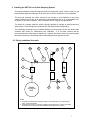
2 Installing the SDT-Ex in a Air/Gas Sampling System
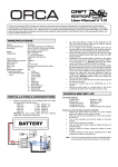
The piping installation schematic diagram shows all components, which could be used in a gas
measurement application although not all items shown will be required for every installation.
The flow rate, although not critical, should be low enough to avoid abrasion to the sensor
surface without being so low as to extend the system response time to an unacceptable level.
In general, a flow rate of between 2 and 3 litres/min at NTP will give the right balance.
The sensor is a variable capacitor, which is directly affected by changes in partial pressure of
water vapour. These changes are proportional to the dew/frost point temperature.
The measuring transmitter can be installed directly into the process line but this does create
problems with access for maintenance and calibration. It is for these reasons that we
recommend that the transmitter be installed in a bypass, fast loop or total loss sample system
where the transmitter is accessible without interrupting the main process flow line.
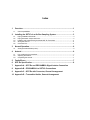
2.1 Piping installation Schematic
4A
5
7
6
10
11
P
2
3
1
MA IN
PROCESS
LINE
8
4B
9
NOTES
a. The sample po in t sh ou ld b e on the upper surface of a horizontal pipe or on a vertical se ction
of pipe , wh ere ever possible.
b. The sample tube sho uld ru n, continually, upwards from the sample point. If this is not po ssible
an insp ectio n p ort o r drain tap should be installed at the lowest point in the syste m.
3
2.1 Piping Schematic Component Index
1) Sample Isolation Valve - This is a recommended item as it allows access to the sample system
without interrupting the main process line.
2) Sample Tube – This should be stainless steel for dry air or gas applications but copper or carbon
steel can be used where wetter gases are to be measured. If any section of the sample tube must
be flexible then PTFE should be used. In most cases, 3mm OD (1/8”) is sufficient as it provides
good system response time within minimum flow. 6mm OD (1/4”) tube can be used where
pressure drops across the 3mm tube are too high
3) Filter Unit – A filter unit is recommended when the samples are likely to contain particulate matter.
If the air/gas sample contains heavy hydrocarbon condensate, the filter must be of the coalescing
type with a drain. The filter unit should be positioned as close to the sample point as practical.
4) Pressure Reduction Valve or Pressure Regulator – If the sample is to be measured at
atmospheric pressure then the valve 4A should be fitted and 4B omitted from the system. If the
sample is to be measured, at full line pressure and the exhaust vented to atmosphere, then valve
4B should be fitted and 4A omitted from the system. If measurements are to be taken at full line
pressure and the sample is to be returned to a part of the main line or a vent, which is at a
pressure higher than atmospheric, and the input to that line needs a controlled pressure then both
4A and 4B will be required.
5) Sample Pressure Gauge – This is not a critical part of the moisture measurement but may be
required if Dew/Frost point measurements are to be made at higher than atmospheric pressure.
6) Measuring Transmitter, see “Appendix A – SDT with Connector, General Arrangement”.
7) Transmitter Holder, see “Appendix B – Transmitter Holder General Arrangement”.
8) Desiccant Chamber – This item is required when the sampling is to be intermittent. When
installed it prevents the ingress of wet air to the sample system, while the sample is not flowing,
improving the response time.
9) Flow Control Valve – This can be a separate item or combined with the flow indicator.
10) Flow Indicator – The recommended sample flow is 2 to 3 SL/M.
11) Sample Exhaust – The exhaust can be vented to atmosphere or returned to the process line as
discussed above.
2.3 Installing and Commissioning the Model SDT-Ex Transmitter
It is advisable to carry out an initial purge routine of the sample loop, before installing the
transmitter, in order to remove the possibility of sensor damage on start-up.
Refer to the sample system schematic in section 2.1. Open the inlet isolation valve slowly, until
a small flow of air/gas at atmospheric pressure flows through the inlet pipe work to the
transmitter holder and exhausts through the sensor entry port of the transmitter holder.
Allow this purge to continue for about 15 to 20 minutes to remove any residual moisture from
the sample pipe work and components.
Close the inlet isolation valve and install the transmitter into the transmitter holder. Locate and
secure the four-pin transmitter cable connector in positioned on the transmitter. Use the locking
screw in order to affect a weatherproof seal.
NOTE: - The Plug and socket will only locate in one position, as the GND pin is different to
the other three pins.
Open the inlet valve slowly, again and, by opening all valves after the transmitter holder, allow
a low-pressure purge through the whole sample system.
Set the required pressures and flows within the sample loop.
This completes the installation and commissioning but, on initial start-up, it could take several
hours for the system to reach equilibrium.
4
2.4 Wiring the SDT-Ex
The SDT-Ex is a 3-Wire 4-20mA transmitter.
For typical electrical connection please see Appendix A & B.
2.5 Connector Pins
Blue
Red
Green
=
=
=
Supply –ve
Supply +ve
mA output
5
3 Normal Operation
3.1 Analogue 4-20mA Mode (3-wire)
In normal operation, the transmitter will produce a 4-20mA signal, which is proportional to the
level of moisture in the gas being monitored. The moisture reading is sampled and up dated
once per second. The SDT-Ex has 3020 distinct steps over the 4 to 20mA range corresponding
to a resolution of 0.005mA.
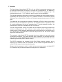
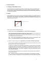
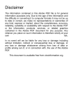
4 Autocal
AutoCal allows the user to ensure accuracy to the laboratory calibration by checking the span of
the transmitter and correcting for any deviation. It should be operated periodically, every 2 to 3
months, say, or can be used to verify operation of the SDT-Ex Transmitter if confirmation of an
unexpected result is required.
ACAL adjusts slope of curve.
Sensor Reading
100%
There are two methods of setting the autocal.
1) Saturate the transmitter (Only applicable to ºC and ºF SDT-Ex transmitters)
If the sensor element is exposed to a dewpoint level above the range of the transmitter, the
sensor will saturate and the transmitter output can be set as +20°C.
The easiest way to achieve this is to wrap ones hand around the sintered stainless steel
guard that protects the sensing element.
Note: - This is only recommended for transmitters used in non-toxic, non-poisonous, clean
gasses. Local Health and Safety Procedures should be followed at all times.
2) Expose to a known moisture level. (Applicable to all versions of SDT-Ex Transmitters)
If a known gas is available or the ambient dewpoint is known, then the autocal can be set to
the known value rather than the saturating value.
The SDT-Ex is supplied with an adjustable potentiometer to perform autocal, which allows
the calibration span of the transmitter to be adjusted. This potentiometer is located under the
weatherproof guard and can be accessed by undoing the large silver coloured screw on the
side of the transmitter body. The autocal is adjusted by turning the potentiometer with the
small screwdriver supplied.
The following steps describe the process of setting the autocal, describing the two different
methods where different.
Note: - The SDT-Ex must be connected to its normal indicator so that readings can be taken
or, where no indicator is employed, an accurate measurement of the mA output must be taken.
6
4.1 Pre-conditioning the transmitter
To perform the autocal, the transmitter needs to be removed from the process gas ready to be
saturated in the hand, or inserted into a known gas flow. At this stage, the display/indicator will
read the ambient dewpoint as measured by the SDT-Ex.
Saturating the Transmitter method (Only applicable to ºC and ºF SDT-Ex transmitters)
Saturate the transmitter by lightly covering the sintered aluminium area with a hand for
approximately 1 minute.
Expose to a known moisture level. (Applicable to all versions of SDT-Ex Transmitters)
Expose the transmitter to the known autocal moisture level and allow the transmitter to attain
equilibrium. (For technical questions and advice on the time taken to attain equilibrium
Contact your SDT-Ex supplier)
4.2 Adjust the Autocal
Once the transmitter has been pre-conditioned the Potentiometer can be adjusted. ONLY
ADJUST THE POTENTIOMETER IF THE SENSOR IS PROPERLY PRE-CONDITIONED.
FAILURE TO COMPLY WILL CORRUPT THE TRANSMITTERS CALIBRATION.
In the case of a transmitter saturated in the hand, the display should read +20°C (or 20mA if
reading current).
Note: - Always dry the output level down below 20ºC before wetting back up to exactly
20ºC.
If a known dewpoint is applied, then this value should be displayed.
4.3 Completing the autocal
Once the desired value is reached, the autocal process is completed and the screw driver
should be removed from the potentiometer and the weatherproof guard should be replaced
and fastened using the large silver coloured screw. If using the saturated transmitter method,
the transmitter can be put down on a work bench.
The SDT-Ex will now output the corrected dewpoint and can be reinserted into the process.
5 Faults/Errors
• If the sensor is short-circuited, the transmitter will produce a constant 20.75mA output.
• If the sensor is open-circuited, the transmitter will produce a constant 20.50mA output.
7
6 SDT Specification
Display:
Output Signal:
Operating Voltage:
Maximum Series Resistance:
Sensing element:
Autocal:
Factory calibration:
Accuracy:
Temperature compensation:
Resolution:
Repeatability:
Operating temperature:
Storage Temperature :
Operating Pressure:
Operating Humidity:
Sample Flow Rate:
Cable Terminations:
Compatible with the 4-20mA loop powered indicator.
4 to 20mA Linear
7V - 28V DC. Reverse polarity protected.
= {40 x (Supply Voltage – 7)} Ω
Ultra High Capacitance - Aluminium Oxide Type
Field calibration / Span check facility.
Supplied with Certificate of Calibration traceable to NPL / NIST
± 2°C dewpoint (NPL / NIST traceable for range -90°C to 20°C)
Temperature compensated for operating range.
5 µA
Better than ±0.3ºC dewpoint
-20°C to +60°C
-20°C to +70°C
From 1kPa (0.01 barA) to Maximum 35,000kPa (350 barA)
Maximum - 95% RH Non-condensing
Independent but ideally 2 to 5 litres per minute. Max: 25 litres/min.
IP66 (NEMA4X) rated, size C, DIN EN 175301 connector at the
transmitter and other end terminated with bootlace ferrules.
Cable:
Supplied with 2m standard cable. Nominal diameter 3.4mm,
92ohms/km.
Electromagnetic Compatibility (EMC):
Immunity: Complies with EN 61000-6-1:2001
Emissions: Complies with EN 61000-6-3:2001
Warm Up Time:
10 seconds
Fault Conditions:
Sensor Open Circuit
: Output drives to 20.50mA
Sensor Short Circuit
: Output drives to 20.75mA
Isolation:
Sensing Element connected to the 4-20mA loop but isolated from
body.
Transmitter Enclosure :
316 Stainless steel body with size C, DIN EN 175301 connector.
Sensor Protection:
316 Sintered stainless steel filter - 50 micron
Probe Material:
316 Stainless Steel
(Wetted Parts)
Weatherproof Classification:
IP66 / NEMA4X when Connector mated to Transmitter.
Mechanical Connection:
3/4” UNF (16tpi) with integral Viton “O” ring seal.
Mechanical Warranty:
24 months in case of faulty workmanship and defective parts.
Calibration Warranty:
12 months subject to usage.
Weight:
175grams (includes connector)
8
7
GUARANTEE
All Shaw products are guaranteed for two years from the date of purchase, some exclusions
are as follows:
Removing protective guard from any sensor, subjecting sensor to shock or black list gases e.g.
caustic and acidic gases like ammonia and chlorine, tampering with any internal electronics and
applying incorrect supply voltage to meters, subjecting to excessive flow rate, contaminants
and general mis-use.
If you suspect a fault which you feel needs to be attended to under guarantee please contact us
for assistance hopefully to help fault find and effect a remedy and if this is not successful to
give precise instructions for the return for inspection.
No equipment will be replaced or repaired without having been returned for inspection either to
ourselves or an authorised distributor.
8 Basic Definitions
WATER VAPOUR PRESSURE
Is the pressure exerted by the water vapour contained in any mixture of gases. The total
pressure exerted by the gas mixture is the sum of the pressures exerted by its components including the water vapour. Water vapour pressure varies in direct proportion to the total gas
pressure.
RELATIVE HUMIDITY
Is the ratio of the actual water vapour pressure to the saturation water vapour pressure at the
same temperature.
DEWPOINT TEMPERATURE
Is defined as the temperature to which the gas must be cooled in order that it should be
saturated with water vapour (i.e.100% relative humidity). For practical reasons it is referred to
water above 0 deg C and ice below 0 deg C.
PARTS PER MILLION BY VOLUME
PPM(V) or VPM is the ratio of the water vapour pressure to the total gas pressure.
PARTS PER MILLION BY WEIGHT
PPM(W) is the same as VPM, except that the figure is modified according to the ratio of the
molecular weight of water vapour to the molecular weight of the carrier gas mixture.
9
10
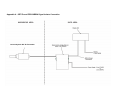
Appendix A – SDT-Ex and PR5104BB2A Signal Isolator Connection
Intrinsically Safe SDT-Ex Transmitter
1
Appendix B – PR5104BB2A to SDT-Ex Connections
SDT-Ex Transmitter Cable Connection (Channel 1)
SDT-Ex Transmitter Cable Connection (Channel 2 If Applicable)
2
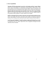
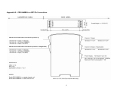
Appendix C – SDT-Ex with Connector, General Arrangement
34.0ø (1.34 dia.)
57mm (2.25)
Process thread
¾ x 16 UNF
54.5mm (2.15)
30mm (1.185) A/F
1
10 (0.4)
43 (1.7)
The Assembly is shown with 1/4 OD tube fittings.
The dimension across the tube fittings will vary
for all other size fittings.
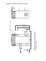
43 (1.7)
44 (1.73)
54 (2.125)
2 Mounting Holes 5.5ø (0.22 dia.)
34ø (1.34 dia)
54 (2.125)
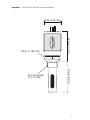
Appendix B – Transmitter Holder General Arrangement
68 (2.68)
58 (2.28)
15 (0.6)
2