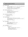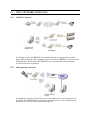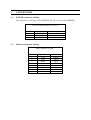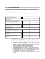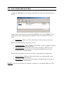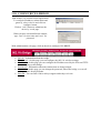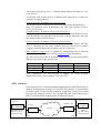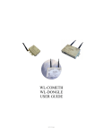
1
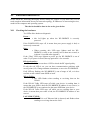
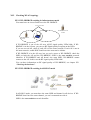
WL-BRIDGE
USER GUIDE
D
DTTU
USS004499
-iWL-BRIDGE USER GUIDE
COPYRIGHT (©) ACKSYS 2003
This document contains information protected by Copyright.
The present document may not be wholly or partially reproduced, transcribed, stored in any
computer or other system whatsoever, or translated into any language or computer language
whatsoever without prior written consent from ACKSYS, 3 & 5 rue du Stade, BP 4580, 78302
POISSY CEDEX.
REGISTERED TRADEMARKS ®
• ACKSYS is a registered trademark of ACKSYS.
• Windows is a registered trademark of MICROSOFT.
NOTICE
ACKSYS ® gives no guarantee as to the content of the present document and takes no
responsibility for the profitability or the suitability of the equipment for the requirements of
the user.
ACKSYS ® will in no case be held responsible for any errors that may be contained in this
document, nor for any damage, no matter how substantial, occasioned by the provision,
operation or use of the equipment.
ACKSYS ® reserves the right to revise this document periodically or change its contents
without notice.
3 & 5 rue du Stade
BP 4580
78302 POISSY CEDEX
FRANCE
Telephone:
Fax:
Web:
Hotline:
Sales:
+33 (0)1 39 11 62 81
+33 (0)1 39 11 47 96
www.acksys.fr
[email protected]
[email protected]
WL-BRIDGE USER’S MANUAL (D
DTTU
USS004499) Release A-00, october 22, 2003
- ii -
PAGE INTENTIONALLY LEFT BLANK
WL-COMETH USER’S MANUAL (D
DTTU
USS004499) Release A-00, october 22, 2003
- iii -
TABLE OF CONTENTS
I.
INTRODUCTION........................................................................................................... 5
I.1
I.2
PURPOSE OF THIS MANUAL ...................................................................................... 5
PRODUCT DESIGNATION ........................................................................................... 6
II. PACKAGE CHECKLIST .............................................................................................. 8
III.
PRODUCT SPECIFICATIONS ............................................................................... 10
III.1
III.2
III.3
III.4
III.5
III.6
III.7
III.8
III.9
IV.
WIFI NETWORK TOPOLOGY .............................................................................. 12
IV.1
IV.2
V.
AD-HOC NETWORK............................................................................................. 12
INFRASTRUCTURE NETWORK ................................................................................ 12
CONNECTORS............................................................................................................. 14
V.1
V.2
VI.
CHARACTERISTICS................................................................................................ 10
DC POWER (FOR DC VERSION) ............................................................................ 10
AC POWER (FOR AC VERSION)............................................................................. 10
WLAN INTERFACE............................................................................................... 10
LAN INTERFACE .................................................................................................. 10
LED INDICATORS .................................................................................................. 10
ENVIRONMENTAL LIMITATIONS ............................................................................ 11
PRODUCT INFORMATION LABEL ............................................................................ 11
MECHANICAL CHARACTERISTICS ......................................................................... 11
POWER CONNECTOR CABLING ............................................................................. 14
ETHERNET CONNECTOR CABLING .......................................................................... 14
GETTING STARTED................................................................................................ 15
VI.1
VI.2
VI.3
VI.4
VI.5
COLLECT NETWORK CHARACTERISTICS ................................................................ 15
CONNECT POWER ADAPTER .................................................................................. 16
CONNECT NETWORK CABLE.................................................................................. 16
FIND WL-BRIDGE DEVICE ON YOUR NETWORK ................................................. 16
ADMINISTRATION BY WLAN / LAN.................................................................... 16
VII. LOCATOR APPLICATION ..................................................................................... 17
VIII. CONFIGURE WL-BRIDGE ..................................................................................... 18
IX.
UPGRADE YOUR WL-BRIDGE............................................................................. 19
WL-BRIDGE USER’S MANUAL (D
DTTU
USS004499) Release A-00, october 22, 2003
- iv -
X.
XI.
SECURITY .................................................................................................................... 20
TROUBLESHOOTING............................................................................................. 21
XI.1
XI.2
XI.3
XI.4
CHECKING THE HARDWARE .................................................................................. 21
CHECKING WLAN TOPOLOGY ............................................................................. 22
CHECKING THE NETWORK TOPOLOGY ................................................................... 23
CHECKING THE CONFIGURATION .......................................................................... 24
XII. ADDRESSING IN NETWORK PROTOCOLS ...................................................... 25
XII.1
XII.2
XII.3
XII.4
XII.5
TCP/IP NETWORK LAYERS ................................................................................... 25
SSID .................................................................................................................... 25
ETHERNET ADDRESS ............................................................................................ 25
IP ADDRESS .......................................................................................................... 25
GATEWAYS........................................................................................................... 26
XIII. NOTES......................................................................................................................... 28
XIV. DEFECT REPORT FORM ....................................................................................... 30
WL-COMETH USER’S MANUAL (D
DTTU
USS004499) Release A-00, october 22, 2003
I.
INTRODUCTION
I.1
Purpose of this manual
This manual could be obsolete. Please download last documentation on our
web site (www.acksys.fr)
This manual provides instructions to easily install and configure the WLBRIDGE product on your network.
Chapter II “Package checklist” allows you to check if your package was
complete when delivered.
Chapter III “Product specifications” describes the fundamental possibilities
of the product.
Chapter IV “WIFI network topology” describes the Ad-Hoc and
Infrastructure installation of the WL-BRIDGE.
Chapter V “Connectors” describes the power connector and ethernet
connector of the WL-BRIDGE.
Chapter VI “Getting started” is a step-by-step description of a typical WLBRIDGE installation in a simple application context.
Chapter VII “locator application” describe the functionality of locator
application.
Chapter VIII “Configure WL-BRIDGE” describe the WL-BRIDGE
configuration web page.
Chapter IX “Upgrade your WL-BRIDGE” describe upgrade process.
Chapter X “Security” describe security in WL-BRIDGE.
Chapter XI “Troubleshooting” gives hints on what to do when the
installation fails.
Chapter XII “Addressing in Network protocols” gives some background in
networking, required to install the WL-BRIDGE.
It is expected that the reader of this manual has some background
knowledge of TCP/IP and how to setup and use TCP/IP on a Windowsbased PC. As well, anyone installing a WL-BRIDGE should know how
his/her network is organized.
I.2
Product designation
WL-BRIDGE is a 802.11b Wireless Network Bridge.
Wireless Bridge is used as a gateway between a wired network and a 11 Mbps
wireless network.
WL-BRIDGE is provided with tools of configuration and update. See section
“Upgrade your WL-BRIDGE” for more information.
PAGE INTENTIONALLY LEFT BLANK
PACKAGE CHECKLIST
II.
The WL-BRIDGE package contains the following components :
•
•
•
•
•
One WL-BRIDGE device
One main supply cable
ACKSYS PRODUCT RANGE CD-ROM
Two antennas
One network crossed cable with RJ45.
PAGE INTENTIONALLY LEFT BLANK
III.
PRODUCT SPECIFICATIONS
III.1 Characteristics
Metal housing including RJ45 ethernet interface 10BT, WIFI interface
(802.11b) at 11 Mbit/s.
External power supply 9 to 36 VDC for WL-BRIDGE-DC
Internal power supply 85 to 246 VAC for WL-BRIDGE
Power supply protection by current limitation
III.2 DC Power (for DC version)
External power 9 to 36 VDC
DC POWER via 3 pins screw terminal connector
Maximum current 280 mA at 9 VDC
Power consumption : 2.5W max
III.3 AC power (for AC version)
Main power 85 to 246 VAC
47-440 Hz 3W
III.4 WLAN interface
WIFI 802.11b interface, Ethernet speed 1,2,5.5,11 Mbps
300 m nominal range (open space) from access point, 60 m in other cases.
4 WEP key 64/128 bits.
IP Protocols: IPv4, ICMP, HTTP.
III.5 LAN interface
Ethernet 10 BASE T, RJ45 Ethernet connector
Ethernet II, IEEE 802.3
Ethernet speed 10 Mbps
IP Protocols: IP V4, HTTP, ICMP, DHCP.
III.6 Led indicators
Ten LED indicators :
Power
Diagnostic / general-purpose mode / reboot indicator
LAN interface Link, Rx/Tx activity
WLAN interface Rx/Tx activity
RF signal quality on WLAN interface
III.7 Environmental limitations
Operating temperature: 0°C to 65°C
Storage temperature: -40°C to +85°C
Humidity: 0-95% RH (without condensation)
III.8 Product information label
Located on the underside of the WL-BRIDGE, it contains the following
information:
• Product name
• Product serial number
III.9 Mechanical characteristics
Metal housing
Size: 17×15×4,2 cm (6.7×6×1.6 in) (antenna plugs not included, fastening
included)
Weigth : 0.700 Kg (1.54 lbs)
Two omni-directional antennas, 2dBi. You can replace them by an antenna
with more gain, through External antenna (RSMA) connector.
IV.
WIFI NETWORK TOPOLOGY
IV.1 AD-HOC network
In AD-HOC mode, WL-BRIDGE can establish directly a communication with an
other WIFI equipment. This equipment can be an other WL-BRIDGE or a device with
WIFI interface. In this mode, WL-BRIDGE can’t communicate with an Ethernet
10/100 BT interface equipment.
IV.2 Infrastructure network
In infrastructure mode, you must have an Access Point (AP) in your application. In
this mode, WL-BRIDGE can communicate with all devices on your wired network
and all devices on your WIFI network through AP.
PAGE INTENTIONALLY LEFT BLANK
V.
CONNECTORS
V.1
POWER connector cabling
This connector is valid only on WL-BRIDGE-DC (DC version of WL-BRIDGE)
Screw terminal connector (3 pins)
PIN
1
2
3
V.2
Signal name
EARTH
+VDC (9-36V)
GND
Description
Protective ground
Positive power supply
Ground power supply
Ethernet connector cabling
RJ45 connector (8 pins)
PIN
1
2
3
4
5
6
7
8
Signal name
TxD+
TxDRxD+
N.C.
N.C.
RxDN.C.
N.C.
Direction
Output
Output
Input
Not Connected
Not Connected
Input
Not Connected
Not Connected
VI.
GETTING STARTED
This chapter describes the required steps to get WL-BRIDGE device on-line and working.
VI.1 Collect network characteristics
You will need at hand the following information about your WLAN:
Will the WL-BRIDGE use DHCP :
If DHCP is used:
•
Does the network administrator (or the
DHCP server) require a specially crafted
Client ID (DHCP option 61)?
client identifier:
___________________
•
Does the network administrator (or the
DHCP server) require a Client Host Name
(DHCP option 12)?
hostname identifier:
___________________
If DHCP is not used:
•
IP address for the WL-BRIDGE (see
below):
•
Does your WLAN need use of a
netmask?
Netmask value :
___.___.___.___
•
Will the admin connection cross a
gateway?
Gateway address:
___.___.___.___
___.___.___.___
WL-BRIDGE IP address: You must assign an IP address to the WLBRIDGE. YOU CANNOT JUST PICK ONE AT RANDOM and wish it
will work! The chosen address must meet the following requirements :
•
•
•
•
•
•
Its network part must match the network part of other devices on the
same WLAN/LAN,
Its host part must be different from any other devices on the same
WLAN/ LAN (beware of printers, routers and gateways),
Its host part must not be a reserved value like 0 or 255.
WL-BRIDGE used the same IP address on WLAN and LAN interface.
WL-BRIDGE must have one SSID to indicate the network to which will
be connected the WiFi devices. The several devices and the Access
Point of the same WiFi network must have the same SSID.
You must choose a radio channel in addition to the SSID to define the
network.
NETMASKS: If no netmask applies, it can be deduced from the IP address
class:
Class A
netmask 255.0.0.0
Class B
netmask 255. 255.0.0
Class C
netmask 255. 255. 255.0
If in doubt, please ask to the local Network Administrator.
VI.2 Connect power adapter
Connect the power supply to the WL-BRIDGE.
Notice WL-BRIDGE has no ON/OFF switch. It turns on automatically
when power supply is connected.
VI.3 Connect network cable
The cable given with WL-BRIDGE is crossed. Use it to connect
WL-BRIDGE directly to Ethernet device (Computer for example).
If you want to plug WL-BRIDGE on Hub, Switch or router, used a straight
cable.
If WL-BRIDGE is connected successfully to the network, the LINK LED is
on. See section “Checking the hardware” for more information.
VI.4 Find WL-BRIDGE device on your network
The default IP address of WL-BRIDGE is 192.168.1.253 and subnet mask is
255.255.255.0.
To change IP address of your WL-BRIDGE, run locator.exe on acksys CDROM. See section “locator application” for used locator.exe
If your WL-BRIDGE is behind gateway, Locator can’t find your device. In
this case used computer on the same network, or put WL-BRIDGE in the
same network for initialization.
VI.5 Administration by WLAN / LAN
To change any parameter of WL-BRIDGE, run th administration web page.
Execute your web browser, and in address field type http://192.168.1.253,
(192.168.1.253 is default IP address of WL-BRIDGE, if you have already
change WL-BRIDGE’s IP address type your IP address).
To enter in administration module you must type a user name and password.
The default user name is “root”, and the default password is “root”.
VII. LOCATOR APPLICATION
Locator application it used to configure and to upgrade WL-BRIDGE.
Connect WL-BRIDGE to your computer with Ethernet cable, and execute locator.exe
on CD.
Locator scans your network to locate all WL-BRIDGE, If your WL-BRIDGE is not
ready (turn on, and connected on your computer), click on scan button when it is
ready.
Scan Button : When you click on this button, locator searchs you devices.
Before using others buttons, first select a device.
Configure button : When you click on this button, you can configure IP address
of WL-BRIDGE or activate DHCP.
Auto IP button : If this button is valid, when you click on, DHCP server is
automaticly enable on your device. If you haven’t DHCP server on your
network, don’ t used this button.
For the following buttons your device must have a good network configuration.
Upgrade button : When you click on this button, you can donwload a new
firmware in selectionned device.
Web Button : When you click on this button, the administration web page is
running with the selected device.
NOTE : If you use firewall on your computer, configure it, to not block UDP port 17784.
VIII. CONFIGURE WL-BRIDGE
Run locator, (see section locator application)
To configure IP address, subnet mask and
gateway, select a device and click on
configure button.
Click on “web” button to administer the
device by a web page.
When you have an identification window,
type “root” for user name and “root” for
password.
With administration web page, click on the tab to configure WL-BRIGE.
Info tab : Information about the bridge.
Wireless tab : On this page you can configure the 802.11b wireless settings.
IP addr tab : On this page you can configure the IP address used by the Web and TFTP
servers running on this bridge.
Stations tab : Information about the stations that are being bridged.
Admin tab : On this page you can change the password, reboot the bridge, or reset all
settings to their factory defaults.
Help tab : You can find a link to acksys support and acksys web site.
IX.
UPGRADE YOUR WL-BRIDGE
To upgrade WL-BRIDGE’s firmware. The latest firmware is downloadable on our
web site (www.acksys.fr).
Sequence of update:
1.
2.
3.
4.
5.
6.
7.
Run locator.
Select your device in list.
Click on upgrade button.
Choose your file (you can type file’s path or click on choose button).
Click on upgrade button.
If upgrade is well-down WL-BRIDGE restarts.
If you have an error, correct the problem and try again.
NOTE : WL-BRIDGE‘s Network configuration must be correct to launch the upgrade. to test
the network configuration, see section Checking the network topology.
X.
SECURITY
Several levels of security are parametrables. In its default setting, the WL-BRIDGE is
does not activate any function of advanced security. To harden the confidentiality of
the network exchanges, you have the following functions:
Wep key : when wep key is enable, data is crypted with the used key. If you
want to use wep key, all WIFI devices (Access point, bridge, computer …)
must use the same wep key. To enable wep key, you have to use security tab in
administration web page.
Deny unencrypted data : If you use wep key, you can enable this option. When
this option is enable, wifi not crypted packets are ignored. If this option is not
enable, wifi not crypted packets are sent to Ethernet interface. To activate this
option used security tab in administration web page.
Block upgrade : When your installation is completed and it’s running, you can
block upgrade. When this option is enabled, it is impossible to upgrade
WL-BRIDGE. If you want to make an upgrade you must disable this option.
You can enable this option with admin tab on administration web page.
Change login and password : Don’t use default login (“root” “root”) because
all Acksys devices had this login by default, and it easy to find it. You can
change login with admin tab in administration web page.
XI.
TROUBLESHOOTING
Please check the following thoroughly before calling for support. If you must call, we will
need complete information about your network topology, IP addresses of intervening devices,
model of the computer and operating system.
The checks should be done in the order given below.
XI.1 Checking the hardware
Ten LEDs allow hardware diagnostic.
Power :
• this led lights up when the WL-BRIDGE is correctly
powered.
If the POWER LED stays off, it means that your power supply is bad, or
incorrectly connected.
Diag :
• When resetting, this LED stays lighten until the WLBRIDGE is ready to use (usually in less than one second, or
in about 10 seconds after upgrade)
If the “Diag” LED stays lighten at power up, the WL-BRIDGE is out of
order. Try to power it down, then up again after a few seconds.
RF signal quality :
• You can use these 6 LED to check the RF signal quality.
If only the red LED is on, you can have communication problems with
access point (AP). Change antennas orientation, or move the WL-BRIDGE.
If all LED are flashing, the WL-BRIDGE is out of range of AP, or it does
not find an AP with the same SSID as itself.
WLan Tx/Rx :
• this LED flashes when sending or receiving data on the
WLAN.
If the WLAN Tx/Rx LED stays off while your device is sending data, it
means that your SSID is bad, the WL-BRIDGE IP address is not correct, or
the WL-BRIDGE is not connected to the same SSID than your device.
If the WLAN Tx/Rx LED stays off while you are sending data to your
device, it means that your cable is bad, the WL-BRIDGE IP address is not
correct.
LAN LINK, TX/RX :
• This LED is on if Ethernet link is detected, and flashes when
sending or receiving data on the LAN.
XI.2 Checking WLAN topology
XI.2.1 WL-BRIDGE working in infrastructure mode
You must have an Access Point to use the WL-BRIDGE.
Access point area
WL-BRIDGE out of
AP area
WL-BRIDGE in
AP area
Access point (AP)
If WL-BRIDGE is out of the AP area, all RF signal quality LEDs blink. If WLBRIDGE is in the AP area, you can see RF Signal quality reception on the LEDs.
If you use several AP, check if each AP is in the same network. If each AP is not in
the same network, enable DHCP and lease time must not be infinite.
If WL-BRIDGE is in the AP area, but you can’t access to WL-BRIDGE, check the
SSID on both the AP and the WL-BRIDGE. SSID is the case sensitive network
identifier. If WL-BRIDGE and AP haven’t the same SSID, WL-BRIDGE cannot
connect to the AP. In this case the RF signal quality LEDs blink.
You can have information on RF signal quality of WL-BRIDGE, see chapter XI.1
“Checking the hardware”.
XI.2.2 WL-BRIDGE working in AD-HOC mode
In AD-HOC mode, you must have the same SSID and channel in all devices. If WLBRIDGE don’t have the same channel, you can’t communicate with it.
SSID is the case sensitive network identifier.
XI.3 Checking the network topology
In the following examples the WL-BRIDGE IP address is 192.168.1.253 ; the computer used
for the tests has IP address 192.168.1.244.
• First you must ensure that the WL-BRIDGE has an unique IP address on the local
network. Turn off the WL-BRIDGE (unplug supply connector), then try to PING the
WL-BRIDGE address from a computer connected to the local network. This should
result in an error or timeout :
C:\>arp –d 192.168.1.253
C:\>ping 192.168.1.253
Pinging 192.168.1.244 with 32 bytes of data :
Request timeout.
Request timeout.
Request timeout.
Request timeout.
The « Request timeout » error messages are normal and expected in this
case. If this is not the case, another host has the same IP address. Correct the
problem.
If the answer is some message like « no route to host », the computer you
are using for the test has no access to the WL-BRIDGE’s LAN, or the
network part of the IP address of the WL-BRIDGE is incorrect.
• Now turn on the WL-BRIDGE (plug supply connector) and try to PING it :
C:\>arp –d 192.168.1.253
C:\>ping 192.168.1.253
Pinging 192.168.1.244 with 32 bytes of data :
Answer from 192.168.1.253 : bytes=32 time<10ms
Answer from 192.168.1.253 : bytes=32 time<10ms
Answer from 192.168.1.253 : bytes=32 time<10ms
Answer from 192.168.1.253 : bytes=32 time<10ms
TTL=64
TTL=64
TTL=64
TTL=64
If there is no answer, the IP address of the WL-BRIDGE is not this one.
Correct the problem with the administration system. Be sure to save the
changed configuration.
• Then, if you need to cross a gateway, PING the WL-BRIDGE from a computer
installed on the other side of the gateway.
DO NOT just move the above-mentioned computer from one LAN to the
other ! You must set a new, appropriate IP address and SSID in the
computer when you move it from one LAN to another.
If there is no answer, the gateway IP address or the netmask is improperly
set in the WL-BRIDGE or in your computer. Correct the problem with the
administration system. Be sure to save the changed configuration and reset
the WL-BRIDGE.
Also the gateway itself may be improperly set. Check with your network
administrator.
Did you set the gateway address (if any) in the WL-BRIDGE ? Else the
WL-BRIDGE can receive the PING but does not know where to send the
answer.
XI.4 Checking the configuration
When you can PING the WL-BRIDGE, you should be able to use remote
administration. Try to connect to the administration system :
C:\> explorer http://192.168.1.253
You should runing your web browser and in field address pick
http://192.168.1.253 (replace 192.168.1.253 by your IP address).
XII. ADDRESSING IN NETWORK PROTOCOLS
XII.1 TCP/IP network layers
TCP/IP is the name of the protocols used by Internet and many Intranets.
In a device participating in a TCP/IP network, there are four software layers:
the application layer, the transport layer (TCP or UDP), the network
layer (IP), the LAN layer (Ethernet, Wifi, point-to-point modems, etc.)
The LAN layer address allows a device to send data to another device
connected to the same LAN. But there is not enough information in a LAN
address to send to a device connected on another LAN through a router.
The Network (IP) address solves this problem by defining addresses which
can be subject to routing. When the source and destination devices are not
on the same LAN, the source device can send data to an intermediate
gateway (also called router). The gateway has routing tables which allows it
to forward data to the destination device, maybe through other gateways.
The a transport layer address, called a “port”, is used inside a destination
device to deliver data to the correct application process.
XII.2 SSID
The SSID (Service Set IDentifier), which is set on every wireless stations
and AP, defines the logical network for the group of wireless network
devices that share that particular SSID. You can use any keyboard
characters to specify the SSID in WL-bridge. SSID is case sensitive.
XII.3 Ethernet Address
The Ethernet address is also referred to as the hardware address or MAC
address. This address is assigned at the factory and should not be changed.
An Ethernet LAN can be made of hubs, switches, bridges, access points.
These must not be confused with IP gateways (see below).
XII.4 IP address
The IP address is a 4 bytes number unique to each device on the network,
which hosts can use to communicate.
IP addresses can be private or public. Public ones are reserved to devices
that require to send data over a public network, such as internet. They are
usually purchased or leased from a local ISP.
The IP address is usually represented in the “decimal dotted notation” which
consists of the decimal value of each of the four bytes, separated by dots.
The IP address is divided into two parts : network and host. To support
different needs, three network classes have been defined. In the following,
‘x’ stands for the host part of the IP address.
A host part with all bits set to 1 is the broadcast address, meaning for « for
every device ».
A host part with all bits fixed to 0 addresses the network as a whole (for
example, in routing entries).
Class A network : IP address 1.x.x.x to 127.x.x.x
The first byte defines the network and the last three bytes define the host.
Only 127 different class A networks exist, and each consist of up to
16.777.216 devices
Class B network : IP address 128.0.x.x to 191.255.x.x
The first two bytes define the network and the last two bytes define the host.
Class B networks are typically used for large company networks, and each
can consist of up to 65,534 devices.
Class C network : IP address 192.0.0.x to 223.255.255.x
The first three bytes define the network and the last byte defines the host.
Class C networks are the most common and are often used in smaller
company, and each network can consist of up to 254 devices.
More complex classes can be defined by manipulating the IP netmask
associated with the IP address. See the www.ietf.org documentation.
The bits set to one in the IP netmask define the bits of the associated IP
address to be taken as the network part.
Network class
A
B
C
Network bits
8
16
24
Host bits
24
16
8
Netmask
255.0.0.0
255.255.0.0
255.255.255.0
Each wl8bridgehas one user-assigned IP address. Its factory-assigned
default value is the Class C address “192.168.1.253”.
XII.5 Gateways
Each network device communicating through gateways MUST know the IP
address of the gateway nearest to it. It will use this gateway to forward data
to farther LANs. If a device does not know its gateway, it may receive data
but may not return an answer. For example this can forbid answering a
PING even if the PING request makes its way to the device.
CONNECTING THROUGH GATEWAYS - EXAMPLE
192.168.1.12
10.1.2.30
Device#1
(WL-BRIDGE)
Must know about
address 10.1.2.1 to
send to Device#2
192.168.1.254
10.1.2.1
Gateway#1
LAN
Internet
Gateway#2
LAN
Device#2
(computer)
Must know about
address
192.168.1.254 to
send to Device#1
PAGE INTENTIONALLY LEFT BLANK
XIII. NOTES
NOTES
XIV. DEFECT REPORT FORM
Name
Company
Telephone
Fax
E-mail
WL-BRIDGE
Operating system
driver version
Type of computer
Description of the problem
......................................................................................................................................................
......................................................................................................................................................
......................................................................................................................................................
......................................................................................................................................................
......................................................................................................................................................
......................................................................................................................................................
......................................................................................................................................................
......................................................................................................................................................
......................................................................................................................................................
3 & 5 rue du Stade
BP 4580
78302 POISSY CEDEX
FRANCE
Telephone:
Fax:
Web:
Hotline:
Sales:
+33 (0)1 39 11 62 81
+33 (0)1 39 11 47 96
www.acksys.fr
[email protected]
[email protected]