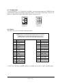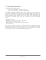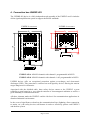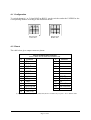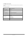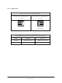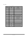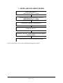
1
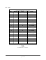
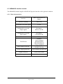
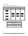
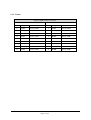
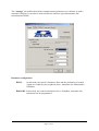
UNXPCI HARDWARE & SOFTWARE USER’S MANUAL 4/8 Ports Industrial Serial Board for PCI bus with external connectivity box RS232 RS422 Isolated RS232 Isolated RS422/RS485 0-20 mA current loop TTL COMMUNICATIONS & SY STEMS ACKSYS Communications & Systems www.acksys.fr [email protected] [email protected] June 2007 (Release A.7) D DTTU USS002233 UNXPCI HARDWARE & SOFTWARE USER’S MANUAL COPYRIGHT ACKSYS 2002-2006 This document contains information that is protected by copyright. No part of this publication may be reproduced, transcribed, stored on any computer system or other system, translated into any language or into any computer language without prior written permission from ACKSYS, Z.A. Val joyeux – 10 rue des entrepreneurs 78450 Villepreux – France REGISTERED TRADEMARKS • • ACKSYS is a registered trademark of ACKSYS. Windows NT, Windows 95, Windows 98, Windows Me, Windows 2000, Windows XP and Windows Vista are registered trademarks of MICROSOFT. NOTICE ACKSYS provides this documentation “as is” without warranty of any kind. In no event shall ACKSYS be help responsible for the profitability and conformity of the hardware compared to the user’s requirements. ACKSYS shall not be held responsible for any errors that might be contained in this document, nor for any damages of any amount that the supply, operation or use of this equipment may entail. ACKSYS may revise this document from time to time, or change its contents, without notice. UNXPCI HARDWARE & SOFTWARE USER’S MANUAL ((D DTTU USS002233))– REL 7.JUNE 2007 Page 2 of 2 TABLE OF CONTENTS 1. 2. INTRODUCTION .......................................................................................................................................... 4 UNXPCI Board ............................................................................................................................................... 5 2.1 Synoptic .................................................................................................................................................. 6 2.2 Pinout of the output connector ................................................................................................................ 7 3. Connection box UNXBP-232 ......................................................................................................................... 9 3.1 Configuration ........................................................................................................................................ 10 3.2 Pinout .................................................................................................................................................... 10 3.3 Cable wiring recommendations............................................................................................................. 11 4. Connection box UNXBP-422 ....................................................................................................................... 12 4.1 Configuration ........................................................................................................................................ 13 4.2 Pinout .................................................................................................................................................... 13 4.3 Cable wiring recommendations............................................................................................................. 14 5. Connection box UNXBP-232-422 ................................................................................................................ 14 6. Connection box UNXBPMR......................................................................................................................... 15 6.1 MR232ISO interface module ................................................................................................................ 16 6.1.1 Main characteristics....................................................................................................................... 16 6.1.2 Configuration ................................................................................................................................ 17 6.1.3 Pinout ............................................................................................................................................ 18 6.2 MR400ISO interface module ................................................................................................................ 19 6.2.1 Main characteristics....................................................................................................................... 19 6.2.2 Configuration ................................................................................................................................ 20 6.2.3 Pinout ............................................................................................................................................ 21 6.3 MRBdc interface module ...................................................................................................................... 22 6.3.1 Main characteristics....................................................................................................................... 22 6.3.2 Configuration ................................................................................................................................ 23 6.3.3 Pinout ............................................................................................................................................ 24 7. INSTALLING THE UNXPCI BOARD ....................................................................................................... 25 8. INSTALLING THE ACKSYS DRIVER FOR WINDOWS ........................................................................ 26 8.1 Windows 9x, millennium device driver installation.............................................................................. 26 8.2 Windows NT device driver installation................................................................................................. 28 8.3 Windows 2000 / XP /Vista device driver installation ........................................................................... 30 8.3.1 Properties of all the communications ports ................................................................................... 30 9. INSTALLING THE ACKSYS DRIVER FOR LINUX KERNEL 2.2 ......................................................... 35 9.1 Using RS485 mode under Linux ........................................................................................................... 36 10. TROUBLESHOOTING GUIDE................................................................................................................... 37 11. Dimensions & consumptions ........................................................................................................................ 38 UNXPCI HARDWARE & SOFTWARE USER’S MANUAL ((D DTTU USS002233))– REL A.7 JUNE 2007 Page 3 of 3 1. INTRODUCTION INDUSTRIAL SERIAL COMMUNICATION BOARD, 4 OR 8 CHANNELS, WITH PCI PLUG & PLAY FEATURES UNXPCI card offers a reliable and very high performance solution for communication applications in industrial environment which need: - High-speed serial links, - Versatile interface (RS232, RS422, RS485, TTL…) The UNXPCI complies with the PCI Specification 2.1 or greater, which makes it easy to install (no jumper or switch for IRQ and I/O base address). All the board resources are automatically assigned by the PCI BIOS during the power-up of the P.C. The board is shipped with Windows drivers (95, 98, Me, NT 3.51/4.0, 2000, XP, Vista(32 bits)) and Linux drivers. Others drivers are supported by ACKSYS and can be shipped on request. Several UNXPCI cards can cohabit within a same machine to carry out 8, 16, 24 or 32 ports configurations. UNXPCI HARDWARE & SOFTWARE USER’S MANUAL ((D DTTU USS002233))– REL 7.JUNE 2007 Page 4 of 4 2. UNXPCI Board - 4 or 8 asynchronous serial communication ports, with D-SUB connectors on an external connection box. - Advanced communication functions : Automatic RS485 turn-around Flow control (hard/soft) handled by hardware Enhanced baud rate generator for non-standard speeds 128 bytes deep FIFO per transmitter and receiver RS422 baud rate up to 1.8 Mbps with standard 29.4912 MHz oscillator and up to 3.75 Mbps with optional 60 MHz oscillator. - Slave PCI 5V signaling interface 2.1 or greater - Polling Register (image of the eight interruption lines of each UART) - Programmable electrical interface: this mechanism will be used to configure the future connection boxes (electrical interface flavor, test mode...). - 4 input signals allow the identification of the connection box (BPID0 to BPID3) - 16 output signals allow the configuration of the connection box (CFG00 to CFG15). - 2 independent base addresses specified in PCI registers BAR0 & BAR1. BAR0: Base address for UNXPCI configuration registers (7 bytes) BAR1: Base Address for UNXPCI serial ports 1 to 8: 8x8 bytes = 64 (40H) Port addresses are consecutive The details of each register can be supplied upon request from customers who want to develop a device driver. UNXPCI HARDWARE & SOFTWARE USER’S MANUAL ((D DTTU USS002233))– REL A.7 JUNE 2007 Page 5 of 5 2.1 Synoptic J1: PCI connector (5V signaling only) J2: 100 pins connector to connect external box like UNXBP J3: Power connector OSC: 29.4912 MHz oscillator1 for UARTs U1: PCI interface and logic decoding U3/U4: Quad enhanced UARTs 16C550 compatible 1 Others oscillator values are available (60 MHz for very high speed serial link, 1,8432 MHz for full compatibility with standard communication ports…) UNXPCI HARDWARE & SOFTWARE USER’S MANUAL ((D DTTU USS002233))– REL 7.JUNE 2007 Page 6 of 6 2.2 Pinout of the output connector Solder side Rear view The external metallic frame is connected to the protected earth of the board. Each signal of the connector is TTL level compatible. Pin N° Direction Description Pin N° Direction Descri ption 1 I /DCD Channel 1 26 I /RI Channel 3 2 I /RI Channel 1 27 I /DCD Channel 3 3 I /DSR Channel 1 28 O CFG02 4 I /CTS Channel 1 29 I /DSR Channel 3 5 O TXD Channel 1 30 I GND 6 O /DTR Channel 1 31 I RXD Channel 4 7 O /RTS Channel 1 32 O +12V 8 I GND 33 O TXD Channel 4 9 I RXD Channel 1 34 O CFG03 10 O CFG00 35 O /RTS4 11 I RXD Channel 2 36 O -12V 12 O TXD Channel 2 37 O /DTR Channel 4 13 O /RTS Channel 2 38 I /CTS Channel 4 14 I /CTS Channel 2 39 I /DSR Channel 4 15 I /DCD Channel 2 40 I /DCD Channel 4 16 I /RI Channel 2 41 O +5V 17 I /DSR Channel 2 42 O +5V 18 O CFG01 43 I /RI Channel 4 19 O /DTR Channel 2 44 I BPID0 20 I GND 45 I BPID1 21 I RXD Channel 3 46 O CFG04 22 O TXD Channel 3 47 O CFG05 23 O /RTS Channel 3 48 O CFG06 24 O /DTR Channel 3 49 O CFG07 25 I /CTS Channel 3 50 I GND UNXPCI HARDWARE & SOFTWARE USER’S MANUAL ((D DTTU USS002233))– REL A.7 JUNE 2007 Page 7 of 7 Pin N° Direction Description Pin N° Direction Descri ption 51 I /DCD Channel 5 76 I /RI Channel 7 52 I /RI5 77 I /DCD Channel 7 53 I /DSR Channel 5 78 O CFG10 54 I /CTS Channel 5 79 I /DSR Channel 7 55 O TXD Channel 5 80 I GND 56 O /DTR Channel 5 81 I RXD Channel 8 57 O /RTS Channel 5 82 O +12V 58 I GND 83 O TXD Channel 8 59 I RXD Channel 5 84 O CFG11 60 O CFG08 85 O /RTS Channel 8 61 I RXD Channel 6 86 O -12V 62 O TXD Channel 6 87 O /DTR Channel 8 63 O /RTS Channel 6 88 I /CTS Channel 8 64 I /CTS Channel 6 89 I /DSR Channel 8 65 I /DCD Channel 6 90 I /DCD Channel 8 66 I /RI Channel 6 91 O +5V 67 I /DSR Channel 6 92 O +5V 68 O CFG09 93 I /RI Channel 8 69 O /DTR Channel 6 94 I BPID2 70 I GND 95 I BPID3 71 I RXD Channel 7 96 O CFG12 72 O TXD Channel 7 97 O CFG13 73 O /RTS Channel 7 98 O CFG14 74 O /DSR Channel 7 99 O CFG15 75 I /CTS Channel 7 100 I GND BPIDxx & CFGxx signals are reserved signals. UNXPCI HARDWARE & SOFTWARE USER’S MANUAL ((D DTTU USS002233))– REL 7.JUNE 2007 Page 8 of 8 3. Connection box UNXBP-232 The UNXBP-232 device is a fully independent sub-assembly of the UNXPCI card. It includes all the signal amplification system to support the RS232 standards. UNXBP-232 8 CHANNELS UNXBP-232 4 CHANNELS UNXPCI-232-4M: 4 RS232 (male connectors) channels with channel 1 switchable to RS422 UNXPCI-232-4F: 4 RS232 (female connectors) channels with channel 1 switchable to RS422 UNXPCI-232-8M: 8 RS232 channels (male connectors) with channels 1 & 5 switchable to RS422 UNXBP-232 devices offer an exceptional protection against overvoltages and electrostatic discharges (ESD). These protections are enforced on each signal by devices filtering the tension surges dangerous for electronics. Associated with the shielded cable, these safety devices ensure to the UNXPCI a great reliability a great longevity, a very reduced emission of electromagnetic radiation as well as a great immunity to external interference. All these elements make the UNXPCI card the ideal tool for communication applications in disturbed industrial environment. In the event of significant overload on the communication lines (lightning, direct connection to mains, etc.), the safety devices self-destruct in order to effectively protect card UNXPCI and the host system. UNXPCI HARDWARE & SOFTWARE USER’S MANUAL ((D DTTU USS002233))– REL A.7 JUNE 2007 Page 9 of 9 3.1 Configuration To switch channels 1 or 5 from RS232 to RS422, set the switches under the UNXBP for the corresponding channel according to the picture below. The RS422 termination resistor (121 Ohms) is automatically connected in RS422 mode on each receiver. RS232 mode Hidden dots RS422 mode Visible dots 3.2 Pinout The table below gives the output connector pinout. 25 pins D-SUB male or female connector UNXBP-232-4 exists with male or female output connectors. UNXBP-232-8 only exists with male output connectors. Notice that ports 1 and 5 can be switched in RS422 mode. n° Function n° Function PG 14 Not connected 2 TXD 15 Not connected 3 RXD 16 Not connected 4 RTS 17 Not connected 5 CTS 18 Not connected 6 DSR 19 Not connected 7 GND 0V 20 DTR 8 CD 21 RxB (–RX) (1) 9 +12VDC 22 RI 10 –12VDC 23 RxA (+RX) (1) 11 Not connected 24 Not connected 12 TxB (–TX) (1) 25 Not connected TxA (+TX) (1) 13 (1) The TxA, TxB, RxA and RxB signals are available only on ports 1 and 5 in RS422 mode UNXPCI HARDWARE & SOFTWARE USER’S MANUAL ((D DTTU USS002233))– REL 7.JUNE 2007 Page 10 of 10 3.3 Cable wiring recommendations The UNXBP is a RS232 DTE device, so to connect it to a DTE device, use a null-modem cable to connect it to a DCE device, use a straight through cable It is highly recommended to check attribution of pins 9 and 10 on the connector devices connected to the UNXBP; indeed, some modems use these pins to supply their electronics. In this case, we advise you not to connect these pins or to check that the consumption of the modem is compatible with the available current (750 mA MAX). A LED, when lit, shows that the UNXBP is correctly fed by the system. This indicator can stay off for the following reasons: - Bad cable connection - Breakdown on +12V and –12V voltages of the system - Short-circuit on a 25 D-SUB connector - Overload of the power voltages on the 25 D-SUB connector - Failure of the LED In the event of accidental short-circuit on D-SUB connectors it is recommended to power down the system and to detect the cause of the short-circuit. Be warned that the restartable thermal fuses protection will not allow to turn back on the power supply in the connection box, until the power supply has been turned off for at least 20 seconds. UNXPCI HARDWARE & SOFTWARE USER’S MANUAL ((D DTTU USS002233))– REL A.7 JUNE 2007 Page 11 of 11 4. Connection box UNXBP-422 The UNXBP-422 device is a fully independent sub-assembly of the UNXPCI card. It includes all the signal amplification system to support the RS422 standards. UNXBP 8 CHANNELS UNXBP 4 CHANNELS UNXPCI-422-4: 4 RS422 channels with channel 1 programmable in RS232 UNXPCI-422-8: 8 RS422 channels with channels 1 & 5 programmable in RS232 UNXBP devices offer an exceptional protection against overvoltages and electrostatic discharges (ESD). This protection is enforced on each signal by devices filtering the tension surges dangerous for electronics. Associated with the shielded cable, these safety devices ensure to the UNXPCI a great reliability a great longevity, a very reduced emission of electromagnetic radiation as well as a great immunity to external interference. All these elements make the UNXPCI card the ideal tool for communication applications in disturbed industrial environment. In the event of significant overload on the communication lines (lightning, direct connection to mains, etc.), the safety devices self-destruct in order to effectively protect card UNXPCI and the host system. UNXPCI HARDWARE & SOFTWARE USER’S MANUAL ((D DTTU USS002233))– REL 7.JUNE 2007 Page 12 of 12 4.1 Configuration To switch channels 1 or 5 from RS422 to RS232, set the switches under the UNXBP for the corresponding channel according to the illustration below. RS422 mode Visible dots RS232 mode Hidden dots 4.2 Pinout The table below gives output connector pinout. n° 25 pins D-SUB female connector Ports 1 and 5 can be switched in RS232 mode. Function n° Function 14 Not connected 2 TXD (1) 15 Not connected 3 RXD (1) 16 Not connected 4 RTS (1) 17 Not connected 5 CTS (1) 18 Not connected 6 DSR (1) 19 Not connected 7 GND 0V 20 DTR (1) 8 CD (1) 21 RxB (–Rx) 9 +5VDC 22 RI (1) 10 –12VDC 23 RxA (+Rx) 24 Not connected 25 Not connected PG 11 Not connected 12 TxB (–Tx) 13 TxA (+Tx) (1) Signals TXD, RXD, RTS, CTS, DSR, DTR, RI are available only on ports 1 & 5 in RS232 mode. UNXPCI HARDWARE & SOFTWARE USER’S MANUAL ((D DTTU USS002233))– REL A.7 JUNE 2007 Page 13 of 13 4.3 Cable wiring recommendations It is highly recommended to check attribution of pins 9 and 10 on the connector devices connected to the UNXBP; indeed, some modems use these pins to supply their electronics. In this case, we advise you not to connect these pins or to check that the consumption of the modem is compatible with the available current (750 mA MAX). A LED shows, when lit, that the UNXBP is correctly fed by the system. This indicator can stay off for the following reasons: - Bad cable connection - Breakdown on +12V and –12V voltages of the system - Short-circuit on a 25 D-SUB connector - Overload of the power voltages on the 25 D-SUB connector - Failure of the LED In the event of accidental short-circuit on D-SUB connectors it is recommended to power down the system and to detect the cause of the short-circuit. Be warned that the restartable thermal fuses protection will not allow to turn back on the power supply in the connection box, until the power supply has been turned off for at least 20 seconds. 5. Connection box UNXBP-232-422 The UNXBP-232-422 device only exists with 8 channels. The first four channels are compatible with the UNXBP-232-4M device and the last four are compatible with the UNXBP-422-4 device. UNXPCI HARDWARE & SOFTWARE USER’S MANUAL ((D DTTU USS002233))– REL 7.JUNE 2007 Page 14 of 14 6. Connection box UNXBPMR 225.00 mm 116.00 mm 255.00 mm The UNXBPMR device is a fully independent sub-assembly of the UNXPCI card. It includes all the amplification system to support RS232, RS422, RS485 and 0-20 mA current loop standards. It is composed of a 8-positions pack with 4 or 8 interface modules. You can choose a different interface module for each line. The following interface modules are available: MR232ISO interface module: RS232, isolation up to 2KV MR400ISO interface module: RS422/RS485, isolation up to 2KV MRBdc interface module: 0-20mA current loop, isolation up to 2KV UNXPCI HARDWARE & SOFTWARE USER’S MANUAL ((D DTTU USS002233))– REL A.7 JUNE 2007 Page 15 of 15 6.1 MR232ISO interface module The MR232ISO module supplies a RS232 physical interface with a galvanic isolation. 6.1.1 Main characteristics Interface RS232 DTE Galvanic isolation 2000 Veff Permanently converted signals Tx, Rx Configurable converted output signals By switches: one of RTS or DTR or TXCLK Configurable converted input signals Max. bit rate Visualization High voltage protection By switches: one of CTS or DCD or RI or DSR or RXCLK or TXCLK-I 230 Kbps POWER TX (TX Signal) RX (RX Signal) CtrlOUT (Output signal) CtrlIN (Input signal) ESD 15 kV, EMI/RFI filtering Power supply protection Fast restartable thermal fuse Output connector 25 pins D-sub female Consumption 145 mA max UNXPCI HARDWARE & SOFTWARE USER’S MANUAL ((D DTTU USS002233))– REL 7.JUNE 2007 Page 16 of 16 6.1.2 Configuration Two configuration switches (SW1 and SW2) located on-module are used. To modify the factory settings (RTS/CTS), first unscrew and remove the module. CONFIGURABLE CONVERTED OUTPUT SIGNAL SW1 SW2 on on RTS (factory setting) 1 2 3 4 5 6 7 8 on 1 2 3 4 5 6 7 8 2 3 4 5 6 7 8 on DTR 1 2 3 CONFIGURABLE CONVERTED INPUT SIGNAL 4 5 6 7 8 1 SW1 SW2 on on CTS (factory setting) 1 2 3 4 5 6 7 8 on 1 2 3 4 5 6 7 8 2 3 4 5 6 7 8 2 3 4 5 6 7 8 2 3 4 5 6 7 8 on DCD 1 2 3 4 5 6 7 8 on 1 on RI 1 2 3 4 5 6 7 8 on 1 on DSR 1 2 3 4 5 6 7 8 1 UNXPCI HARDWARE & SOFTWARE USER’S MANUAL ((D DTTU USS002233))– REL A.7 JUNE 2007 Page 17 of 17 6.1.3 Pinout 25 pins D-SUB female connector Pin N° Direction Name Function 1 I PGND Earth 2 O TXD Transmitted data 3 I RXD Received data 4(*) O RTS Request to send 5(*) I CTS Clear to send 6(*) I DSR Data Set Ready 7 I GNDI Isolated ground 8(*) I DCD DCD 9 NC Not connected 10 NC Not connected 11 NC Not connected 12 NC Not connected 13 NC Not connected 14 NC Not connected 15 NC Not connected 16 NC Not connected 17 NC Not connected 18 NC Not connected 19 NC Not connected DTR Data Terminal Ready NC Not connected RI Ring Indicator 23 NC Not connected 24 NC Not connected GNDI Isolated ground 20(*) O 21 22(*) 25 I I I: Input. O: Output. (*) Configurable by switches. UNXPCI HARDWARE & SOFTWARE USER’S MANUAL ((D DTTU USS002233))– REL 7.JUNE 2007 Page 18 of 18 6.2 MR400ISO interface module The MR400ISO module supplies a RS422/485 physical interface with a galvanic isolation. 6.2.1 Main characteristics Interface RS422 Master/Slave or RS485 Galvanic isolation 2000 Veff. Permanently converted signals Tx, Rx Configurable converted output signals By jumper: RTS or TxCLK Configurable converted input signals By jumper: CTS or RxCLK Max. bit rate 5 Mbps POWER TX (TX Signal) RX (RX Signal) RTS (RTS Signal) CTS (CTS Signal) ESD 15 kV, EMI/RFI filtering Visualization High voltage protection Power supply protection Fast restartable thermal fuse Output connector 9 pins D-sub female Consumption 100 mA max UNXPCI HARDWARE & SOFTWARE USER’S MANUAL ((D DTTU USS002233))– REL A.7 JUNE 2007 Page 19 of 19 6.2.2 Configuration One external DIP switch selects the electrical interface. Two internal jumpers select the two input and output command signals. DIP6 SWITCH (Factory setting all OFF)) Transmission mode Turnaround(1) Line polarization Line termination By TXD YES YES RS422 4 wires « Master » ON 1 2 3 4 5 6 RS422 4 wires « Slave » ON ON ON 1 2 3 4 5 ON 6 1 2 3 4 5 6 1 2 3 By RTS RS485 2 wires without echo 4 5 6 1 2 3 NO 4 5 6 NO ON ON ON ON 1 1 2 3 4 5 2 3 4 5 6 1 2 3 4 5 6 1 2 6 RS485 2 wires with echo ON 1 2 3 4 5 6 (1) not used in 4 wires mode. J2 Jumper : Output signal 1-2 : RxCLK 2-3 : CTS (factory setting) J3 Jumper : Input signal 1-2 : TxCLK 2-3 : RTS (factory setting) UNXPCI HARDWARE & SOFTWARE USER’S MANUAL ((D DTTU USS002233))– REL 7.JUNE 2007 Page 20 of 20 3 4 5 6 6.2.3 Pinout 9 pins D-SUB female connector 422 mode Pin N° Signal 485 mode Function Pin N° Signal Function 1 CTSA CTS or RxClk 1 CTSA CTS or RxClk 2 RXA (A’) Rx DATA 2 TRXA (AA’) Tx/Rx DATA 3 TXA (A) Tx DATA 3 Res. Reserved 4 RTSA RTS or TxClk 4 RTSA RTS or TxClk 5 GND Ground 5 GND Ground 6 CTSB CTS or RxClk 6 CTSB CTS or RxClk 7 TXB (B) Tx DATA 7 Res. Reserved 8 RXB (B’) Rx DATA 8 TRXB (BB’) Tx/Rx DATA 9 RTSB RTS or TxClk 9 RTSB RTS or TxClk UNXPCI HARDWARE & SOFTWARE USER’S MANUAL ((D DTTU USS002233))– REL A.7 JUNE 2007 Page 21 of 21 6.3 MRBdc interface module The MRBdc module supplies a 0-20mA current loop physical interface with a galvanic isolation. 6.3.1 Main characteristics Interface 0-20mA current loop Galvanic isolation 2000 Veff Permanently converted signals Tx, Rx Current in idle state Configurable with jumper JP1 Active or passive loop Configurable by specific wiring of the output connector Max. bit rate 57.6 Kbps POWER Visualization TX (TX Signal) RX (RX Signal) Output connector 25 pins D-sub female Consumption NC UNXPCI HARDWARE & SOFTWARE USER’S MANUAL ((D DTTU USS002233))– REL 7.JUNE 2007 Page 22 of 22 6.3.2 Configuration JP1: Current loop in idle (MARK) state Current present in idle (MARK) state No current in loop in idle (MARK) state (Ibc > 12mA) (Ibc < 3mA) 1 2 3 1 2 3 4 5 6 4 5 6 JP 1 JP 1 (Factory setting) 25 D-SUB WIRING: ACTIVE or PASSIVE mode for TX and TX loop MODE TX LOOP RX LOOP ACTIVE STRAP 6-7 & 21-22 STRAP 10-11 & 24-25 PASSIVE STRAP 21-20 STRAP 24-23 UNXPCI HARDWARE & SOFTWARE USER’S MANUAL ((D DTTU USS002233))– REL A.7 JUNE 2007 Page 23 of 23 6.3.3 Pinout 25 pins D-SUB female connector PIN N° NAME FUNCTION 1 PGND Protective ground 2 NC Not Connected 3 NC Not Connected 4 NC Not Connected 5 NC Not Connected 6 VBCTX USED FOR CONFIGURATION 7 VBCTX1 USED FOR CONFIGURATION 8 +TX Tx current loop 9 -TX Tx current loop 10 VBCRX USED FOR CONFIGURATION 11 VBCRX1 USED FOR CONFIGURATION 12 +RX Rx current loop 13 -RX Rx current loop 14 NC Not Connected 15 NC Not Connected 16 NC Not Connected 17 NC Not Connected 18 NC Not Connected 19 NC Not Connected 20 -TXR1 USED FOR CONFIGURATION 21 -TXR USED FOR CONFIGURATION 22 GNDI USED FOR CONFIGURATION 23 -RXR1 USED FOR CONFIGURATION 24 RXR USED FOR CONFIGURATION 25 GNDI USED FOR CONFIGURATION UNXPCI HARDWARE & SOFTWARE USER’S MANUAL ((D DTTU USS002233))– REL 7.JUNE 2007 Page 24 of 24 7. INSTALLING THE UNXPCI BOARD Power down the P.C. and remove the P.C. cover Plug the UNXPCI in any 32-bits 5V PCI slot and replace the P.C. cover and remove the P.C. cover Connect the UNXBP to the UNXPCI Power up the P.C. In the PC “SETUP”, check that the PCI/PnP option is set to AUTO and remove the P.C. cover Check that the PCI BIOS detects the board In case of problems, refer to the “troubleshooting guide” section. UNXPCI HARDWARE & SOFTWARE USER’S MANUAL ((D DTTU USS002233))– REL A.7 JUNE 2007 Page 25 of 25 8. INSTALLING THE ACKSYS DRIVER FOR WINDOWS At first, install the UNXPCI board (see previous section), and start Windows. Notice, for this is a PCI board, once the board is plugged or removed, the configuration will be automatically updated. 8.1 Windows 9x, millennium device driver installation Under Windows 9x and Millennium, an installation wizard is automatically launched during the first installation. The Add new hardware wizard will automatically run the first time the card is installed, as soon as the card is detected. Follow the wizard instructions. After the driver is installed, the system properties will be updated automatically by adding - one multi-function adapter called “UNXPCI 4/8 Ports” - 4/8 PCI communication ports Now, the driver installation is complete and successful, you are ready to use the 4/8 addon PCI communications ports. If you want to add a board while the driver has been already installed, Windows will skip the installation wizard and will install automatically the 4/8 PCI communications ports. Please, ignore for each PCI communication ports and the multi-function adapter, the conflict between them. UNXPCI HARDWARE & SOFTWARE USER’S MANUAL ((D DTTU USS002233))– REL 7.JUNE 2007 Page 26 of 26 If you change for a board with a different oscillator, edit the Properties of the multi-function adapter and follow steps 1 to 5 Step1 In the Driver tab, click Update Driver Step2 Click Next> Step3 Click Next> Step 4 Select 'Install one of the other drivers’ then click View List Step 5 Now select the board with the correct oscillator. Click OK and terminate the installation. UNXPCI HARDWARE & SOFTWARE USER’S MANUAL ((D DTTU USS002233))– REL A.7 JUNE 2007 Page 27 of 27 8.2 Windows NT device driver installation First, install the UNXPCI board, and start Windows NT. To install the device driver: Start your P.C and log as administrator Insert ACKSYS CD Start the program UNXSETUP from ACKSYS CD Click on Yes In this window, you see all the UNXPCI boards detected by the driver. At this time you can directly click on Quit to terminate the installation process, or select one board and click on the “Configure …” button to open the ACKSYS UNXPCI Properties window. UNXPCI HARDWARE & SOFTWARE USER’S MANUAL ((D DTTU USS002233))– REL 7.JUNE 2007 Page 28 of 28 In the ACKSYS UNXPCI windows: You can disable a card by clicking on the “disable card” check box. You can assign a COM number to each port by fixing the COM number assigned to the first communication port. By example, if you specify 3 in the field “First Port Number”, the first port is COM3 and all subsequent ports are COM4, COM5, COM6… You can specify, for each port, the RxFIFO trigger level and TxFIFO size and the RS485 mode. To remove the device driver and the installed UNXPCI card, start UNXSETUP.EXE and click on the “Uninstall button …” CLICK Uninstall button UNXPCI HARDWARE & SOFTWARE USER’S MANUAL ((D DTTU USS002233))– REL A.7 JUNE 2007 Page 29 of 29 8.3 Windows 2000 / XP /Vista device driver installation As with Windows 9x or ME, Windows 2000 / XP / Vista(32 bits) automatically detects the UNXPCI card. A hardware installation wizard is automatically run when the system starts up, as soon as the card is detected. To install the device driver, follow the wizard instructions. NOTE FOR WINDOWS XP AND VISTA : The wizard will announce you that the driver is not certified. Ignore this message in order to continue the installation of the card. 8.3.1 Properties of all the communications ports The new communications ports are visible in the device manager (control panel/hardware). Double-click one of the ports to edit its properties. UNXPCI HARDWARE & SOFTWARE USER’S MANUAL ((D DTTU USS002233))– REL 7.JUNE 2007 Page 30 of 30 The “Settings” tab enables the default communications parameters to be defined, as with a standard COM port. It can also be used to define the interface type and automatic line turnaround for RS485. Hardware configuration RS232: In this mode, the control of hardware flow and the positioning of control signals are enabled by the peripheral driver. Automatic line turnaround is forbidden. RS422/485: In this mode, the control of hardware flow is forbidden. Automatic line turnaround can be programmed. UNXPCI HARDWARE & SOFTWARE USER’S MANUAL ((D DTTU USS002233))– REL A.7 JUNE 2007 Page 31 of 31 Line turnaround This refers to driving the direction of communication in RS485. If the port is configured as RS422 (pin to pin links), simultaneous transmission and reception (“full duplex”) are enabled, and so the communication direction does not need to be driven. The selected option must be: “Not used” – transmission is therefore always enabled. In RS485 mode, transmission and reception alternate (“half duplex”) and it is therefore necessary to drive a signal indicating whether the line should be transmitting or receiving. When idle (no transactions) the line is receiving; as soon as a character or group of characters needs to be transmitted, the line must be switched into transmission mode: the UNXPCI card uses the DTR signal to carry out this function. When the “Driven by application” option is selected, the application is in charge of controlling the DTR signal. The signal must be asserted before transmission and deasserted when the last character has been transmitted. This method does not allow precise control of the switching time after a transmission is complete. For more efficient control, or if the application cannot manage the DTR signal, select the “Automatic” option: the DTR signal will now be driven automatically by the UART whenever a character is transmitted, guaranteeing an optimal switching time for the communication direction. Note: Driving the communication direction can be necessary in RS422 mode, when several pieces of equipment are connected to a bus (master/slave RS422 or RS485 4 wire). If the port of the UNXPCI card is a “slave” peripheral, it shares its transmission line with the other “slave” peripherals in the network, and must therefore leave it in a state of “high impedance” when it is not transmitting. UNXPCI HARDWARE & SOFTWARE USER’S MANUAL ((D DTTU USS002233))– REL 7.JUNE 2007 Page 32 of 32 The FIFOs tab enables you to set the interrupt trigger levels for transmission and reception according to the number of characters in the respective buffers, as well as the flow control trigger levels. The default values are satisfactory for most traditional applications. Configuring the interrupt trigger levels: The value defined using the “Transmitter” cursor gives the level from which a transmitter interrupt will be generated. For example, the default value, 4, indicates that an interrupt will be generated as soon as the number of characters in the transmission buffer drops from 5 to 4. This value should remain low, but it may be advisable to increase it for higher speeds or with slow or overloaded CPUs. The value defined using the “Receiver” cursor gives the level from which a receive interrupt will be generated. In the case of the default value, the interrupt occurs when the number of characters in the receiver buffer rises from 63 to 64. If the number of characters received is less than the threshold, and does not change during a period corresponding to the time to transmit 4 characters, a time-out interrupt is generated to warn the peripheral’s driver. In the case of an application transferring large blocks of data, it is advisable to choose high thresholds in order to reduce the number of interrupts and thus the load on the CPU. However, it is not recommended that the maximum values be used, especially when communicating at high speed, in order to avoid reception overwrites and transmission interruptions. UNXPCI HARDWARE & SOFTWARE USER’S MANUAL ((D DTTU USS002233))– REL A.7 JUNE 2007 Page 33 of 33 The “Data Rate” tab enables you to select the frequency of the oscillator for certain specific models of the UNXPCI cards. The default value is 24.4912 MHz. • ‘Use default baud rate’ option: This should remain selected. It indicates that the communications speed is fixed, as normal, by the Win32 API. • ‘Baud rate divider (prescaler)’ option: this option is active by default, and enables the communications speed to be calculated using a decimal prescaler, enabling better precision for non-standard speeds to be obtained. In this case, the UNXPCI driver calculates parameters that give the best precision in terms of the requested speed. When this option is not selected, the rounding of non-standard speeds is compatible with older cards. • ‘Baud rate multiplier’ option: this functionality cannot be selected when the “Use default baud rate” option is ticked. It enables the multiplication factor chosen in the selection box to be applied to the speed requested by the application. For example, with a factor of 16, when the application requests a speed of 115200 baud, the effective speed will be 1.8432 MHz, thus enabling an application which would otherwise be limited to 115200 baud to work at higher speeds. • ‘Quad Speed’ option: this functionality cannot be selected when the “Use default baud rate” option is ticked. It should not be used for conventional applications, and the tick box should be left clear. UNXPCI HARDWARE & SOFTWARE USER’S MANUAL ((D DTTU USS002233))– REL 7.JUNE 2007 Page 34 of 34 9. INSTALLING THE ACKSYS DRIVER FOR LINUX KERNEL 2.2 The installation procedure has been tested initially using Linux Mandrake version 7.2 and version 2.2.17-21 of the kernel. If you have any compatibility problems with other versions of Linux, please contact ACKSYS. All the programs described below can be found in /linux/V2.1 on the media supplied. Installing the module This type of installation does not require Linux to be recompiled. In addition, it enables the driver to be loaded and unloaded dynamically. - Copy the file srllinux.o into the directory /lib/modules/$(shell uname -r)/misc/ - The nodes must be created in the system. To do this, edit the msmknod script supplied by ACKSYS, adjust the MAXPORT constant according to your card (if you have a 2-port card enter 2, if you have a 4-port card enter 4, etc.) and then run the script. It will create the peripheral files as follows: Card number - Peripheral number 1 ttyM0-ttyM[MAXPORT-1] 2 ttyM[MAXPORT]-ttyM[2*MAXPORT-1] To install the module, just enter insmod srllinux To stop the module, enter rmmod srllinux To check that the module has been correctly installed, use the lsmod command. NOTE: The next time Linux is started up, the module will not run automatically – for this to happen, add the file rc.ack in the file rc.serial. If the rc.serial file does not exist, create it, adding the line: /etc/rc.d/rc.ack Then edit the file rc.local, adding the following line: if [ -f /etc/rc.d/rc.serial ]; then Sh /etc/rc.d/rc.serial fi NOTE If the card’s oscillator is not set to 29.4912 MHz, you must add the following option when you install the module: input_clock=[Freq. in Hz]. For example, for a 16 MHz oscillator, the command is as follows: insmod srllinux input_clock=16000000 UNXPCI HARDWARE & SOFTWARE USER’S MANUAL ((D DTTU USS002233))– REL A.7 JUNE 2007 Page 35 of 35 9.1 Using RS485 mode under Linux When one uses a line in RS485 mode, there is the possibility of managing the automatic reversal of way. For that it is necessary to use the iocontrols according to: - ACKSYS_ENABLE_485_MODE: Validate the function of automatic line control. ACKSYS_DISABLE_485_MODE: Function disabling the automatic line control. These iocontrols take a parameter. The Linux API function making it possible to send the iocontrol to the driver is ioctl(...). This function is to be sent once the communication channel is opened. If you work in RS485 mode, you must not send iocontrol ACKSYS_DISABLE_485_MODE before the port is closed, under risk to disturb the operation of the bus. These constants are defined in the file iocontrol.h. UNXPCI HARDWARE & SOFTWARE USER’S MANUAL ((D DTTU USS002233))– REL 7.JUNE 2007 Page 36 of 36 10. TROUBLESHOOTING GUIDE The UNXPCI board cannot be detected by the BIOS itself. • Check the PCI/PnP options in the setup program of the motherboard, and set it to AUTO • Check if the board is correctly plugged in the slot • Try another slot until you find a good one The UNXPCI board is not automatically detected by Windows system (except NT) • • Check the first item. Check in the Windows system properties if the UNXPCI board is not yet recognized as a standard PCI card or multifunction card, if yes remove the corresponding entry and • Click refresh button until the installation wizard is launching. • Reinstall Windows The communication between the UNXPCI and your equipment is not functioning • • • • Check the connection between the external device (UNXBPxxx.) and the UNXPCI Check the led indicator “DC OK” Check the cable wiring Check the communication parameters (Speed, parity, number of stop bits, flow control) of each side • In case of RS422 cable wiring, check the polarity +/- of the data signals both side. Notice that the A signal must have a lower voltage than the B signal in MARK state If you suspect the board or software might be defective, contact ACKSYS hotline at [email protected] and report your problem in the report form. UNXPCI HARDWARE & SOFTWARE USER’S MANUAL ((D DTTU USS002233))– REL A.7 JUNE 2007 Page 37 of 37 11. Dimensions & consumptions DIMENSIONS CONSUMPTION PRODUCT UNXPCI-TTL-4 UNXPCI-TTL-8 UNXPCI-232-4 UNXPCI-232-8 UNXPCI-422-4 in mm Voltage Max Cur Power in V in mA in W +5 60 0,3 +/- 12 0 0 +5 90 0,45 +/- 12 0 0 +5 80 0,4 +/- 12 60 0,72 +5 140 0,7 +/- 12 120 1,44 +5 210 1,05 +/- 12 22 0,264 Lxl 139,7 x 106,68 +5 420 2,1 +/- 12 46 0,552 +5 20 0,1 +/-12 60 0,720 +5 30 0,15 +/-12 120 1,44 +5 150 0,75 +/-12 22 0,264 +5 330 1,65 +/-12 46 0,552 UNXBPMR-8 with 8 MR400ISO NC NC NC 225 x 116 UNXBPMR-8 with 8 MR232ISO NC NC NC 225 x 116 UNXPCI-422-8 UNXBP232-4 UNXBP232-8 UNXBP422-4 UNXBP422-8 Relative Humidity 95 % at +25°C Operating temperature in °C -5°C to +65°C 157 x 110 203 x 157 157 x 110 203 x 157 Storage temperature in °C -25°C to +70°C UNXPCI HARDWARE & SOFTWARE USER’S MANUAL ((D DTTU USS002233))– REL 7.JUNE 2007 Page 38 of 38