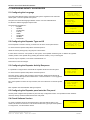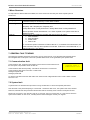
1
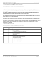
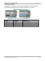
INFINITY ID2 ACTIVE REPEATER MANUAL.
Software Versions: 0.H.8682
ACTIVE REPEATER
INSTALLATION MANUAL
Approved Document No: GLT-221-7-1
Issue 1.0 Author: NRPJ
Date: 29/11/2013
PAGE 1
INFINITY ID2 ACTIVE REPEATER MANUAL.
Software Versions: 0.H.8682
CONTENTS
1.GENERAL INFORMATION ................................................................................ 3
1.1 Safety Information ...................................................................................3
1.2 Product Disposal At The End Of Its Working Life ......................................3
1.3 Environmental Information ......................................................................3
1.4 Equipment Guarantee .............................................................................. 3
2. Overview of the Infinity ID2 Active Repeater.................................................4
3. Repeater Access Levels ..................................................................................4
4. MOUNTING THE FIRE ALARM PANEL .............................................................5
4.1 FIXING THE BACK BOX TO THE WALL ........................................................5
4.2 Repeater connection ................................................................................6
5. CONFIGURING INFINITY ID2 REPEATER..........................................................7
5.1 Configuring the Language ........................................................................ 7
5.2 Configuring the Repeater Type and ID .....................................................7
5.3 Configuring the Repeater Activity Response ............................................7
5.3 Configuring the Repeater panel onto the Fire panel ................................7
5.4 Check Software Version ........................................................................... 7
6 Menu Structure ..............................................................................................8
7. GENERAL FAULT FINDING ..............................................................................8
7.1 Communication fault................................................................................8
7.2 System fault .............................................................................................8
8. PCB TERMINATION CONNECTIONS. ...............................................................9
9 SPECIFICATIONS............................................................................................ 10
9.1 Enclosure specifications ......................................................................... 10
9.2 Electrical specifications ......................................................................... 10
Approved Document No: GLT-221-7-1
Issue 1.0 Author: NRPJ
Date: 29/11/2013
PAGE 2
INFINITY ID2 ACTIVE REPEATER MANUAL.
Software Versions: 0.H.8682
1.GENERAL INFORMATION
1.1 Safety Information
Please consult the Infinity ID2 Installation manual for safety information relating to the ID2 System.
1.2 Product Disposal At The End Of Its Working Life
Like all electronic equipment, at the end of its working life this unit should not be disposed of in
a refuse bin. It should be taken to a local reprocessing site as per the guidelines of the WEEE
directive, for correct disposal.
1.3 Environmental Information
•
•
•
•
o
It will operate in ambient temperatures of –5 to 40 C
It will operate in a relative humidity of up to 95% (non condensing)
It will withstand vibrations between 5 & 150 Hz
The repeater should be maintained as described in section 3 of the Infinity ID2 User Manual, Maintenance Guide & Log
Book.
1.4 Equipment Guarantee
If this equipment is not fitted and commissioned according to our guidelines, and the relevant National Standards, by an
approved and competent person or organisation, the warrantee may become void.
Approved Document No: GLT-221-7-1
Issue 1.0 Author: NRPJ
Date: 29/11/2013
PAGE 3
INFINITY ID2 ACTIVE REPEATER MANUAL.
Software Versions: 0.H.8682
2. Overview of the Infinity ID2 Active Repeater
The Infinity ID2 active repeater is used on an Infinity ID2 Panel.
It is powered from the ID2 Panel, so is connected via 4 cores: 2 x power and 2 x data. Op to 8 repeaters can be
connected. The first 2 repeaters can be powered from the panel. Subsequent repeaters would need an external
power supply.
Each repeater can be selectively configured to determine which commands it will send to the network. EG to
allow some repeaters to reset the system, and others to not reset the system.
Each Repeater can also be configured to run in a different language (Although any device labels entered by the
installer will just be in the language entered)
The repeater shows Alarms and faults from the fire panel. It does not show disablements or test mode events.
The repeater can be configured to start panel sounders, stop panel sounders, Silence panel Buzzers and reset the
panel. The repeater can not interrogate panel configuration or device status. The repeater can not select
disablements or test mode.
3. Repeater Access Levels
The Infinity ID2 active repeater has the following access levels:Access Level
AL1
Access
Code
N/A
AL2
123
AL3
369
Available functions
View panel indications
Silence fault buzzer
Scroll between multiple event messages
Start Alarm Sounders (Evacuate)
Stop Alarm Sounders
Reset panel
Select Repeater Panel Language
Select Panel the repeater connects to
Select Repeater Number
Configure repeater response
•
Start Sounders
•
Stop Sounders
•
Reset Panel
•
Silence All
Approved Document No: GLT-221-7-1
Issue 1.0 Author: NRPJ
Date: 29/11/2013
PAGE 4
INFINITY ID2 ACTIVE REPEATER MANUAL.
Software Versions: 0.H.8682
4. MOUNTING THE FIRE ALARM PANEL
The Infinity ID2 Active Repeater comes with many cable entry holes. If another entry hole is required, it is strongly
recommended that the, the termination PCBs should be removed and stored in a safe place. This would also help while fixing
the back box to the wall.
4.1 FIXING THE BACK BOX TO THE WALL
Figure 2: Plan view inside the enclosure without PCBs. Side view for surface installation.
Fix the enclosure to the wall using the three mounting holes provided.
Check the build & condition of the wall to decide a suitable screw fixing.
The mounting holes are designed for No 8 roundhead or countersunk woodscrews (or similar).
Remove any debris from the enclosure.
Take care not to damage the FACP during installation.
Approved Document No: GLT-221-7-1
Issue 1.0 Author: NRPJ
Date: 29/11/2013
PAGE 5
INFINITY ID2 ACTIVE REPEATER MANUAL.
Software Versions: 0.H.8682
4.2 Repeater connection
The Infinity ID2 Plus Active repeater has an RS485 connection to an ID2 Repeater. The repeater has full control.
Up to 2 repeaters can be powered from the Aux 24V DC output on the panel. If 3 or more are to be connected,
then they must be powered from external 24V power supplies. The panel supports up to 8 repeaters.
ID2 PANEL
ID2 Panel
AUX 28V +
AUX 28V RS485 B
RS485 A
RS485 GND
ID2 REPEATER
ID2 Repeater
24V DC IN +
24V DC IN RS485 B
RS485 A
RS485 GND
Approved Document No: GLT-221-7-1
Issue 1.0 Author: NRPJ
Date: 29/11/2013
Description
Power for repeater
Power for repeater
Data connection
Data connection
Data connection screen
PAGE 6
INFINITY ID2 ACTIVE REPEATER MANUAL.
Software Versions: 0.H.8682
5. CONFIGURING INFINITY ID2 REPEATER
5.1 Configuring the Language
From the system Normal screen, press enter and type the engineer access code 369
Select Option 1 from the repeater set-up menu
The panel now shows the language selection screen. Use Prev & Next Buttons
To select the desires language and press enter.
The languages available are:English,
•
Spanish,
•
Portuguese,
•
French,
•
•
Italian,
Hungarian,
•
Serbian,
•
Lithuanian
•
5.2 Configuring the Repeater Type and ID
For the repeater to function correctly, it needs to be set to the correct panel version.
Infinity ID2/8 Zone
Repeater Panel 1
System Normal
24-09-2012 09:35
Repeater Setup
1: Language
2: Panel Type
3: Activity
Set Language
English
Press ENTER to Save
Panel Type
Infinity ID2/8 Zone
Repeater ID: 1
Press ENTER to Save
To do this enter the repeater setup Menu and select option 2.
Select the correct panel type by using the prev / Next buttons
If there will be more than one repeater on the system, each repeater should be given a different ID (repeater
number). Select a new repeater ID by pressing the relevant number (1 to 8) on the keypad.
If there is only one repeater, it can be left at the default ID of 1.
Press enter to save the changes.
5.3 Configuring the Repeater Activity Response
It is possible to configure which commands the repeater will send to the main panel.
To do this enter the repeater setup Menu and select option 2.
1:
2:
3:
4:
Start Sounders
Stop sounders
Reset Panel
Silence All
1:
2:
3:
4:
Start Sounders
Stop sounders
Reset Panel
Silence All
*
*
*
*
The menu gives 4 options: Start sounders, Stop sounders, Reset panel & silence All.
The currently selected options are marked with a *. Press the buttons 1 to 4 to toggle the
required options on or off.
Eg to set a repeater so that it can stop sounders, but not to start them or reset the system,
set as
*
*
Each repeater could have different settings if required
5.3 Configuring the Repeater panel onto the Fire panel
The ID2 panel configures the repeaters as part of the loop configuration routine. If a repeater has been added or
removed, the loop should be relearned from the main panel.
5.4 Check Software Version
To view the software version of the repeater panel, press the LED test button. This
needs to be done at access level 2. The screen will show the Type of panel the repeater
is configured for , and the software version
Approved Document No: GLT-221-7-1
Issue 1.0 Author: NRPJ
Date: 29/11/2013
Infinity ID2/8 Zone
0.H.8682
PAGE 7
INFINITY ID2 ACTIVE REPEATER MANUAL.
Software Versions: 0.H.8682
6 Menu Structure
To help locate the different features available, the menu structure of the Infinity ID2 Active repeater panel is
shown here.
MENU LAYOUT
1:Language
2:Panel Type
Choose between English, Spanish, Portuguese, French, Italian, Hungarian, Serbian,
Lithuanian with prev & next keys. Press enter to select
Select the panel this repeater is connected to with the Prev & Next Keys. Options are:Simplicity 126 / Simplicity 64 / Simplicity 252
Infinity ID2/2 Zone / Infinity ID2/4 Zone / Infinity ID2/6 Zone / Infinity ID2/8 Zone
3:Activity
Select repeater number with buttons 1 to 8. Each repeater on a system must have a
different number
Selects which commands the repeater will send to the main panel:1. Start sounders
2. Stop Sounders
3. Reset Panel
4. Silence All
A * means the option is selected. If Silence all has a *, it will silence its own buzzer, the
panel`s buzzer, and any other repeaters connected. If silence is not marked with a *, it
will just silence it`s own buzzer.
7. GENERAL FAULT FINDING
The Infinity ID2 repeater panel does not have any input or output circuits, so any General faults reported should
be investigated at the main panel. There are 2 possible faults which can be generated by the repeater itself
7.1 Communication fault
Communication fault means that the repeater cannot see the communications from
the main panel. The possible causes for this are:-
Infinity ID2/8 Zone
Repeater Panel 1
Communication Lost
Communication cable reverse polarity. It should be connected A to A and B to B
Communication cable loose connection or cable break
Damaged repeater PCB
Damaged panel PCB
To check a PCB, Disconnect the data cable. Then check the DC voltage between B and A with a DVM. It should
be around 1.5V
7.2 System fault
A system fault is an abnormal microprocessor running condition due to various unexpected phenomena.
This will result in the panel attempting to correct itself. Should this fault occur, the System Fault LED, General
Fault LED, General Fault relay and fault internal buzzer will be constantly active until the control panel is reset.
Disconnect the power to the repeater. Wait for 10 seconds, then turn power back on. This should cause the
system fault condition to clear. If not, it is likely that the PCB is damaged. Consult your supplier.
Approved Document No: GLT-221-7-1
Issue 1.0 Author: NRPJ
Date: 29/11/2013
PAGE 8
INFINITY ID2 ACTIVE REPEATER MANUAL.
Software Versions: 0.H.8682
8. PCB TERMINATION CONNECTIONS.
Connection No
Description
1
RS485
2
24VDC Input
No other connections are used
Use
Data Connection from ID2 panel
Power Connection from ID2 panel
Approved Document No: GLT-221-7-1
Issue 1.0 Author: NRPJ
Date: 29/11/2013
PAGE 9
INFINITY ID2 ACTIVE REPEATER MANUAL.
Software Versions: 0.H.8682
9 SPECIFICATIONS
9.1 Enclosure specifications
DESCRIPTION
VALUE
ENCLOSURE SIZE
TOP CABLE ENTRIES
364 x 302 x 90 mm
15 x 19mm DIA ENTRIES
9.2 Electrical specifications
ELECTRICAL DESCRIPTION
VALUE
SUPPLY VOLTAGE
OPERATING CURRENT
AUXILIARY FAULT OUTPUT
MAX NUMBER OF REPEATERS PER SYSTEM
REPEATER CONNECTION
29V DC Nominal (19 to 30V DC)
40mA typical
1 x FAULT RELAY SELV@1A (NORM. ENERG)
8
RS485
Approved Document No: GLT-221-7-1
Issue 1.0 Author: NRPJ
Date: 29/11/2013
PAGE 10
INFINITY ID2 ACTIVE REPEATER MANUAL.
Software Versions: 0.H.8682
Installation Manual Modification History
ISSUE
DATE
1.0
29/11/2013
CHANGES
Initial Release
Approved Document No: GLT-221-7-1
Issue 1.0 Author: NRPJ
Date: 29/11/2013
PAGE 11