1
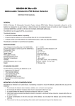
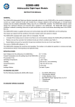
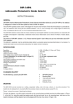
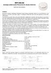
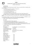
S2000-AR2
Addressable Double-Input Module
INSTRUCTION MANUAL
GENERAL
The S2000-AR2 Addressable Double-Input Module (hereinafter referred to as the S2000-AR2 or the module) is designed
to connect one or two monitored circuits with included dry contact (both NO and NC) fire or intrusion detectors into the
multiplex addressable Polling Loop (PL) of a S2000-KDL controller. The S2000-AR2 receives control signals from
interfaced detectors and transmits alarm conditions to the S2000-KDL.
The S2000-AR2 module is supplied with power and communicates data with the S2000-KDL over the polling loop.
The version of the AR2 software is 1.00.
The S2000-AR2 supports DPLS_v2.xx data communication protocol providing measuring voltage of the polling loop at the
point of its location.
The S2000-AR2 is designed for round-the-clock operating. The module is not suitable for operation in corrosive and dusty
environments as well as in fire-hazardous and explosive areas.
INDICATION
The S2000-AR2 is equipped with a red LED on its cover.
LED behavior depends on zone parameters programmed for this S2000-AR2 in the S2000-KDL configuration (to give
more information please refer to the S2000-KDL Manual). The given Device Indication Control parameter defines whether
the LED will operate in accordance with its own local tactics, or with the logic of the master S2000-KDL. The indication
can also be disabled by the S2000-KDL at all.
LED indication depending on the S2000-KDL logic is described in the S2000-KDL Manual.
The local S2000-AR2 indication tactics is as follows:
LED doesn’t light
No power is supplied via the polling loop
LED is lit steady
The module has been supplied with power but the S2000-KDL has not yet
polled the module
LED flashes once per four
Both monitored circuits are in Norm conditions (see Table 1)
seconds
LED double flashes once per
One or both monitored circuits are out of norm (see Table 1). Depending on
four seconds
the value of the Zone Type parameter (programmed for this S2000-AR2 in the
S2000-KDL configuration), this can mean fire, intrusion, or trouble conditions
LED quadruple flashes once
The S2000-KDL has switched the S2000-AR2 into the Address Programming
per four seconds
Mode
SPECIFICATIONS
Input Voltage (over the polling loop of a S2000-KDL)
8 ÷ 10 VDC
Current Consumption (over the polling loop of the S2000-KDL)
1 mA max
Pre-operation Time
15 s max
Operating Temperatures
−30 to +50°C
Transport / Storage Temperatures
−50 to +50°C
Ingress Protection Rating
IP41
Humidity
93% at 40°C, non-condensing
Overall Dimensions
56 mm × 33 mm × 20 mm max
Weight
40 g max
Average Lifetime
at least 10 years
STANDARD DELIVERY
Find the following unpacking the S2000-AR2:
S2000-AR2 Module
2 EOL Resistors MF 1/4W-10k-5%
2 Woodscrews
2 Wallplugs
This Instruction Manual (one per ten S2000-AR2)
STANDARD WIRING DIAGRAMS
The Figure 1 below shows wiring the S2000-AR2 to the polling loop of the S2000-KDL as well as standard variants for
wiring non-addressable (conventional, zone-type, dry contact) detectors to the S2000-AR2 monitored circuit (detector
loop) contacts DL1 and DL2.
D1
.
.
R1
Addr.
Det.
Addr.
Det.
Variant A
D1: fire detector with NC contact
S2000-AR2
-PL
+PL
.
.
.
.
S2000-KDL
REOL
.
.
-PL
+DL2
+PL
-DL2
-PL
-DL1
+PL
+DL1
Zone-Type
Detector,
Variant A, B, or C
.
D2
REOL
Zone-Type
Detector,
Variant A, B, or C
R2
.
Variant B
D2: fire detector with NO contact
.
D4
D3
REOL
.
Variant C
D3: intrusion detector with NO contact
D4: intrusion detector with NC contact
Figure 1. Standard Wiring Diagrams
Variant A is for wiring fire detectors with normally closed contacts, Variant B is for wiring fire detectors with normally open
contacts, and Variant C is used for wiring intrusion detectors with both normally open and normally closed contacts.
Reol is for EOL Resistors MF 1/4W-10k-5% provided while R1 and R2 are additional resistances MF 1/4W-20k-5% and MF
1/4W-4.7k-5% respectively.
You can wire several conventional dry contact detectors into a single monitored circuit. The number of the detectors to be
included is defined by the requirement that resistance of a monitored circuit wired in accordance with Variants A − C must
match its physical conditions as shown in Table 1 (see below).
Variants A and B provide connecting fire detectors and recognizing such conditions of a monitored circuit as Norm, Fire
Alarm, Open Failure, and Short Failure provided that the monitored circuit is programmed in S2000-KDL configuration as
the Combined Fire Alarm Loop (Type 2) - see below.
If intrusion detectors are interfaced to the polling loop of the S2000-KDL in accordance with Variant C, the relevant
monitored circuit (detector loop) should be configured as the Intrusion Alarm Loop (Type 4), or Auxiliary Alarm Loop (Type
6), or Entrance Alarm Loop (Type 7), or Panic Alarm Loop (Type 11) – see below. In such a case the S2000-KDL
recognizes such circuit conditions as Norm and Intrusion Alarm.
MOUNTING
Hang the S2000-AR2 on a wall by means of the woodscrews provided. The drilling pattern
is shown in Figure 2.
Connect PL contacts of the S2000-AR1 to the relevant polling loop wires. Connects
47
monitored circuits DL1 and DL2 to the NO or NC contacts of the relevant detectors. Bring
EOL resistors and (if necessary) additional resistors into monitored circuits in accordance
with the selected wiring schemes. Please keep in mind that the resistance of each
monitored circuit without regard to EOL resistor should NOT exceed 100 Ω while leakage
resistance should be at least 50 kΩ.
Figure 2. Drilling Pattern
PROGRAMMING
In order the S2000-AR2 operates properly within the multiplex addressable polling loop of the S2000-KDL controller, the
module must be assigned to a unique number from 1 to 126 within the polling loop, or the loop address which is stored in
the module non-volatile memory. The S2000-AR2 occupies two adjacent loop addresses. The address is assigned to the
first monitored circuit of the module, the second monitored circuit being assigned automatically to the incremented
number. The default factory value of the S2000-AR2 loop address is 126 / 127.
Moreover, a monitoring strategy must be defined which will be used by the S2000-KDL controller while processing signals
received from the S2000-AR2.
Programming the S2000-AR2 Address within the S2000-KDL Polling Loop
An S2000-AR2 module is supplied with the default loop address of 126 / 127. This address value can be changed using
either S2000(M) console tools or the UProg Configuration Tool.
In order to program the unique S2000-AR2 loop address, connect the module to a S2000-KDL controller which is in turns
connected to a network controller (a S2000(M) console or PC under UProg software). Then send one of the following
commands to the S2000-KDL controller (for getting more information see the relevant User’s Manual):
Change the Device Address
Use the Change Device Address command specifying the old module address and the
new module address as the parameters (see more information in the referred Manuals).
The network controller will display the messages about disconnecting the device with the
old address and then detecting the device with newly programmed address
Program the Device Address
If the device address is unknown or two devices have the same address then use the
Program Device Address command specifying a required address as the parameter.
Then open the module enclosure and press the button on the PCB three times long
(more than 1 s each) and then one time short (less than half second). The address will
be assigned to the first detector loop of the S2000-AR1, the second detector loop being
automatically assigned to an incremented number. The message about detecting the
device with the newly assigned address shall be displayed by a network controller
(S2000(M) or UProg Configuration Tool).
Please be attentive to avoid configuration conflicts.
Programming the S2000-KDL to Operate the S2000-AR2
To handle signals from a S2000-AR2 correctly, the S2000-KDL controller the module is connected to must be
programmed with the proper Zone Type parameters for this S2000-AR2.
To program the S2000-KDL, connect it to a PC under UProg Configuration Tool and follow the relevant programming
instructions in accordance with the S2000-KDL User’s Manual. Set Zone Type parameter to the value 2 (Combined Fire
Alarm Loop) for fire detectors and to one of the values 4 (Intrusion Alarm Loop), 6 (Auxiliary Alarm Loop), 7 (Entrance
Alarm Loop), or 11 (Panic Alarm loop) for intrusion detectors.
S2000-AR2 ROUTINE TESTING
Test the S2000-AR2 module by doing the following.
Step 1. Arm the first monitored circuits with brought detectors by means of a network controller (either S2000/S2000M
console or Orion PC).
Step 2. Simulate the detector response. Ensure the module LED double flashes once per four seconds while the network
controller indicates a Fire Alarm or Intrusion Alarm message for this monitored circuit.
Step 3. Recover normal conditions and ensure the module LED returns to single flashing once per four seconds.
Step 4. Reset the alarm by means of the network controller.
Repeat Steps 1 to 4 for the second monitored circuit of the S2000-AR2 module.
If the network controller has displayed no intrusion or fire condition messages said above or the module indication differs
from that said above then the module is defective and must be replaced.
You can additionally inspect the parameters of the monitored circuits having measured their ADC values which correlate
with resistance values of the monitored circuits (see Table 1 below).
Table 1. Match between monitored circuit resistances (or ADC value) and statuses of the monitored circuits
Short circuit
or D3 response
(Variant C)
D2 response
(Variant B)
Norm
D1 response
(Variant A)
Open failure
or D4 response
(Variant C)
Resistance, kΩ
0 to 1.9
2.5 to 6.2
6.5 to 14
15 to 46
50 and above
ADC value
0 to 10
12 to 29
31 to 58
63 to 121
125 to 230
ZAO NVP Bolid, 4 Pionerskaya Str., Korolev 141070, Moscow Region, Russia
Phone/fax: +7 495 513-32-35
Email: [email protected], [email protected]
www.bolid.com
BOLID ONE YEAR LIMITED WARRANTY
Bolid Company and its divisions and subsidiaries («Seller»), 4 Pionerskaya Str., Korolev 141070, Moscow Region, Russia warrants its
security equipment (the «product») to be free from defects in materials and workmanship for one year from date of original purchase,
under normal use and service. Seller’s obligation is limited to repairing or replacing, at its option, free of charge for parts or labor, any
product proven to be defective in materials or workmanship under normal use and service. Seller is not responsible for results where
the product is used improperly, where it is used for any application it is not intended for, used under unacceptable environmental
conditions and mishandled or stored under improperly. Seller shall have no obligation under this warranty or otherwise if the product is
altered or improperly repaired or serviced by anyone other than the Seller. In case of defect, contact the security professional who
installed and maintains your security equipment or the Seller for product repair.
This one year Limited Warranty is in lieu of all other express warranties, obligations or liabilities. There are no express warranties,
which extend beyond the face hereof. Any implied warranties, obligations or liabilities made by seller in connection with this product,
including any implied warranty of merchantability, or fitness for a particular purpose or otherwise, are limited in duration to a period of
one year from the date of original purchase. Any action for breach of any warranty, including but not limited to any implied warranty of
merchantability, must be brought within 12 months from date of original purchase. In no case shall seller be liable to anyone for any
consequential or incidental damages for breach of this or any other warranty, express or implied, or upon any other basis of liability
whatsoever, even if the loss or damage is caused by the seller’s own negligence or fault. Some countries do not allow limitation on how
long an implied warranty lasts or the exclusion or limitation of incidental or consequential damages, so the above limitation or exclusion
may not apply to you.
Seller does not represent that the product may not be compromised or circumvented; that the product will prevent any personal injury
or property loss by burglary, robbery, fire or otherwise; or that the product will in all cases provide adequate warning or protection.
Buyer understands that a properly installed and maintained alarm may only reduce the risk of a burglary, robbery, fire or other events
occurring without providing an alarm, but it is not insurance or guarantee that such will not occur or that there will be no personal injury
or property loss as a result. CONSEQUENTLY, SELLER SHALL HAVE NO LIABILITY FOR ANY PERSONAL INJURY, PROPERTY
DAMAGE OR OTHER LOSS BASED ON A CLAIM THE PRODUCT FAILED TO GIVE WARNING. HOWEVER, IF SELLER IS HELD
LIABLE, WHETHER DIRECTLY OR INDIRECTLY, FOR ANY LOSS OR DAMAGE ARISING UNDER THIS LIMITED WARRANTY OR
OTHERWISE, REGARDLESS OF CAUSE OR ORIGIN, SELLER’S MAXIMUM LIABILITY SHALL NOT IN ANY CASE EXCEED THE
PURCHASE PRICE OF THE PRODUCT, WHICH SHALL BE THE COMPLETE AND EXCLUSIVE REMEDY AGAINST SELLER. This
warranty gives you specific legal rights, and you may also have other rights which vary from country to country. No increase or
alteration, written or verbal, to this warranty is authorized.