1
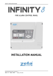
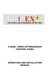
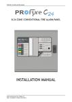
Instruction Manual
INSTRUCTION MANUAL: 1-2 ZONE FIRE ALARM PANEL
INDEX
INDEX ...........................................................................................................................2
Introduction....................................................................................................................3
Mains & Battery.............................................................................................................4
Connecting the mains.................................................................................................4
Connecting the batteries.............................................................................................4
Detectors & sounders.....................................................................................................5
Wiring the detectors...................................................................................................5
Wiring the sounders ...................................................................................................5
Display & Controls ........................................................................................................6
Display .......................................................................................................................6
Controls......................................................................................................................7
Alarm Condition & Resetting an alarm .........................................................................8
What to do in the event of a fire. ...............................................................................8
Resetting from an alarm condition.............................................................................8
Fault display & fault-finding .........................................................................................9
Fault Finding..............................................................................................................9
Supply fault............................................................................................................9
Zone Fault ............................................................................................................10
Sounder Circuit Fault...........................................................................................10
Battery Calculation ......................................................................................................11
Sample Calculation ..................................................................................................11
Specifications...............................................................................................................12
Electrical Specifications...........................................................................................12
Enclosure Specifications..........................................................................................12
Fuse Ratings.............................................................................................................12
Log Book .....................................................................................................................13
MAINTENANCE WORK .......................................................................................13
FALSE ALARMS....................................................................................................14
ALL OTHER EVENTS ...........................................................................................15
Approved Document No: GLT.MAN-118
Issue : 1.1
Author: NRPJ Date: 22/11/2006
PAGE 2
INSTRUCTION MANUAL: 1-2 ZONE FIRE ALARM PANEL
Introduction
The Premier Elite 1 & 2 zone panels have been designed to meet the
requirement of a low cost easy to use fully functional fire alarm control panel.
It is available as either a 1 zone panel, or a 2 zone panel.
Each version has 2 sounder circuits, and an alarm relay.
There is no configuration, simply connect the detectors & sounders and apply
power.
The Premier Elite range also includes 4,6 and 8 zone panels. These panels
are NOT covered in this manual. They have a separate manual.
The 4,6 & 8 zone panels have the option to fit a hard wired repeater, as well
as having a fault output, and a sounder delay option.
Approved Document No: GLT.MAN-118
Issue : 1.1
Author: NRPJ Date: 22/11/2006
PAGE 3
INSTRUCTION MANUAL: 1-2 ZONE FIRE ALARM PANEL
Mains & Battery
Connecting the mains.
The Mains supply to the FACP is fixed wiring, using Fire resisting 3-core
cable (Between 1 mm² and 2.5mm²) or a suitable 3-conductor system, fed
from an isolating double pole switch fused spur, fused at 3A. IT SHOULD
NOT BE CONNECTED THROUGH AN RCD. This should be secure from
unauthorised operation and be marked ‘FIRE ALARM: DO NOT SWITCH
OFF’. The supply must be exclusive to the Fire Panel. MAKE SURE ANY
SPARE ENTRY HOLES ARE COVERED WITH THE GROMMETS
PROVIDED
Connecting the batteries
The Premier Elite requires 2 x 12 V sealed lead acid (SLA) batteries
The two batteries are wired in series.
The +ve of one battery is connected to the red battery lead.
The –ve of the other battery is connected to the black battery lead.
The –ve of the first battery is connected to the +ve of the second battery using
the link wire supplied.
Although there are many sizes of suitable battery, the sizes we usually
recommend are 12V 2Ah for standard backup, or 12V 7Ah for extended
backup (72 hour or more) , and the enclosure has been designed to hold
these two battery sizes.
BATTERY
INTERCONNECTING
CABLE
TO PCB
BATTERY
INTERCONNECTING
CABLE
2 x 2Ah Batteries
SEALED LEAD ACID BATTERY
TO PCB
CLAMP
SEALED LEAD ACID BATTERY
SEALED LEAD ACID BATTERY
12V / 7 Ah
12V / 7Ah
12V / 2 Ah
Approved Document No: GLT.MAN-118
Issue : 1.1
Author: NRPJ Date: 22/11/2006
PAGE 4
INSTRUCTION MANUAL: 1-2 ZONE FIRE ALARM PANEL
Detectors & sounders
Wiring the detectors
The Premier Elite has been designed to use a 10K resistor end of line on the
detector zones.
Zone -R
L2
-R
L2
L2
EARTH
EARTH
T
OU
L1
L1
IN
UT
EARTH
O
L1
-R
O
L1
L1
IN
L1
UT
IN
Zone +
Call points should be connected to the start of the zone, so that removing a
detector head will not remove power from the call points.
Also note that detector bases with a continuity diode will not be compatible
with this panel. The diode should be removed to allow detector head removal
indicator to work.
Wiring the sounders
The Premier Elite has 2 sounder circuits with a combined rating of 800mA.
Each sounder circuit must be fitted with a 10k end of line resistor
SND+
SND-
SOUNDER
++
--
SOUNDER
++
--
Approved Document No: GLT.MAN-118
Issue : 1.1
Author: NRPJ Date: 22/11/2006
SOUNDER
++
--
SOUNDER
++
--
10K
End of
Line Resistor
PAGE 5
INSTRUCTION MANUAL: 1-2 ZONE FIRE ALARM PANEL
Display & Controls
Here is the fascia for the Premier Elite.
Operating Instructions
Normal Operation:
Under normal conditions, the system will be silent and the green
"POWER" LED will be on.
Fire Condition:
In a fire condition, the "GEN FIRE" LED and the specific zones(s)
"FIRE" LED will be on and the internal panel buzzer will sound.
Fault Condition:
In any fault condition, the "GEN FAULT" LED and the specific zone
fault(s) LED will be on and the internal fault buzzer will sound.
Disabled Condition:
In the disabled condition, the "GEN DISABLEMENT" LED and the
specific zone(s) LED will be on.
Start/Stop Fire Sounders:
To start or stop the fire sounders, turn the key switch to the
"CONTROLS ENABLED" position and press button 1 . Pressing
this button again will toggle between stop/start sounders.
To Reset From Fire Condition:
After all detectors and manual call points have been
returned to normal, turn the key switch to the "CONTROLS
ENABLED" position and press button 1 to stop the fire
sounders. Press button 2 to silence the internal fault buzzer
and then press button 3 to RESET the system.
Silence Fault Tone
If the panel is showing a fault condition, turn the key
switch to the "CONTROLS ENABLED" position and press
button 2 (SILENCE FAULT CONDITION). If new faults are
subsequently detected, the specific fault(s) LED will be
on and the internal fault buzzer will sound. CALL
ENGINEER.
External Sounder Delay Override:
When the panel is in a Fire Condition and the system has been configured
with delayed alarm function, the "DEL" LED will be on. At the end of the delay
period the "DEL" LED will go off and the fire sounders will then operate. This
delay may be overridden by pressing the “DELAY OVERRIDE" button.
Elite
FIRE ALARM CONTROL PANEL
DESIGNED TO EN54 PARTS 2 & 4
FAULT TONE
Display
The Premier Elite has the following LED indicators:LED
COLOUR MEANING
POWER
GREEN
GEN FIRE
GEN FLT
RED
YELLOW
SUPPLY FLT
YELLOW
FLT
FIRE 1
FAULT 1
YELLOW
RED
YELLOW
FIRE 2
FAULT 2
RED
YELLOW
The system has mains and/or battery backup present. The
panel showing this LED only is the normal condition
There is an alarm on the system.
There is a fault on the system. Check specific LED for further
information. (Note: Not available on Premier Elite 1 zone.
There is a problem with either mains supply, or battery
backup
There is a fault on one of the sounder circuits
There is a fire on zone 1
There is a fault in the wiring on zone 1, or a detector has
been removed
There is a fire on zone 2
There is a fault in the wiring on zone 2, or a detector has
been removed
Approved Document No: GLT.MAN-118
Issue : 1.1
Author: NRPJ Date: 22/11/2006
PAGE 6
INSTRUCTION MANUAL: 1-2 ZONE FIRE ALARM PANEL
Controls
The Premier Elite has the following controls:BUTTON
1
LABEL
START/STOP
2
SILENCE FAULT TONE
3
RESET
4
LED TEST
USE
Used to silence the sounders in an alarm, or to
manually start the sounders to evacuate building
Used to silence the panel`s internal buzzer in a fault
or alarm condition.
Used to return the panel to its normal condition after
an ALARM condition. (Reset will not clear faults)
To check that all indicator LEDs are working. Use as
part of the daily / weekly fire alarm inspection.
Note that the controls can only be used after the keyswitch has been turned to
the ON position.
Approved Document No: GLT.MAN-118
Issue : 1.1
Author: NRPJ Date: 22/11/2006
PAGE 7
INSTRUCTION MANUAL: 1-2 ZONE FIRE ALARM PANEL
Alarm Condition & Resetting an alarm
The Premier Elite signals an alarm by the following:Turn on the General Fire LED
Turn on the Zonal Fire Indicator
Turn on internal buzzer
Start any sounders connected to the panel`s sounder circuits
Activate the fire relay (if fitted)
What to do in the event of a fire.
1. Follow the building evacuation procedure, and check that everyone has
left the building safely.
2. The building fire officer or responsible person should CAREFULLY
enter the building, and locate the area of the alarm from the fire alarm
panel.
3. Investigate to determine the cause of the alarm. Look for the detector
in the zone in alarm that signalled the fire. The detector that signalled
an alarm will have its RED ALARM LED on.
4. If a small fire is found, a suitably trained person could tackle this with a
suitable fire extinguisher.
5. If a larger fire is found, leave the building immediately, and contact the
fire brigade.
6. If no fire is found, make a note of the detector that signalled fire, and
look for anything nearby that could be the cause of the activation, eg
cooking, or use of a hot air gun etc.
7. Record findings in the fire alarm log book.
Resetting from an alarm condition
After the relevant action has been taken, the Premier Elite fire alarm panel can be reset by
the following:1
2
3
Press Stop/Start sounder button (BUTTON 1). This will silence the external
sounders.
Press Silence Fault Tone button (BUTTON 2). This will silence the panel`s
internal buzzer.
Press the Reset button (BUTTON 3). This will return the panel to it`s normal
condition.
If the panel goes straight back into alarm, then the cause of the alarm has not been
cleared. This could be a detector still exposed to smoke, or a call point still in the active
position. Press Buttons 1 & 2 on the panel, then investigate for a call point, or detector
that still has it`s RED ALARM LED on. Reset the call point, or clear the smoke. If the
problem persists, contact an engineer.
Approved Document No: GLT.MAN-118
Issue : 1.1
Author: NRPJ Date: 22/11/2006
PAGE 8
INSTRUCTION MANUAL: 1-2 ZONE FIRE ALARM PANEL
Fault display & fault-finding
The Premier Elite 1 & 2 zone panels monitor for the following faults:Low or failed mains (Including fuses)
Low or failed battery (Including fuse)
Detection Zone open circuit wiring fault
Detection Zone short circuit wiring fault
Detection Zone detector removed.
Sounder circuit open circuit wiring fault
Sounder circuit short circuit wiring fault
The Premier Elite 2 zone panel also has a General Fault LED that will light
when any fault is present.
Most of these faults will need to be checked by an engineer, but the system
can be checked for a removed detector by the responsible person..
All faults in the Premier Elite are NON-LATCHING. IE they can not be reset
with the reset button. They will clear automatically when the fault has been
fixed.
Fault Finding
Supply fault
A power supply fault is indicative of one or more of the following faults: Loss of Mains power
•
•
•
•
Check that 230V AC is present at the mains terminal block
Check mains fuse
Check that there is 30-34V coming from the transformer secondary
Check charger fuse FS1.
Loss of Battery power
•
•
•
•
Check that 2 X 12V batteries are fitted in series to give 24V backup
Check battery fuse FS2.
Check that battery connections are secure.
Check that the batteries are not over 5 years old
Approved Document No: GLT.MAN-118
Issue : 1.1
Author: NRPJ Date: 22/11/2006
PAGE 9
INSTRUCTION MANUAL: 1-2 ZONE FIRE ALARM PANEL
Zone Fault
A Zone Fault is indicative of one or more of the following faults:Open Circuit fault.
•
•
•
•
•
•
Check that the correct end of line resistor (10K) has been fitted
Check that there are no breaks in the cable, and that all screw connections are
secure.
Check that no detectors have been removed from the circuit.
Check that all detectors are correctly fitted to the base.
As a cable check, remove zone wire from panel & measure resistance. Should
read 10k end of line resistance. (If a break is found, splitting the line in half &
fitting EOL will help determine which section of cable has the fault)
As a panel check, remove cable & fit EOL at the panel. If the fault clears, the
panel is working correctly.
Short Circuit Fault
•
•
•
•
•
Check that the correct end of line has been fitted (10k resistor)
Check that no equipment, other than detectors or call points has been fitted to the
zone.
Check for shorts to the cable screen.
Check that none of the heads have become damaged (remove one at a time).
As a panel check, remove cable & fit EOL at the panel. If the fault clears, the
panel is working correctly.
Sounder Circuit Fault
A Sounder Fault is indicative of one or more of the following faults:Sounder Open Circuit fault.
•
•
•
•
Check that the correct end of line resistor (10K) has been fitted
Check that sounder fuse FS3 is intact.
Check that there are no breaks in the cable, and that all screw connections are
secure.
As a panel check, remove both circuits cable & fit both EOLs at the panel. If the
fault clears, the panel is working correctly.
Short Circuit Fault
•
•
•
•
Check that the correct end of line has been fitted (10k resistor)
Check that ALL sounders, Bells etc are POLARISED, and are fitted the correct
way round. (see diagram after list)
Check for shorts to the cable screen.
As a panel check, remove cable & fit EOL at the panel. If the fault clears, the
panel is working correctly.
SND+
Note: If non-polarised
alarm devices (eg some
POLARISING
types of old mechanical
DIODE
SNDbell, or a relay) are
BELL
BELL
BELL
RELAY
10K
used, then a diode will
End of
++ - ++ - ++ - have to be placed in line
Line Resistor
with the device to
BACK EMF
enable fault monitoring.
DIODE
They may also need a
back EMF protection diode. (symptoms: Chattering sounder relays that don’t turn off).
CONNECTOR
BLOCK
NC
CM
NO
Approved Document No: GLT.MAN-118
Issue : 1.1
Author: NRPJ Date: 22/11/2006
PAGE 10
INSTRUCTION MANUAL: 1-2 ZONE FIRE ALARM PANEL
Battery Calculation
Here are the current consumption of the Premier Elite panels in various
conditions:Control Panel Model
Mains Fail,
Mains Fail,
Mains fail,
buzzer sounding
buzzer silenced panel in alarm
Premier Elite 1 Zone
48mA
28mA
113mA
Premier Elite 2 Zone
66mA
46mA
99mA
Sample Calculation
A Premier Elite 2 zone panel has the following items connected:Zone 1: 2 x MCP, 4 x Optical, 2 x heat detector
Zone 2: 1 x MCP, 7 x Optical, 1 x heat detector
Sounder CCT 1: 2 x Maxitone sounder
Sounder CCT 2: 4 x Maxitone sounder
ITEM
PREMIER ELITE 2
MCP
OPTICAL
HEAT
MAXITONE SOUNDER
QUIESCENT
66mA
0mA
100uA
50uA
0mA
ALARM
99mA
40mA
40mA
40mA
25mA
To calculate the required battery backup required, we use the equation:Battery Size (Standby time in Amp Hours) = 1.25 x [(TALM x IALM) + (TSBY x ISBY )]
Where:
TALM = Maximum time in hours required for the alarm [½ hour is most common time]
IALM = Total Alarm Current in amps for all alarm devices connected to the alarm circuits
TSBY = Standby time in hours for the system after mains failure [normally 24, 48 or 72 hr]
ISBY = Quiescent current in amps of control panel in fault condition [because of mains failure]
PLUS all detection zones.
IALM = PREMIER ELITE ALM + 6 X MAXITONE ALARM + 1 X DETECTOR ALM + 3 X MCP QU + 10 X
OPT QU + 3 x HT QU
=0.099 + 6x 0.025 + 1x 0.040 + 3x0 + 10x0.0001 + 3x0.00005
=0.099 + 0.15 + 0.04 + 0 + 0.0010 + 0.00015
=0.29015 Amps
ISBY = PREMIER ELITE QU + 6 X MAXITONE QU + 3 X MCP QU + 11 X OPT QU + 3 x HT QU
=0.066 + 6x0 + 3x0 + 11x0.0001 + 3x0.00005
=0.066 + 0 + 0 + 0.0011 + 0.00015
=0.06725
Therefore:Battery size
= 1.25 X ((0.5 x 0. 29015) + (24 x 0. 06725))
= 1.25 X (0.145075 + 1.614)
= 1.25 x 1.759075
= 2.19884 Ah
So 2.2 Ah batteries will be suitable for this installation.
Approved Document No: GLT.MAN-118
Issue : 1.1
Author: NRPJ Date: 22/11/2006
PAGE 11
INSTRUCTION MANUAL: 1-2 ZONE FIRE ALARM PANEL
Specifications
Electrical Specifications
ELECTRICAL DESCRIPTION
VALUE
MAINS VOLTAGE
BATTERY VOLTAGE
CHARGER SIZE
ZONE VOLTAGE (NO EOL FITTED)
SOUNDER ALARM OUTPUTS
AUXILIARY FIRE OUTPUT
NUMBER OF ZONES
MAXIMUM ZONE CAPACITY
ZONE END OF LINE DEVICE
SOUNDER END OF LINE DEVICE
CHARGER VOLTAGE
MAINS FAILED CURRENT (BUZZER ON)
MAINS FAILED CURRENT (BUZZER OFF)
230V AC +/- 10% @ 50/60 Hz
24V DC (2 X 12V SLA BATTERY)
1 AMP
21V DC NOMINAL (20 - 22.5V)
2 x 400mA @ 24V DC (Nominal)
1 x RELAY SELV (1A MAX)
1 or 2
20 DEVICES PER ZONE
10 K RESISTOR
10 K RESISTOR
27.6V DC (NO BATTERY CONNECTED)
48mA (1 ZONE) / 66mA (2 ZONE)
28mA (1 ZONE) / 46mA (2 ZONE)
Enclosure Specifications
DESCRIPTION
VALUE
ENCLOSURE SIZE
TOP CABLE ENTRIES
BOTTOM CABLE ENTRIES
REAR CABLE ENTRIES
355 x 275 x 100 mm
12 x 19mm DIA GROMMETED ENTRIES
2 x 19mm KNOCKOUT ENTRIES
2 SNAP OUTS, 60 x 20mm
Fuse Ratings
FUSE NO
FS1
FS2
FS3
INLET FUSE
DESCRIPTION
Charger Fuse
Battery Fuse
Sounder circuit)
Mains Protection Fuse
Approved Document No: GLT.MAN-118
Issue : 1.1
Author: NRPJ Date: 22/11/2006
RATING
1.6A time delay 5 x 20mm glass
1.6A time delay 5 x 20mm glass
800mA time delay 5 x 20mm glass
2A Quick Blow HBC 5 x 20mm ceramic
PAGE 12
INSTRUCTION MANUAL: 1-2 ZONE FIRE ALARM PANEL
Log Book
MAINTENANCE WORK
DATE TIME ZONE / LOCATION
REASON FOR WORK
Approved Document No: GLT.MAN-118
Issue : 1.1
Author: NRPJ Date: 22/11/2006
WORK CARRIED OUT
ADDITIONAL WORK REQUIRED
SIGNED
PAGE 13
INSTRUCTION MANUAL: 1-2 ZONE FIRE ALARM PANEL
FALSE ALARMS
DATE
TIME ZONE /
LOCATION
CAUSE (IF KNOWN)
OR ACTIVITIES IN
ALARM AREA
Approved Document No: GLT.MAN-118
Issue : 1.1
Author: NRPJ Date: 22/11/2006
MAINTENANCE
VISIT NEEDED
(YES/NO)
MAINTENANCE
FINDINGS
CATEGORY OF FURTHER
FALSE ALARM ACTION
REQUIRED
SIGNED
PAGE 14
INSTRUCTION MANUAL: 1-2 ZONE FIRE ALARM PANEL
ALL OTHER EVENTS
DATE
TIME
ZONE / LOCATION
DETAILS OF EVENT
(INCLUDING CAUSE IF KNOWN)
Approved Document No: GLT.MAN-118
Issue : 1.1
Author: NRPJ Date: 22/11/2006
ACTION
REQUIRED
DATE
COMPLETED
INITIALS
PAGE 15