1
CW25-TIM
Bulletin
Revision
Date
NS18-DS
07
26 March 2009
NS18-DSCW25-TIM
Copyright ©2009 NavSync Ltd. All Rights Reserved
Rev 07
Date: 03/26/09
Specifications subject to change without notice.
TABLE OF CONTENTS
1
INTRODUCTION------------------------------------------------------------------------ 4
2
SPECIFICATION------------------------------------------------------------------------ 6
2.1
2.2
2.3
2.4
Performance ------------------------------------------------------------------------------ 6
Recommended Ratings------------------------------------------------------------------ 7
Absolute Maximum Ratings-------------------------------------------------------------- 7
Block Diagram---------------------------------------------------------------------------- 7
3
PHYSICAL CHARACTERISTICS------------------------------------------------------ 8
3.1
3.2
3.3
Physical Interface Details---------------------------------------------------------------- 8
CW25-TIM Dimensions------------------------------------------------------------------- 9
Solder Pad Size and Placement--------------------------------------------------------- 9
4
SIGNAL DESCRIPTION---------------------------------------------------------------11
4.1
4.2
4.3
4.4
4.5
Power Signals----------------------------------------------------------------------------11
RF Signals--------------------------------------------------------------------------------12
Emulation/Test Signals------------------------------------------------------------------12
Control Signals---------------------------------------------------------------------------13
I/O Signals--------------------------------------------------------------------------------13
5
SPECIAL FEATURES------------------------------------------------------------------15
5.1
5.2
5.3
User Commands-------------------------------------------------------------------------15
Self-Survey ------------------------------------------------------------------------------15
CW25-TIM Embedded Identification---------------------------------------------------15
6
TAPE AND REEL SPECIFICATIONS-------------------------------------------------16
7
SOLDER PROFILE--------------------------------------------------------------------16
8
DEMO KIT INFORMATION------------------------------------------------------------16
9
APPLICATION HINTS-----------------------------------------------------------------17
9.1
9.2
9.3
9.4 9.5
9.6
9.7
9.8
Power Supply----------------------------------------------------------------------------17
RF Connection---------------------------------------------------------------------------17
Grounding--------------------------------------------------------------------------------18
Battery Backup--------------------------------------------------------------------------18
Over Voltage & Reverse Polarity Protection-------------------------------------------19
LEDs--------------------------------------------------------------------------------------19
Reset Generation------------------------------------------------------------------------19
Boot Options-----------------------------------------------------------------------------19
NS18-DSCW25-TIM
Rev 07
Copyright ©2009 NavSync Ltd. All Rights Reserved
Date: 03/26/09
Specifications subject to change without notice.
Figure and Table Contents
List of Figures
Figure 1 CW25-TIM Block Diagram--------------------------------------------------------------------- 7
Figure 2 CW25-TIM Form and Size--------------------------------------------------------------------- 8
Figure 3 CW25-TIM Dimensions------------------------------------------------------------------------ 9
Figure 4 Solder Pad Size and Placement--------------------------------------------------------------10
Figure 5 RF Tracking Example--------------------------------------------------------------------------17
Figure 6 Grounding the CW25-TIM with a ground plane---------------------------------------------18
Figure 7 Typical VBATT Supplies-----------------------------------------------------------------------19
List of Tables
Table 1 Revision History--------------------------------------------------------------------------------- 2
Table 2 Additional Documentation List----------------------------------------------------------------- 3
Table 3 CW25-TIM Specification------------------------------------------------------------------------- 6
Table 4 Absolute Maximum Ratings-------------------------------------------------------------------- 7
Table 5 Absolute Maximum Ratings-------------------------------------------------------------------- 7
Table 6 CW25-TIM Signal List--------------------------------------------------------------------------- 8
Table 7 RF Track & Gap Widths------------------------------------------------------------------------17
Revision History of Version 1.0
Revision
01
Date
08/08/05
Released By
Rob Rae
Note
New version reflecting interfaces performance
02
07/03/07
Katie Foote
03
8/20/07
Katie Foote
Testing & Evaluating update
04
04/23/08
Katie Foote
Pin Revisions & miscellaneous revisions
05
9/24/08
Katie Foote
Temp & dBW to dBm
06
01/22/09
Dave Jahr
07
03/26/09
Donal Geoghegan
Remove Max Velocity & Altitude Spec
Demo Board Kit Information Table 1 Revision History
Other Documentation
The following additional documentation may be of use in understanding this document.
Document
CW25 User Manual
By
NavSync
CW25 Dev Kit User Manual
NavSync
Note
Table 2 Additional Documentation List
NS18-DSCW25-TIM
Copyright ©2009 NavSync Ltd. All Rights Reserved
Rev 07
Date: 03/26/09
Specifications subject to change without notice.
1 INTRODUCTION
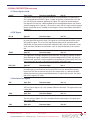
The CW25-TIM is a small size GPS OEM module that has been optimized for precision timing applications.
The CW25-TIM leverages 12,288 correlators in the BB25IC baseband processor for low signal acquisition and
tracking, eliminating the need for an outdoor antenna in many applications. Aside from low signal tracking, the
CW25-TIM’s algorithms also support quick Time To First Fix (TTFF) in cold start conditions or when ephemeris
and almanac data is available. To optimize timing performance, CW25-TIM fixes its position after initially acquiring satellites and performing a survey. When the position is fixed, even in severely degraded signal conditions
the CW25-TIM can continue to provide a time solution with only one available satellite.
With a size of just over an inch square (25 x 27 mm) and provided as a tape and reel component, the CW25TIM is specifically designed to be integrated with Communications devices such as GSM, CDMA, UMTS modems or any other communications medium. The CW25-TIM is optimized for the output of time/ frequency
information. Another aid to integration is the ability to store users’ software code in the CW25-TIM, reducing the
need for external memory and processors.
Key Features of the CW25-TIM include:
• 25 ns accuracy to UTC
• Enables indoor use
-155 dBm acquisition with network assist
-156 dBm tracking
-143 dBm acquisition stand alone
• Rapid Time To Fix
<2 second outdoors
<5 second indoors (-148dBm)
• Stand-alone CW25-TIM module
No GPS knowledge required for hardware integration
• 25 mm x 27 mm x 4.2 mm
This document, the CW25-TIM Data Sheet, provides information on the Hardware and Software Elements
of the CW25-TIM.
Key information includes:
• System Block Diagram
• Maximum Ratings
• Physical Characteristics
CW25-TIM Dimensions, castellation information
Solder Pad and placement information
• Signal Descriptions
• Special Features
• Application Information
Power supply modes
RF connections
Grounding
Battery Back-up
Over Voltage and Reverse Polarity
LED’s
The specifications in the following sections refer to the standard software builds of the CW25-TIM. The performance and specification of the CW25-TIM can be modified with the use of customized software builds.
NS18-DSCW25-TIM
Rev 07
Copyright ©2009 NavSync Ltd. All Rights Reserved
Date: 03/26/09
Specifications subject to change without notice.
2 SPECIFICATION 1
2.1 Performance
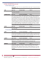
Physical
Module dimensions
Supply voltages
Operating Temp
Storage Temp
Humidity
Max Acceleration / Jerk
25mm (D) x 27mm (W) x 4.2mm (H)
3V3 (Digital I/O), 3V3 (RF), 1V8 (Core option), 3V (Standby Battery)
-30°C to +80°C
-40°C to +85°C 2
5% to 95% non-condensing
4g / 1gs-1 (sustained for less than 5 seconds)
Sensitivity
Acquisition w/network assist
Tracking
Acquisition Stand Alone
-155dBm
-156dBm
-143dBm
Acquisition
Time
Hot Start with network assist
Stand Alone (Outdoor)
Outdoor: <2s
Indoor (-148dBm): <5s
Cold: <45s
Warm: <38s Hot: <5s
Reacquisition: <0.5s (90% confidence)
Accuracy Position: Outdoor / Indoor
Velocity
Latency
Raw Measurement Accuracy
Tracking
<5m rms / <50m rms
<0.05ms-1
<200ms
Pseudorange <0.3m rms, Carrier phase <5mm rms
Code and carrier coherent
Power
1 fix per second
Coma Mode Current
(RF3V3+DIG 3V3)
Standby Current (VBATT)
0.6W typically
10mA
Interfaces
Serial
Multi-function I/O
Protocols
binary message formats
1pps Timing Output
Event Input
Frequency Output (GPIO [0])
Receiver Type
3 UART ports, CMOS levels
1PPS and Frequency Output available on GPIO [0]
Event Counter/Timer Input
Up to 4 x GPIO (multi-function)
2 x LED Status Drive
I2C, External Clock (on special build)
Network Assist, NMEA 0183, Proprietary ASCII and Processor
ARM 966E-S on a 0.18µ process at up to 120 MHz.
General
1.5µA
30ns rms accuracy, <5ns resolution
User selectable pulse width
30ns rms accuracy, <10ns resolution
10 Hz to 30 MHz (CW25-TIM)
12 parallel channel x 32 taps up to 32 point FFT.
Channels, taps and FFT can be switched off to minimize power or simulate simpler designs.
Note: 1. The features listed above may require specific software builds and may not all be available in the initial release.
2. Please contact factory for other temperature options.
Table 3 CW25-TIM Specification
NS18-DSCW25-TIM
Copyright ©2009 NavSync Ltd. All Rights Reserved
Rev 07
Date: 03/26/09
Specifications subject to change without notice.
2 SPECIFICATION continued
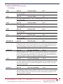
2.2 Recommended Ratings
Symbol
Parameter
Min
Max
Units
RF_3V3
RF Supply Voltage
+3.0
+3.6
Volts
DIG_3V3
Digital Supply Voltage
+3.0
+3.6
Volts
DIG_1V8
Digital Supply Voltage
+1.65
+1.95
Volts
VBATT
Battery Backup Voltage
+2.7
+3.5
Volts
ANT_SUPPLY
Antenna Supply Voltage
+3.0
+12
Volts
Table 4 Recommended Maximum Ratings
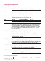
2.3 Absolute Maximum Ratings
Symbol
Parameter
Min
Max
Units
RF_3V3
RF Supply Voltage
-0.3
+6.5
Volts
DIG_1V8
Digital Supply Voltage
-0.3
+2.0
Volts
DIG_3V3
Digital Supply Voltage
-0.3
+3.7
Volts
VBATT
Battery Backup Voltage
-0.5
+7.0
Volts
ANT_SUPPLY
Antenna Supply Voltage
-15
+15
Volts
DIG_SIG_IN
Any Digital Input Signal -0.3
+5.5
Volts
RF_IN
RF Input
-15
+15
Volts
TSTORE
Storage temperature
-40
+85
°C
IOUT
Digital Signal Output Current -6
+6
mA
Table 5 Absolute Maximum Ratings
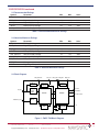
2.4 Block Diagram
ANT_SUPPLY
RF Block
RF_IN
TRIM/EXT_CLK
RF_3V3
DIG_1V8/+1V8_OUT
Regulator
& Reset
DIG_3V3
Regulator
Control
Front
End
Filter
Emulation
RF25IC
BB25IC
Comms & I/O
Clock
IF
Filter
RTC &
EEPROM
NPOR
2
IC
VBATT
Figure 1 CW25-TIM Block Diagram
NS18-DSCW25-TIM
Rev 07
Copyright ©2009 NavSync Ltd. All Rights Reserved
Date: 03/26/09
Specifications subject to change without notice.
3 PHYSICAL CHARACTERISTICS
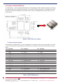
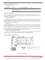
The CW25-TIM is a multi-chip module (MCM) built on an FR4 fiberglass PCB. All digital and power connections
to the CW25-TIM are via castellations on the 25 x 27 mm PCB. The RF connection is via castellations or an RF
connector. The general arrangement of the CW25-TIM is shown in the diagram below. Dimensions are in mm
(inches/1000).
.
O: . - HIROSE
H.FL CONNECTOR
PART NO: H.FL-R-SMT
Actual Size
Figure 2 CW25-TIM Form and Size
3.1 Physical Interface Details
The interface to the CW25-TIM is via 1mm castellations on a 2mm pitch. There are 42 connections in all. There
is also an RF connector for connecting to the GPS antenna. The details of the interface connections are given
below.
Pin Function
Pin Function
Pin Function
1
TX[0]
15 NTRST
29 N2WDA
2
RX[0]
16 NPOR
30 USBP
3
TX[2]
17 RFV_OUT
31 USBN
4
RX[2]/EV2_IN
18 RF_GND
32 FREQ_OUT
5
TX[1]
19 RF_3V3
33 +1V8_OUT
6
RX[1]
20 TCK
34 DIG_1V8
7
EXT_CLK 21 JTAGSEL/RTCK
35 DIG_GND
8
LED_RED
22 TMS
36 DIG_3V3
9
LED_GRN
23 RF_GND
37 EVENT_IN
10 NRESET
24 RF_IN
38 1PPS
11 BOOTSEL
25 RF_GND 39 GPIO[0]/PWM_OUT 3
12 TRIM
26 ANT_SUPPLY
40 GPIO[1]/TIME_SYNC
13 TDO
27 VBATT
41 GPIO[2]/NEXT_INT
14 TDI
28 N2WCK
42 GPIO[3]/FREQ_IN
Note: 3. Frequency Output is available on pin 32 (FREQ_OUT) with custom software only.
Table 6 CW25-TIM Signal List
NS18-DSCW25-TIM
Copyright ©2009 NavSync Ltd. All Rights Reserved
Rev 07
Date: 03/26/09
Specifications subject to change without notice.
3 PHYSICAL CHARACTERISTICS continued
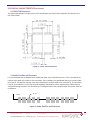
3.2 CW25-TIM Dimensions
The figure below provides the dimensions of the positioning of the CW25-TIM castellations. Dimensions are in
mm (inches/1000).
Figure 3 CW25-TIM Dimensions
3.3 Solder Pad Size and Placement
It is recommended that the footprint of the solder pad under each castellation be 2mm x 1mm, centered on the
nominal centre point of the radius of the castellation. The castellations are gold plated and so are lead free. Note
that if the RF_IN connector is being used, there should not be a pad or solder resist under the RF_IN castellation.
If the RF_IN castellation is to be used, the pad should be shortened by 0.5mm underneath the CW25-TIM and
standard RF design practices must be observed. The diagram below shows the placement of the pads under the
castellations.
RF_IN
PIN 22
Figure 4 Solder Pad Size and Placement
NS18-DSCW25-TIM
Rev 07
Copyright ©2009 NavSync Ltd. All Rights Reserved
Date: 03/26/09
Specifications subject to change without notice.
4 SIGNAL DESCRIPTION
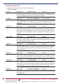
The signals on the CW25-TIM are described in the table below.
10
4.1 Power Signals
RF_3V3 Type: Power Direction: Input Pin: 19
The RF Supply Input. This 3.3V ± 10% input supplies the 2.9V LDO regulator in the
RF section of the CW25-TIM. It is important that this supply is well filtered with no
more that 50mV peak to peak noise with respect to RF_GND.
RF_GND
Type: Power
Direction: Input/Output
Pins: 18, 23, 25
The RF Input Ground. This is the return path for the RF_3V3 supply and the ground
for the antenna feed. The RF_GND must be tied to the DIG_GND externally to the
CW25-TIM.
RFV_OUT
Type: Power
Direction: Output
Pin: 17
The output from the LDO regulator that is powered by the RF_3V3 signal. This supplies the power to the RF subsystem of the CW25-TIM. This may also be used to
power external RF components but care must be taken not to inject noise onto this
signal. No more than an additional 30mA may be taken from this signal by external
circuitry.
ANT_SUPPLY
Type: Power
Direction: Input
Pin: 26
The Antenna Supply Voltage. This may be used to supply power to the RF_IN signal,
for use by an active antenna. The maximum voltage should not exceed ±15V and
the current should be limited to 50mA.
DIG_3V3
Type: Power
Direction: Input
Pin: 36
The Digital Supply Input. This 3.3V ± 10% input supplies the I/O ring of the BB25IC
chip and the LDO regulator in the digital section of the CW25-TIM. It is important
that this supply is well filtered with no more that 50mV peak to peak noise with respect to DIG_GND.
DIG_1V8
Type: Power
Direction: Input
Pin: 34
The 1.8V ± 5% digital core supply for the BB25IC. This is normally connected directly to the +1V8_OUT signal. However, if an external 1.8V ± 5% is available, a lower
overall system power consumption may be achieved by using an external supply.
+1V8_OUT
Type: Power
Direction: Output
Pin: 33
The 1.8V output from the LDO regulator that is powered by the DIG_3V3 signal.
Normally, this is connected to the DIG_1V8 signal. This may also be used to power
external logic but care must be taken not to inject noise onto this signal. No more
than an additional 50mA may be taken from this signal by external logic.
DIG_GND
Type: Power
Direction: Input/Output
Pin: 35
The Digital Ground. This is the return path for the DIG_3V3 supply and the ground
reference for all the digital I/O. The DIG_GND must be tied to the RF_GND externally
to the CW25-TIM.
NS18-DSCW25-TIM
Copyright ©2009 NavSync Ltd. All Rights Reserved
Rev 07
Date: 03/26/09
Specifications subject to change without notice.
4 SIGNAL DESCRIPTION continued
4.1 Power Signals cont’d
VBATT
Type: Power
Direction: Input/Output
Pin: 27
The Battery Backup Supply. The CW25-TIM has an on board Real Time Clock (RTC).
This is powered from the VBATT signal. A supply of typically 3v (greater than 2.5V and
less than DIG_3V3) should be applied to this signal. This signal can be left floating if
not required. The input has a blocking diode and so rechargeable batteries will need an
external charging circuit. Typically, a 1K resister in series with this signal and the external
battery will provide an easy method of measuring the current consumption from VBATT
during test.
4.2 RF Signals
RF_IN
Type: RF
Direction: Input
Pin: 24
The RF Input Signal. This attaches to the GPS antenna. Standard RF design rules must
be used when tracking to this signal. This signal has an RF blocked connection to the
ANT_SUPPLY signal. This is the same signal presented on the RF connector on the
CW25-TIM. Only one antenna connection should be made. If the RF connector is to be
used, then there should be no connection, even an unconnected pad, to this castellation.
TRIM
Type: RF
Direction: Input
Pin: 12
This signal trims the output frequency of the VCTCXO. This signal is normally left open.
When floating, this signal is biased to the control voltage of the VCTCXO. Any noise injected into this signal will severely compromise the performance of the CW25-TIM. This
signal should only be used in conjunction with specific application notes.
EXT_CLK
Type: RF
Direction: Input
Pin: 7
This input is the external clock input. This signal is to be used only in special builds of
the CW25 that are not fitted with an internal VCTCXO. For the normal build, containing the VCTCXO, do not connect this input. The external clock is a 9 MHz to 26 MHz
clipped sinewave input with an amplitude between 1V and 3V peak to peak. The return
path for this signal is RF_GND.
4.3 Emulation/Test Signals
TDI
Type: Test
Direction: Input
Pin: 14
The Test Data In Signal. This is the standard JTAG test data input. The signal return path
is DIG_GND.
TDO
Type: Test
Direction: Output
Pin: 13
The Test Data Out Signal. This is the standard JTAG test data output. The signal return
path is DIG_GND.
TCK
NS18-DSCW25-TIM
Type: Test
Rev 07
Copyright ©2009 NavSync Ltd. All Rights Reserved
Direction: Input
Date: 03/26/09
Specifications subject to change without notice.
Pin: 20
11
4 SIGNAL DESCRIPTION continued
4.3 Power Signals cont’d
The Test Clock Signal. This is the standard JTAG test clock input. The signal return path
is DIG_GND.
TMS
Type: Test
Direction: Input
Pin: 22
The Test Mode Select Signal. This is the standard JTAG test mode input. The signal
return path is DIG_GND.
JTAGSEL/RTCK
Type: Test
Direction: Input/Output
Pin: 21
This is a Dual Function Signal. When the NPOR signal is asserted (low), this signal is an
input and selects the function of the JTAG interface. When high, JTAG emulation into
the embedded ARM9 processor is selected. When low, the BB25IC chip boundary scan
mode is selected. The value on this signal is latched when NPOR de-asserts (goes high).
When NPOR is de-asserted (high) and the JTAG emulation mode has been latched, this
signal provides the return clock to the ARM Multi-ICE. Because the ARM9 functions off
a single clock domain, the TCK has to be internally synchronized in the ARM9. This can
cause a variable length delay in the validity of the TDO signal. The RTCK is a synchronized version of the TCK signal. The Multi-ICE uses the RTCK output signal to indicate
when the TDO signal is valid. The signal return path is DIG_GND.
NTRST
Type: Test
Direction: Input
Pin: 15
The Test Reset Signal. This is the active low JTAG test reset signal. The signal return
path is DIG_GND.
12
4.4 Control Signals
NPOR
Type: Control
Direction: Input/Output
Pin: 16
The Power On Reset Signal. This active low, open collector signal is the master reset for
the CW25-TIM. The CW25-TIM can be held in reset by asserting this signal. The signal
can be used to reset external circuitry, but care must be taken to ensure no DC current is
drawn from this signal as the internal pull-up resistor value is 100K.
NRESET
Type: Control
Direction: Input/Output
Pin: 10
The System Reset Signal. This active low, open collector signal is generated by the
BB25IC chip in response to the assertion of the NPOR. It may also be driven to reset the
ARM9 processor in the BB25IC without completely re-initializing the chip.
BOOTSEL
Type: Control
Direction: Input
Pin: 11
The Boot Select Signal. The BB25IC has four boot up modes, but only two are supported by the CW25-TIM. This signal is sampled when the NPOR is de-asserted. If
the BOOTSEL signal is high or left floating, then the CW25-TIM boots from its on-chip
FLASH memory. If the BOOTSEL signal is pulled low, the CW25-TIM boots from its onchip ROM.
NS18-DSCW25-TIM
Copyright ©2009 NavSync Ltd. All Rights Reserved
Rev 07
Date: 03/26/09
Specifications subject to change without notice.
4 SIGNAL DESCRIPTION continued
4.5 I/O Signals
TX[0]
Type: I/O
Direction: Output
Pin: 1
The Transmit Signal for UART 0. This is a standard UART output signal. The signal return
path is DIG_GND.
TX[1]
Type: I/O
Direction: Output
Pin: 5
The Transmit Signal for UART 1. This is a standard UART output signal. The signal return
path is DIG_GND.
TX[2]
Type: I/O
Direction: Output
Pin: 3
The Transmit Signal for UART 2. This is a standard UART output signal. The signal return
path is DIG_GND.
RX[0]
Type: I/O
Direction: Input
Pin: 2
The Receive Signal for UART 0. This is a standard UART input signal. The signal return
path is DIG_GND.
RX[1]
Type: I/O
Direction: Input
Pin: 6
The Receive Signal for UART 1. This is a standard UART input signal. The signal return
path is DIG_GND.
RX[2]/EV2_IN
Type: I/O
Direction: Input
Pin: 4
This is a Dual Mode Signal. Normally, this is the receive signal for UART 2, a standard
UART receive signal. Under software control, it can also be used as general purpose I/O
or to detect events. It can be used to detect the timing of the leading edge of the start
bit of the incoming data stream. The signal return path is DIG_GND.
FREQ_OUT
Type: I/O
Direction: Input/Output
Pin: 32
Optional Frequency Output Signal. This is NOT the same signal as pin 39. This signal is
turned off by default. This is a complex signal which under software can provide any of
either an NCO generated output frequency, a PWM signal, a GPS aligned EPOCH pulse
or general purpose I/O signal. The signal return path is DIG_GND.
1PPS
Type: I/O
Direction: Input/Output
Pin: 38
The 1 Pulse Per Second Signal. This is normally a 1 pulse aligned with GPS time, but
can under software control also provide general purpose I/O or an additional event input.
The pulse width of the 1PPS is software selectable with a default of 100µs. The signal
return path is DIG_GND.
EVENT_IN
Type: I/O
Direction: Input/Output
Pin: 37
The Event Input Signal. This is normally an event timer or counter. Events are timed
against GPS time. Under software control, this input can be used as an external 48 MHz
input for the USB interface or this input can also be used for general purpose I/O. The
signal return path is DIG_GND.
NS18-DSCW25-TIM
Rev 07
Copyright ©2009 NavSync Ltd. All Rights Reserved
Date: 03/26/09
Specifications subject to change without notice.
13
4 SIGNAL DESCRIPTION continued
4.5 I/O Signals cont’d
N2WCK
Type: I/O
Direction: Input/Output
Pin: 28
The NavSync 2 Wire Clock Signal. This is the open collector I2C compatible Clock Signal for the 2 wire serial interface. The signal return path is DIG_GND.
N2WDA
Type: I/O
Direction: Input/Output
Pin: 29
The NavSync 2 Wire Data Signal. This is the open collector I2C compatible Data Signal
for the 2 wire serial interface. The signal return path is DIG_GND.
USBP 4
Type: I/O
Direction: Input/Output
Pin: 30
The positive USB Signal. The signal return path is DIG_GND.
USBN 4
Type: I/O
Direction: Input/Output
Pin: 31
The negative USB Signal. The signal return path is DIG_GND.
LED_RED
Type: I/O
Direction: Output
Pin: 8
This is a Dual Function Signal. Normally this signal is used to drive a red LED. Standard
software builds use this signal to indicate GPS status, where a Long red flash indicates
an invalid fix and Short red flashes for satellites tracked, but not used in solution. In
special software builds, this signal can be used as GPIO. This signal has a 3.3V CMOS
drive. A series limiting resistor is required to limit output current to ±5mA. The signal
return path is DIG_GND.
LED_GRN
Type: I/O
Direction: Output
Pin: 9
This is a Dual Function Signal. Normally this signal is used to drive a green LED. Standard software builds use this signal to indicate GPS status, where a Long green flash
indicates an valid 2D/3D fix and Short green flashes for number of satellites used in
solution. In special software builds, this signal can be used as GPIO. This signal has a
3.3V CMOS drive. A series limiting resistor is required to limit output current to ±5mA.
The signal return path is DIG_GND.
GPIO[0]/PWM
Type: I/O
Direction: Input/Output
Pin: 39
Normally the GPIO[0]/PWM output provides a Frequency Output that defaults to 10 MHz,
and is user configurable from 10 Hz to 30 MHz signal. The output is enabled on powerup and is steered by the GPS solution. Custom software versions can also configure this
pin for general I/O, PWM or EPOCH output. The signal return path is DIG_GND.
GPIO[1]/TIME_SYNCType: I/ODirection: Input/Output
Pin: 40
The GPIO[1]/TIME_SYNC pin provides a synchronization pulse generated by the onboard RTC. Custom software versions can also configure this pin for general purpose
I/O, or an additional PPS output. The signal return path is DIG_GND.
GPIO[2]/NEXT_INT Type: I/O
Direction: Input/Output
Pin: 41
The GPIO[2]/NEXT_INT output provides an active high status indicator for the Frequency
Output available on pin 39 (GPIO[0]/PWM). Custom software versions can also configure
this pin for general purpose I/O. The signal return path is DIG_GND.
Note: 4. USB is not supported in the current software build.
14
NS18-DSCW25-TIM
Copyright ©2009 NavSync Ltd. All Rights Reserved
Rev 07
Date: 03/26/09
Specifications subject to change without notice.
4 SIGNAL DESCRIPTION continued
4.5 I/O Signals cont’d
GPIO[3]/FREQ_IN
Type: I/O
Direction: Input/Output
Pin: 42
The GPIO[3]/FREQ_IN output provides an active high status 3D fix indicator. This indicator can also be used to determine the validity of the pin 38 (1PPS) output. The signal
return path is DIG_GND.
5 SPECIAL FEATURES
While most of the features on the CW25-TIM are just a subset of the capabilities of the CW25 and so are described in the CW25 Data Sheet and the CW25 User Manual, there are some additional features specific to the
CW25-TIM that require explanation.
5.1 User Commands
The CW25-TIM can accept a number of specific user commands for setting receiver parameters such as UART
baud rate and NMEA message subset, output frequency, etc. Many of these parameters are stored in Non-Volatile Memory (NVM) so that the settings are retained when the receiver loses power. The available commands are
defined in detail in the CW25 User Manual.
5.2 Self Survey
To optimize timing performance, the CW25-TIM performs a 10-minute survey each time the receiver is powered
up and after obtaining a GPS fix. When the survey is complete, the receiver automatically enters fixed timing
mode. For applications with specific timing performance requirements, it may be necessary to allow the survey
to complete before using the 1PPS and frequency outputs. The status of the survey can be determined by querying the receiver dynamics setting as described in the CW25 User Manual.
5.3 CW25-TIM Embedded Identification
The hardware version number is hard coded onto the CW25-TIM; firmware also contains a version number allowing for easy identification of the hardware and software version in embedded applications.
6 TAPE AND REEL SPECIFICATIONS
(I) Measured from center line of sprocket hole to center line of pocket.
(II) Cumulative tolerance of 10 sprocket holes is ± 0.20.
(III) Measured from center line of sprocket hole to center line of pocket.
(IV) Other material available.
ALL DIMENSIONS IN MILLIMETERS UNLESS OTHERWISE STATED
General Tolerance ±0.2
Drawing not to Scale
Figure 5 Tape and Reel
NS18-DSCW25-TIM
Rev 07
Copyright ©2009 NavSync Ltd. All Rights Reserved
Date: 03/26/09
Specifications subject to change without notice.
15
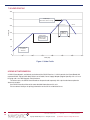
7 SOLDER PROFILE
300
Peak Temp.
245°-255°C for 15 sec Typ.
250
221°C
Temp (°C)
200
Reflow Zone
30/90 sec
(Min/Max)
150
Soaking Zone
60-90 sec Typ.
(2 min Max)
100
50
Ramp Slope not
to exceed
±3°C/sec
0
0
50
100
150
200
250
300
Time (sec)
Figure 6 Solder Profile
8 DEMO KIT INFORMATION
A CW25 Demo board is available for evaluation of the CW25 Receiver. A full kit contains the Demo Board with
mounted CW25-TIM or CW25-NAV, RS232 serial Cable, Power Supply Adaptor (Region Specific) with a 2.1 mm
DC plug and a 3m TNC Magnetic Patch Antenna. To reduce costs, the CW25 Demo Board can be purchased separately with a pick-and-choose option for
above accessories.
See CW25 Demo User Manual for more detailed information on this unit.
Please contact NavSync for pricing information on the full kit or individual items.
16
NS18-DSCW25-TIM
Copyright ©2009 NavSync Ltd. All Rights Reserved
Rev 07
Date: 03/26/09
Specifications subject to change without notice.
350
9 APPLICATION HINTS
The following are a list of application hints that may help in implementing system based on the CW25-TIM.
9.1 Power Supply
The power supply requirements of the CW25-TIM can all be provided from a single 3.3V supply. To simplify
system integration on-board regulators provide the correct voltage levels for the RF and oscillator (2.9V or 3.0V)
and low voltage digital core (1.8V). In power sensitive applications it is recommended that the DIG_1V8 supply
is provided from a high efficiency external 1.8V source e.g. switch mode power supply, rather than the on-board
linear regulator.
If the source impedance of the power supply to the CW25-TIM is high due to long tracks, filtering or other
causes, local decoupling of the supply signals may be necessary. Care should be taken to ensure that the maximum supply ripple at the pins of the CW25-TIM is 50mV peak to peak.
9.2 RF Connection
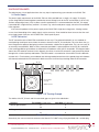
The RF connection to the CW25-TIM can be done in two ways. The preferred method is to use standard microstrip design techniques to track from the antenna element to the RF_IN castellation. This also allows the systems integrator the option of designing in external connectors suitable for the application. The user can easily fit
an externally mounted MCX, SMA or similar connector, provided it is placed adjacent to the RF_IN castellation.
If the tracking guidelines given below are followed, the impedance match will be acceptable. The diagram below
shows how this could be achieved. In this diagram, the centre via of the RF connector is presumed to be plated
through with a minimal pad top and bottom. The PCB material is assumed to be 1.6mm thick FR4 with a dielectric
constant of 4.3. Two situations are considered; one with no ground plane and one with a ground plane on the bottom
of the board, underneath the RF connector. In both cases there is no inner layer tracking under the RF connector.
RF_IN
PIN 22
Top Tracking
Ground Plane
(if used)
SMA Connector
Figure 7 RF Tracking Example
The widths of the RF_IN track and the associated gaps are given in the table below.
Scenario
Without ground plane
Track Width (1/1000 Inch)
37
56
Gap Width (1/1000 Inch)
6 8
With ground plane
32
43
6
8
Table 7 RF Track & Gap Widths
Alternatively, the user can attach the antenna to the Hirose H.FL-R-SMT using a flying lead fitted with a suitable plug.
NS18-DSCW25-TIM
Rev 07
Copyright ©2009 NavSync Ltd. All Rights Reserved
Date: 03/26/09
Specifications subject to change without notice.
17
9 APPLICATION HINTS continued
9.3 Grounding
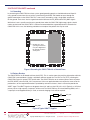
In connecting the CW25-TIM into a host system, good grounding practices should be observed. Specifically, ground currents from the rest of the system hosting the CW25-TIM should not pass through the
ground connections to the CW25-TIM. This is most easily ensured by using a single point attachment
for the ground. There must also be a good connection between the RF_GND and the DIG_GND signals.
While there is not a specific need to put a ground plane under the CW25-TIM, high energy signals should
not be tracked under the CW25-TIM. It is however recommended that a ground plane be used under the
CW25-TIM. In this case, the following would be an example of the pattern that may be used
Double via to host
system ground at this
one point. Digital and
RF grounds common
at this point.
Figure 8 Grounding the CW25-TIM with a Ground Plane
9.4 Battery Backup
The CW25-TIM has an on-board real time clock (RTC). This is used to store date and time information while the
CW25-TIM is powered down. Having a valid date and time speeds the Time To First Fix (TTFF), allowing the
CW25-TIM to meet its quoted TTFF specification. The CW25-TIM relies on an external power source to power
the RTC (VBATT) when the DIG_3V3 is not present. If the user application does not require the warm or hot fix
performance, or the required information is provided by network assistance, there is no need to provide the
VBATT signal. The VBATT signal must be greater than 2.6V and less than DIG_3V3 + 0.6V. Typically, a 3V lithium
primary cell or a high capacity “supercap” will be used. The CW25-TIM has an internal blocking diode, so if a
“supercap” or rechargeable battery is used, an external charging circuit will be required.
DIG_3V3
100R
1K
VBATT
CR2032 Cell
1K
VBATT
0.47F Supercap
DIG_GND
DIG_GND
Figure 9 Typical VBATT Supplies
18
NS18-DSCW25-TIM
Copyright ©2009 NavSync Ltd. All Rights Reserved
Rev 07
Date: 03/26/09
Specifications subject to change without notice.
9 APPLICATION HINTS continued
9.5 Over Voltage & Reverse Polarity Protection
The CW25-NAV contains no over voltage or reverse polarity protection. The CW25-NAV should be handled as
a CMOS component, with full antistatic handling precautions. Any fault condition that results in the maximum
limits being exceeded may irreparably damage the CW25-NAV.
9.6 LEDs
There are two connections on the CW25-NAV specifically intended to drive status LEDs. The LED_RED and
LED_GRN signals should be connected, via suitable current limiting resistors, to the anodes of low current LEDs
whose cathodes are connected to DIG_GND. The outputs are standard 3.3V CMOS and the current drawn
should be limited to 5mA per output. Using a 270 ohm resistor provides a suitable current limit. If appropriately
coloured LEDs are attached to these signals, other documentation (eg. user manuals) that refers to these status
LEDs will be correct. If LEDs are not required, these signals can be left open. These signals may be connected to
other logic if required.
9.7 Reset Generation
The power on reset for the CW25-NAV is generated on-board. It is generated by the regulator for the RF section.
This signal is an active low, open collector signal and is presented on the NPOR castellation. If it is desired to
extend the power on reset signal or provide a manual reset for the CW25-NAV, this signal can be driven from an
open collector source at any time. The nPOR signal of the BB25IC, to which the NPOR castellation is connected,
has a Schmitt trigger input. This means that there are no constraints on the rise time of the NPOR signal.
There is a second reset signal on the CW25-NAV, the NRESET signal. NRESET is also an active low
open collector signal. This signal is generated by the BB25IC in response to the NPOR signal. It can also be
generated under software control. Asserting the NRESET signal from an external open collector source will
reset the ARM9 in the BB25IC without resetting the whole chip. Generally, this signal will be left open.
9.8 Boot Options
The CW25-NAV has two boot modes. These are selected by the state of the BOOTSEL signal when the NPOR
signal goes inactive (high). Normally, BOOTSEL is left open so that a pull-up bias in the BB25IC will keep that
signal high. When BOOTSEL is high, the CW25-NAV boots from the FLASH that is internal to the BB25IC. If
BOOTSEL is tied low, the CW25-NAV boots from the ROM internal to the BB25IC. This ROM has a boot loader
that polls the serial ports and I2C bus for boot code. This mode of operation requires special user handling and
should only be used in conjunction with specific application notes.
9.9 Demo Board Kit Information
A CW25 Demo board is available for evaluation of the CW25 Receiver. A full kit contains the Demo Board with
mounted CW25-TIM or CW25-NAV, RS232 serial Cable, Power Supply Adaptor (Region Specific) with a 2.1 mm
DC plug and a 3m TNC Magnetic Patch Antenna. To reduce costs, the CW25 Demo Board can be purchased separately with a pick-and-choose option for
above accessories.
See CW25 Demo User Manual for more detailed information on this unit.
Please contact NavSync for pricing information on the full kit or individual items.
NS18-DSCW25-TIM
Rev 07
Copyright ©2009 NavSync Ltd. All Rights Reserved
Date: 03/26/09
Specifications subject to change without notice.
19
CW25-TIM
NavSync, Ltd. Europe
Bay 143
Shannon Industrial Estate
Shannon, Co. Clare, Ireland
Phone: +353 61 475 666
E-mail: [email protected]
North America
2111 Comprehensive Drive
Aurora, IL 60505, USA
Phone: 630.236.3026
E-mail: [email protected]
www.navsync.com