1
9 APPLICATION HINTS continued
9.5 Over Voltage & Reverse Polarity Protection
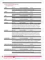
The CW25-NAV contains no over voltage or reverse polarity protection. The CW25-NAV should be handled as
a CMOS component, with full antistatic handling precautions. Any fault condition that results in the maximum
limits being exceeded may irreparably damage the CW25-NAV.
9.6 LEDs
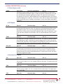
There are two connections on the CW25-NAV specifically intended to drive status LEDs. The LED_RED and
LED_GRN signals should be connected, via suitable current limiting resistors, to the anodes of low current LEDs
whose cathodes are connected to DIG_GND. The outputs are standard 3.3V CMOS and the current drawn
should be limited to 5mA per output. Using a 270 ohm resistor provides a suitable current limit. If appropriately
coloured LEDs are attached to these signals, other documentation (eg. user manuals) that refers to these status
LEDs will be correct. If LEDs are not required, these signals can be left open. These signals may be connected to
other logic if required.
9.7 Reset Generation
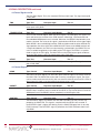
The power on reset for the CW25-NAV is generated on-board. It is generated by the regulator for the RF section.
This signal is an active low, open collector signal and is presented on the NPOR castellation. If it is desired to
extend the power on reset signal or provide a manual reset for the CW25-NAV, this signal can be driven from an
open collector source at any time. The nPOR signal of the BB25IC, to which the NPOR castellation is connected,
has a Schmitt trigger input. This means that there are no constraints on the rise time of the NPOR signal.
There is a second reset signal on the CW25-NAV, the NRESET signal. NRESET is also an active low
open collector signal. This signal is generated by the BB25IC in response to the NPOR signal. It can also be
generated under software control. Asserting the NRESET signal from an external open collector source will
reset the ARM9 in the BB25IC without resetting the whole chip. Generally, this signal will be left open.
9.8 Boot Options
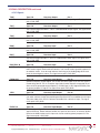
The CW25-NAV has two boot modes. These are selected by the state of the BOOTSEL signal when the NPOR
signal goes inactive (high). Normally, BOOTSEL is left open so that a pull-up bias in the BB25IC will keep that
signal high. When BOOTSEL is high, the CW25-NAV boots from the FLASH that is internal to the BB25IC. If
BOOTSEL is tied low, the CW25-NAV boots from the ROM internal to the BB25IC. This ROM has a boot loader
that polls the serial ports and I2C bus for boot code. This mode of operation requires special user handling and
should only be used in conjunction with specific application notes.
9.9 Demo Board Kit Information
A CW25 Demo board is available for evaluation of the CW25 Receiver. A full kit contains the Demo Board with
mounted CW25-TIM or CW25-NAV, RS232 serial Cable, Power Supply Adaptor (Region Specific) with a 2.1 mm
DC plug and a 3m TNC Magnetic Patch Antenna. To reduce costs, the CW25 Demo Board can be purchased separately with a pick-and-choose option for
above accessories.
See CW25 Demo User Manual for more detailed information on this unit.
Please contact NavSync for pricing information on the full kit or individual items.
NS18-DSCW25-TIM
Rev 07
Copyright ©2009 NavSync Ltd. All Rights Reserved
Date: 03/26/09
Specifications subject to change without notice.
19