1
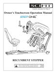
Kid Kart Xpress
User
Instruction
Manual &
Warranty
SUPPLIER:
THIS MANUAL MUST BE GIVEN TO THE
USER OR OWNER OF THIS DEPENDENT
MOBILITY BASE.
BEFORE USING THIS DEPENDENT MOBILITY
BASE READ THIS ENTIRE MANUAL AND
SAVE FOR FUTURE REFERENCE.
J With Transit Option
J Without Transit Option
I .
I N T R O D U C T I O N
SUNRISE LISTENS
Thank you for choosing this dependent mobility device.We want to hear your
questions or comments about this manual, the safety and reliability of your mobility device, and the service you receive from your Sunrise Medical supplier. Please
feel free to write or call us at the address and telephone number below:
SUNRISE MEDICAL
7477 East Dry Creek Parkway
Longmont, CO 80503
303-218-4600
800-333-4000
Be sure to return your warranty card, and let us know if you change your address.
This will allow us to keep you up to date with information about safety, new products and options to increase your use and enjoyment of this mobility device. If
you lose your warranty card, call or write and we will gladly send you a new one.
FOR ANSWERS TO YOUR QUESTIONS
Your authorized supplier knows your mobility device best and can answer most of
your questions about safety, use and maintenance. For future reference, fill in the
following:
Supplier:______________________________________________________________________________
Address: ______________________________________________________________________________
______________________________________________________________________________________
Telephone: ____________________________________________________________________________
Serial #:______________________________________ Date/Purchased: ________________________
3
9921700000 Rev D
1 1 .
TA B L E
O F
1.
11.
111.
IV.
C O N T E N T S
INTRODUCTION ..............................................................................
TABLE OF CONTENTS ..................................................................
YOUR XPRESS AND ITS PARTS ..............................................
GENERAL WARNINGS ..................................................................
A. Weight Limit ......................................................................................
B. Getting To Know Your Xpress........................................................
C. Safety Checklist..................................................................................
D. Changes & Adjustments ..................................................................
E. Environmental Conditions ..............................................................
F. Street Use ..........................................................................................
G. Motor Vehicle Safety ........................................................................
H. For Caregivers....................................................................................
V. WARNINGS FOR SAFE USE........................................................
A. Transit Use..........................................................................................
B. Center of Balance ............................................................................
C. Dressing of Changing Clothes........................................................
D. Obstacles ............................................................................................
E. Reaching or Leaning..........................................................................
F. Ramps, Slopes & Side Hills ..............................................................
G. Transfers ..............................................................................................
H. Curbs & Steps ....................................................................................
I. Climbing Stairs ..................................................................................
J. Descending Stairs ..............................................................................
K. Escalators ............................................................................................
L. Maintenance........................................................................................
VI. WARNINGS FOR COMPONENTS & OPTIONS ..............
A. Transit Option....................................................................................
B. Anti-Tip Tubes ....................................................................................
C. Tray Support ......................................................................................
D. Cushions..............................................................................................
E. Fasteners ............................................................................................
F. Footbeds..............................................................................................
G. Tires......................................................................................................
H. Positioning Belts ................................................................................
I. Power Drive ......................................................................................
J. Attendant Handle..............................................................................
K. Quick-Release Axles ........................................................................
L. Wheel Locks ......................................................................................
M. Modified Seat Systems......................................................................
N. Upholstery Fabric..............................................................................
9921700000 Rev D
4
3
4
6
8
8
8
8
9
9
9
9
10
11
11
12
12
12
12
13
13
13
14
14
14
14
15
15
16
16
16
16
16
17
17
17
17
17
17
17
17
1 1 .
TA B L E
O F
C O N T E N T S
VII. OPERATING INSTRUCTIONS....................................................
A. Wheel Locks ......................................................................................
B. Unfolding ............................................................................................
C. Folding Frame & Rotating Handle Into Storage Position ........
D. Rear Wheel Removal & Installation ..............................................
E. Transit Use..........................................................................................
F. Positioning Shell Installation............................................................
G. Positioning Shell Removal................................................................
H. Tilt-In-Space (TIS) Angle Adjustment............................................
I. Hip Angle Adjustment ......................................................................
J. Recline Adjustment ..........................................................................
K. Knee Angle Adjustment....................................................................
L. Sunshade Installation & Adjustment..............................................
M. Positioning & Growth Adjustments Guide ..................................
N. Seat Depth Adjustment....................................................................
O. Standard Seat Cushion Adjustment ..............................................
P. Contoured Seating System Cushion Adjustments ....................
Q. Standard Cushion without Lateral Hip Support........................
R. Back Positioning Plate Height Adjustment ..................................
S. Back Cushion Height Adjustment..................................................
T. Footbed Adjustments ......................................................................
U. Pelvic Positioning Belt Length Adjustment ..................................
V. Pelvic Positioning Belt Position Adjustment................................
W. Butterfly Harness ..............................................................................
X. Lateral Trunk Supports Assembly to the Seating Shell ............
Y. Lateral Trunk Support ......................................................................
Z. Whitmyer Head Supports ..............................................................
AA. Head Support Models DFSQ1, DFSQ3, DFSQ10, DFSQ30 ..
BB. Hip pads ..............................................................................................
CC.Knee Adductors ................................................................................
DD.Knee Abductor Block Adjustment ................................................
EE. Tray Support Adjustment ................................................................
FF. Tray Installation & Adjustment ......................................................
GG.Foot Strap Adjustment ....................................................................
HH.Shoe Holder Strap Adjustment ......................................................
VIII. MAINTENANCE..................................................................................
IX. LIMITED WARRANTY ....................................................................
5
18
18
18
19
21
22
24
24
25
25
25
26
26
27
27
28
28
29
30
30
30
31
31
32
33
34
35
36
38
38
39
39
39
40
40
41
42
9921700000 Rev D
1 1 1 .
Y O U R
X P R E S S
A N D
I T S
P A R T S
8
3
4
12
11
9
14
5
13
5
6
2
1
7
10
K I D
K A R T
8. Sunshade adjustment control
9. Positioning shell
10.Mobility base
11.Tilt in space block
12.Tilt in space adjustment
mechanism
13. Tray support
14.Trigger mechanism
1.
2.
3.
4.
Wheel locks
Safety Lockout Pin
Recline Control (optional)
Addentant handle adjustment
control button
5. Transit Option (optional)
securement points
6. Footbed adjustment mechanism
7. Anti-tip tubes
9921700000 Rev D
X P R E S S
6
1 1 1 .
Y O U R
X P R E S S
A N D
I T S
P A R T S
KID KART XPRESS TECHNICAL SPECIFICATIONS
Dimensions:
Overall Width: 24"
Floor-to-seat height: 21"
Folded dimensions: 24" X 28" X 20"
Seating Options
Standard Cushion without-Lateral Hip
Support
Adjustable Contour Cushion w/o
Lateral Hip Support
Weight:
34 lbs.
Shell only weight: 16 lbs.
Base only weight: 18 lbs.
Color Options
Frame:
Purple, Silver, Pink, Black
Seating Shell Fabric Colors:
Jazz, Classic, Kaki-Smoke, Red-Black
All features may not be available with some
configurations or in conjunction with another
product feature. Please consult your supplier
or customer service for more information.
Your authorized supplier can also provide
you with more information on accessories.
Seat & Back Fabric Colors:
Black (US Only), Gray, Navy
Adjustment ranges:
Tilt range: 0-45°
Recline: 85° to 130°
Handle bar height: 36.5" to 41"
Seat depth: 5.5" to 13"
Seat width (at hip): 11.5"
w/opt. lateral hip supports 6.5"-10"
Knee width: 13" w/opt. lateral knee
supports 5"-11"
Top of head to seat: 13" to 22"
Top of shoulder to seat: 7.5" to 16"
Axilla (under arm) to seat: 4.5" to 12"
Chest width: 4" to 10"
Width of head: 3.75" to 7"
Shoulder width: 5" to 11"
Lower Leg/Foot: 5" to 14"
Footbed adjustment:
70° to 170° extension
7
9921700000 Rev D
I V.
! G
L
E N E R A L
W A R N I N G S
Throughout this section, you will find general warnings for the safe use of your
dependent mobility device. It is important that you read and understand these
warnings before you use this product. If you fail to do so, a fall, tip over or loss
of control may occur and cause severe injury to the rider, you or others.
A. WEIGHT LIMIT
Never exceed the weight limit for the rider (55 lbs) or for items carried in the storage
areas (15 lbs). The combined weight limit for the rider and storage areas is 70 pounds.
Never use the mobility device for more than one rider.
B. GETTING TO KNOW YOUR XPRESS
Read all instructions before using this product. In particular, you should:
1. Be trained in the safe use of this product by your health care professional.
2. Practice bending, reaching and transfers until you know the limit of your
ability. Have someone help you until you know what can cause a fall or tip
over and how to avoid doing so.
3. Be aware that you must develop methods for safe use best suited to your
level of function and ability.
4. Never try a new maneuver on your own until you are sure you can do it
safely.
5. Get to know the areas where you plan to use your mobility device. Look
for hazards and learn how to avoid them.
6. Always use anti-tip tubes when this product is unfolded and in use.
C. SAFETY CHECKLIST
Before each use of this product:
1. Wheel locks must be adjusted to maintain proper performance. Always
engage the wheel locks before transferring a child.
2. Make sure the mobility device rolls easily and that all parts work smoothly.
Check for noise, vibration, or a change in ease of use. (They may indicate
low tire pressure, loose fasteners, or other damage).
3 Repair any problem you may encounter. Your authorized supplier can help
you find and correct any problems.
4 Check to see that both quick-release rear axles are locked. When locked,
the axle button will "pop out" fully. If not locked, the wheel may come off
and cause a fall.
5 Lock the anti-tips in place.
6. Never seat your child in the mobility device until is fully unfolded and
locked.
7. Use a pelvic positioning belt when the child is seated.
8. Never leave your child unattended.
9921700000 Rev D
8
I V.
! G
L
E N E R A L
W A R N I N G S
D. CHANGES & ADJUSTMENTS
1. See your health care professional and have them adjust components and
accessories as your child grows.
2. Unauthorized modifications or use of parts not supplied or approved by
Sunrise Medical may change the product's structure. This will void the
warranty and may cause a safety hazard.
E.
ENVIRONMENTAL CONDITIONS
1. Your mobility device is designed for use on firm, even surfaces such as
concrete, asphalt and indoor floors and carpeting.
2. Use extra care if you must use this mobility device on a wet or slick
surface. If you are in doubt, ask for help.
3. Do not use this product in a shower, pool or other bodies of water.
4. Do not operate your mobility device in sand, loose soil or over rough terrain.
F.
STREET USE
1. This product is not intended for street use.
2. Be alert to the danger of motor vehicles on roads or in parking lots.
3. At night, or when lighting is poor, use reflective tape or clothing.
4. Due to your child's low position, it may be hard for drivers to see the
rider. Make eye contact with drivers before you go forward. When in
doubt, yield until you are sure it is safe.
G. MOTOR VEHICLE SAFETY
As indicated on the front cover of this user manual, identify whether your
chair has been manufactured with the Transit Option installed.
NEVER USE THE MOBILITY DEVICE SHELL AS A CAR SEAT.
If your chair is NOT equipped with the Transit Option:
Mobility device products do not meet federal standards for motor vehicle seating.
1. NEVER let anyone sit in this product while in a moving vehicle.
2. ALWAYS move the rider to an approved vehicle seat.
3. ALWAYS secure the rider with proper motor vehicle restraints.
4. In an accident or sudden stop the rider may be thrown from the mobility
device. Mobility device pelvic positioning belts will not prevent this and
further injury may result from these belts or straps.
5. NEVER transport this mobility device in the front seat of a vehicle. It may
shift and interfere with the driver.
6. When being transported in a vehicle, ALWAYS secure the unoccupied
mobility device so that it cannot roll or shift.
7. Do not use this product if it has been involved in a motor vehicle accident.
If your chair is equipped with the Transit Option, refer to the following sections:
V. Warnings for Safe Use: A. Transit Use; VI. Warnings for Components & Options:
A. Transit Use; and VII. Operating Instructions: E. Transit Use.
9
9921700000 Rev D
I V.
! G
L
E N E R A L
W A R N I N G S
H. FOR CAREGIVERS
1. Work with the child's health care professional to learn safe methods best
suited to your abilities and those of your child.
2. To prevent injury to your back, use good posture and proper body
mechanics when lifting or tilting your child.
3. Remind the child to lean back when you tilt the mobility device backward.
4. When you descend a curb or single step, slowly lower the mobility device
in one easy movement.
5. NEVER leave the child alone.
6. When making adjustments to the mobility device, always engage the wheel
locks to help minimize unintended movement.
9921700000 Rev D
10
V.
!
L
W A R N I N G S
F O R
S A F E
U S E
A. TRANSIT USE
1. If possible and feasible, the child should be transferred to a car seat and
the vehicle restraint used.
2. If the mobility device is used for transport and has been installed
with the Transit Option, it must be used in a vehicle equipped for
forward-facing securement during transport.
3. The rider must not weigh more than 55 lbs.
4. Figures 1 & 2 show the location of the transit securement points (A) for
this product.
5. • For children over 20lbs. use only with Wheelchair Tiedown and
Occupant Restraint Systems (WTORS) that have been installed in
accordance with the manufacturer's instructions and SAE J2249.
• 5b. For children 20lbs and under. use only with Wheelchair Tiedown that
have been installed in accordance with the manufacturer's instructions
and SAE J2249. You must use the occupant restraints provided with the
Kid Kart Express.
6. Attach WTORS to securement points in accordance with the
manufacturer's instructions and SAE J2249.
7. Attach occupant restraints supplied with your product that was equipped with
the transit option in accordance with this owner’s manual and SAE J2249.
NOTE: To obtain a copy of SAE J2249 Wheelchair Tiedown and Occupant Restraint
Systems for Use in Motor Vehicles, please contact the Society of Automotive Engineers
724/776-4841 or www.sae.org/
A
A
A
A
Figure 1– rear securement points
Figure 2– front securement points
11
9921700000 Rev D
V.
!
L
W A R N I N G S
F O R
S A F E
U S E
B. CENTER OF BALANCE
Kid Kart mobility devices are designed for stability and performance. The point where
this device will tip forward, back, or to the side depends on its center of balance and
stability. The center of balance is also affected by:
•
•
•
•
•
•
The distance between the rear wheels.
The seat height and seat angle.
Backrest angle.
Changes in your child's body position, postures or weight distribution.
Pushing the mobility device on a ramp or slope.
The use of a backpack or other options, and the amount of added weight.
To maintain the proper center of gravity and balance:
• Consult your therapist and supplier when the mobility device is set up.
• Consult your authorized supplier or therapist BEFORE you modify or
adjust the mobility device.
• Use anti-tip tubes.
C. DRESSING OR CHANGING CLOTHES
Your child's weight may shift if you dress or change your child's clothes while they are
seated in the mobility device. To reduce the risk of a fall or tip over while changing
clothes or diapers:
•
•
•
Rotate the front casters until they are as far forward as possible.
Engage the wheel locks
Ensure that anti-tip tubes are in the down position.
D. OBSTACLES
Obstacles and road hazards (such as potholes and broken pavement) can damage your
mobility device and may cause a fall, tip over or loss of control. To avoid these risks:
•
•
•
E.
Scan the area well ahead for danger as you push the mobility device.
Make sure the floor areas ahead are level and free of obstacles.
Install a ramp at entry or exit doors. Make sure there is not a drop off at
the bottom of the ramp.
REACHING OR LEANING
If your child reaches or leans it will affect the center of balance of your mobility device.
This may cause a fall or tip over.
•
•
NEVER allow your child to reach or lean if they must shift their weight
sideways, forward, or backward and rise up off the seat.
If your child must reach, move the mobility device as close as you can to
the object they wish to reach and rotate the front casters until they are as
far forward as possible.
NOTE: To do this: Move your mobility device past the object you want to reach, then back
up alongside it.
9921700000 Rev D
12
V.
!
L
W A R N I N G S
F O R
S A F E
U S E
F. RAMPS, SLOPES & SIDE HILLS
Pushing the mobility device on a slope, including ramps or hills, will change the center of
balance. A few safety reminders include:
1. Do not push this product on a slope steeper than 10%. (A 10% slope
means: one foot in elevation for every ten feet of slope length.)
2. Do not turn or change direction on a slope or ramp.
3. For your child's safety, ramps at home and work must meet all legal
requirements for your area.
4. Always stay in the CENTER of the ramp.
5. Use a ramp with guardrails (or raised borders at least 3" high).
6. Always go straight up and straight down on hills or ramps.
7. Do not stop on a steep slope.
8. Watch for a drop-off at the bottom of a slope or ramp.
9. Do not engage the wheel locks to slow or stop your mobility device.
10. Beware of wet or slippery surfaces.
11. Do not recline or tilt the shell while going up hills.
12. Ask for help any time you are in doubt.
G. TRANSFERS
1. Work with your health care advisor to learn safe transfer and lifting
methods.
2. Have someone help you until you know how to do a safe transfer of your
child on your own.
3. Engage the wheel locks before you transfer. This keeps the rear wheels
from rolling.
4. Move your child's mobility device as close as you can to the seat you are
transferring to.
5. Rotate the front casters until they are as far forward as possible.
6. Transfer your child as far back onto the seat surface as you can. This will
reduce the risk that the mobility device will tip or move away from you.
H. CURBS & STEPS
Follow the instructions below for descending or climbing a stair or curb. Do not try to
climb a high curb or step (more than 4 high) unless you have help. Doing so may cause
your mobility device to exceed its balance point and tip over.
To descend a curb or single step going BACKWARD:
1. Stay at the rear of the mobility device.
2. Several feet before you reach the edge of the curb or step, turn the
mobility around and pull it backward.
3. While looking over your shoulder, carefully step back until you are off the
curb or stair and standing on the lower level.
4. Pull your mobility device toward you until the rear wheels reach the edge
of the curb or step. Then allow the rear wheels to slowly roll down onto
the lower level.
13
9921700000 Rev D
V.
!
L
W A R N I N G S
F O R
S A F E
U S E
5. When the rear wheels are safely on the lower level, tilt the mobility device
back to its balance point. This will lift the front casters off the curb or step.
6. Keep the mobility device in balance and take small steps backward. Turn
the mobility device around and gently lower front casters to the ground.
To climb a step or curb going FORWARD:
1. Stay behind the mobility device.
2. Face the curb and tilt the mobility device up on the rear wheels so that
the front casters clear the curb or step.
3. Move forward, placing the front casters on the upper level as soon as you
are sure they are past the edge.
4. Continue forward until the rear wheels contact the face of the curb or
step. Lift and roll the rear wheels to the upper level.
I.
CLIMBING STAIRS
1. Use at least two attendants to move this mobility device up stairs.
2. Move the mobility device and rider BACKWARD up the stairs.
3. The person at the rear is in control. He or she tilts the mobility device
back to its balance point.
4. A second attendant at the front firmly grasps a non-detachable part of the
front frame and lifts the mobility device up and over one stair at a time.
You may want to rotate the anti-tippers up so that they do not interfere
with steps.
5. The attendants move to the next stair up. Repeat for each stair, until you
reach the landing.
J.
DESCENDING STAIRS
1. Use at least two attendants to move an occupied mobility device down stairs.
2. Move the mobility device and rider FORWARD down the stairs.
3. The person at the rear is in control. He or she tilts the mobility device to
the balance point of the rear wheels and rolls it to the edge of the top step.
4. A second attendant stands on the third step from the top and grasps the
frame. He or she lowers the chair one step at a time by letting the rear
wheels roll over the stair edge.
5. The attendants move to the next stair down. Repeat for each stair, until
you reach the landing.
K. ESCALATORS
NEVER use this mobility device on an escalator, even with an attendant.
L.
MAINTENANCE
Proper maintenance of your mobility device will ensure a long life for the product.
Inspect and maintain this mobility device per the Maintenance details listed in the back
of this booklet. If you detect a problem, make sure to service or repair the product
before use.
9921700000 Rev D
14
V I .
! W A R N I N G S
L
F O R
C O M P O N E N T S
&
O P T I O N S
Below are warnings for various standard and optional components for your
Xpress. (Options may vary based on your Kid Kart model.) If you fail to heed
these warnings, you may cause damage to your Kid Kart, a fall, tip over or a
loss of control that may cause severe injury to the child, caregiver or others.
A. TRANSIT OPTION
1. Use only Wheelchair Tiedown and Occupant Restraint Systems (WTORS)
which meet the requirements of SAE J2249 Recommended Practice Wheelchair Tiedown and Occupant Restraint Systems for Use in Motor
Vehicles. Do not use WTORS designed to rely on the stroller structure to
transfer occupant restraint loads to the vehicle.
2. Attach occupant restraints supplied with your product that was equipped with
the transit option in accordance with this owner’s manual and SAE J2249.
3. • For children over 20lbs the positioning shell/mobility base unit has been
dynamically tested with the occupant facing forward for a 30 mph (48-km/h)
frontal impact test. The occupant must be facing the front of the vehicle
during transport. See Figure A.
• For children 20lbs and under the positioning shell/mobility base unit has
been dynamically tested with the occupant facing rearward for a 30 mph
(48-km/h) frontal impact test. The occupant must be facing the rear of the
vehicle during transport. See Figure B.
Figure A_Forward Facing
Figure B_Reversed Facing
Front of Vehicle
Front of Vehicle
15
9921700000 Rev D
! W A R N I N G S
V I .L
F O R
C O M P O N E N T S
&
O P T I O N S
4. Postural supports and positioning
devices should not be relied on for
occupant restraint, other than the
occupant restraint system provided with
the system. See Figure C.
5. To reduce the potential of injury to
vehicle occupants, mobility device
mounted accessories, such as trays
and respiratory equipment, should be
removed, and secured separately. The
optional Kid Kart Xpress vent tray,
Figure C_Occupant Restraint
oxygen holder, and IV pole must also
be removed and secured separately
before using as a seat in a motor vehicle.
6. Do not alter or substitute mobility device frame parts, components or seating.
7. Sudden stops or impacts may structurally damage your stroller. Mobility
devices involved in such incidents should be replaced.
B. ANTI-TIP TUBES
Anti-tip tubes can help keep your mobility device from tipping. Do not remove
the anti-tip tubes and use in down position whenever the base is unfolded.
C. TRAY SUPPORTS
1. Do not lift this product by its tray supports.
2. Do not rest drinks on tray supports.
D. CUSHIONS
This mobility device's seating was designed for comfort and postural support. If
seating component modifications are necessary, consult your therapist or clinician.
E.
FASTENERS
Many of the screws, screws and nuts on this product are special high-strength
fasteners. ONLY use fasteners provided by an authorized supplier (or ones of
the same type and strength, as indicated by the markings on the heads), do not
over- or under-tightened fasteners, and If screws or screws become loose,
tighten them as soon as you can.
F.
FOOTBEDS
1. At the lowest point, footbeds should be at least 2" off the ground. If set too
low, footrest may interfere with obstacles you may encounter during
normal use.
2. Adjustment of the footbed may cause interference with the casters in
some positions. This may affect your ability to stear the Kart.
3. Avoid putting weight on the footbed. The mobility device may tip forward
(or backward if shell has been reversed).
4. Never lift this mobility device by the footbeds.
9921700000 Rev D
16
! W A R N I N G S
V I .L
F O R
C O M P O N E N T S
&
O P T I O N S
G. TIRES
Proper inflation extends the life of your tires and makes your mobility device
easier to use. Do not under- or over-inflate tires. Check weekly for proper
inflation level, as listed on the tire side wall.
H. POSITIONING BELTS
Use positioning belts ONLY to help support the child's posture.
1. Make sure the rider does not slide down in the mobility device seat. The belts
must be snug, but must not be so tight that they interfere with breathing.You
should be able to slide your open hand, flat, between the belt and the rider.
2. Use positioning belts with a cooperative rider only. Make sure that you can
remove the belts in an emergency.
3. NEVER Use Positioning Belts:
• As a restraint.
• On a child who is comatose, agitated or is prone to seizures.
• As a motor vehicle restraint– except those that are included with the
transit option for the purpose of occupant restraint.
I.
POWER DRIVE
Do not install a power drive on this product.
J.
ATTENDANT HANDLE
Your mobility device's attendant handle provides secure points for a caregiver
to grasp the rear of this Kart, to prevent a fall or tip over. Check to make sure
handle is locked in place after adjusting height.
K. QUICK-RELEASE AXLES
If this product has quick-release axles, ensure that both quick-release rear
axles are locked before using this product. An axle is not locked until the
quick-release button pops out fully. Quick-release axles should be inspected
for function and any signs of wear or bending.
L.
WHEEL LOCKS
Never engage wheel locks to slow or stop this product when it is moving. To
keep the rear wheels from rolling, always engage both rear wheel locks when
you transfer your child to or from this mobility device. Make sure lock arms
embed in tires at least 1/8" when locked.
M. MODIFIED SEATING SYSTEMS
Do not change the seating system of your Kart UNLESS you consult your
health care professional.
N. UPHOLSTERY FABRIC
Replace worn or torn seating cover fabrics as soon as you can, and be aware
that laundering or excess moisture will reduce flame retardation of the fabric.
17
9921700000 Rev D
V I I .
O P E R AT I N G
I N S T R U C T I O N S
A. WHEEL LOCKS
1. Loosen bolts and adjust wheel lock contact bar downwards. Lock arms
should embed into tires minimum of 1/8th inch when locked.
2. With the wheel locks on the rear wheels should skid, not roll when the Kid
Kart is pushed with a child in the product.
Wheel lock
adjusment
bolts
Wheel Lock Adjustment
Figure 1 (unlocked)
Figure 2 (locked)
B. UNFOLDING
1. Unhook fold retaining strap and store in tray provided under seating shell.
2. Insert or rotate anti-tippers into a downward position facing the ground.
(See Fig. 3)
3. Place the mobility base on the floor with wheel locks engaged. Make sure
that the mobility base fold lock out pin is not inserted into the lock out
hole. (See Fig. 3)
4. Lift the handle bar over into locked position, then lift up so that the frame
unfolds and locks into an upright position. (See Fig. 4 and 5)
5. Insert the mobility base lock pin into the lockout hole. When inserted into
the hole, the lock pin prevents the rear wheels and axle from folding under
the Kart.
Before seating a child always check that the mobility base is properly
locked in its upright position, that the fold lockout pin is inserted, and
that the wheel locks are engaged.
Figure 4
Figure 3
9921700000 Rev D
18
V I I .
O P E R AT I N G
I N S T R U C T I O N S
Figure 5
Figure 6
6. If the shell is being installed separately, see positioning shell installation
instructions (Section VII-F). To position the shell back, depress the recline
lever and pull back. Adjust legrest, tilt and optional recline to appropriate
configuration. (See Fig. 6)
C. FOLDING FRAME AND ROTATING HANDLE INTO
STORAGE POSITION
Your Kid Kart is equipped with two stage folding
1. Stage one (See Fig. 8) does not effect the stroller wheels and base allowing
only the handle to be brought forward to a storage position. This is useful
for transporting the Kid Kart in the back of a vehicle.
2. Stage two (See Fig.7) allows complete folding of the Kid Kart handle and
base. This folding system is accomplished via the two stage trigger.
Figure 7
Note: Seating system removed for clarity.
Figure 8
19
9921700000 Rev D
V I I .
O P E R AT I N G
I N S T R U C T I O N S
TWO STAGE FOLDING TRIGGER
The release trigger works in two stages. (See Fig. 9 & 10) Stage one allows
the handle to fold forward (See Fig. 9) only for more compact storage.
Stage two allows the entire frame to collapse and fold (See Fig. 10).
Figure 9
Figure 10
HANDLE ONLY FOLDING (FIG. 9)
1. Remove the child from the seating system
2. Handle storage will work with or without the shell in the Kid Kart.
3. Engage the wheel locks
4. Activate the trigger handle as shown. (See Fig. 9)
9921700000 Rev D
20
V I I .
O P E R AT I N G
FOLDING FRAME COMPLETE
The mobility system folds compactly with
the shell installed. The system is designed
to fold with the seat shell installed in the
forward facing position.
1. Engage wheel locks. Remove the
child from the seat shell.
2. Elevate legrests, tilt seat to most
forward position and fold the back
forward. (See Section VII-C)
3. Pull the fold lockout pin out. (See
Fig. 11)
I N S T R U C T I O N S
Figure 11
D. REAR WHEEL REMOVAL AND INSTALLATION
The rear wheels may be removed to
reduce the mobility base storage size.
1. To remove, depress the axle release
button in the center of the rear
wheel and pull the whole wheel and
axle out of the axle tube.
(See Fig. 12)
2. To reinstall, align the axle with the
axle tube end and depress the
button to reinstall. Push axle and
wheel assembly inward until it can
go no further. When the wheel is
properly installed and the axle
release button will pop out.
Figure 12
Pull on the wheel assembly to verify that it is locked in place.
Occasionally, the wheels do not both snap into place. If this should
happen, then swap the wheels to opposite sides.
21
9921700000 Rev D
V I I .
E.
O P E R AT I N G
I N S T R U C T I O N S
TRANSIT USE
1. If possible and feasible, the rider should transfer to the vehicle seat and
use the vehicle restraints.
2. • For children over 20lbs; the occupant must be facing the front of the
vehicle during transport. See Figure A. A Wheelchair Tiedown and
Occupant Restraint Systems (WTORS) that has been tested in
accordance with SAE J2249 must be used.
• For children 20lbs and under; the
occupant must be facing the rear of
the vehicle during transport. See
Figure B. A Wheelchair Tiedown
that has been tested in accordance
with SAE J2249 must be used.
The Occupant restraint straps
provide with the Xpress must also
be used. (See Figure C)
Figure C_Occupant Restraint
9921700000 Rev D
Figure A_Forward Facing
Figure B_Reversed Facing
Front of Vehicle
Front of Vehicle
22
V I I .
O P E R AT I N G
I N S T R U C T I O N S
3. Mobility device mounted accessories,
such as trays and respiratory
equipment, should be removed, and
secured separately. The optional Kid
Kart Xpress vent tray, oxygen holder,
and IV pole must also be removed and
secured separately before using as a
seat in a motor vehicle.
4. The occupant must not weigh more
than 55 pounds.
5. The location of the securement points
is shown. (See Fig. 13, A)
7. Use only with WTORS that have been
installed in accordance with the
manufacturer's instructions and SAE
J2249.
8. Attach WTORS to the securement
points in accordance with the
manufacture's instructions and SAE
J2249.
9. Attach occupant restraints in
accordance with the manufacturer's
instructions and SAE J2249.
Note: To obtain a copy of SAE J2249
Wheelchair Tiedown and Occupant
Restraint Systems for Use in Motor
Vehicles, please contact: SAE
International on the internet at
www.sae.org/ or by phone at 724/7764841.
23
A
A
Figure 13
9921700000 Rev D
V I I .
F.
O P E R AT I N G
I N S T R U C T I O N S
POSITIONING SHELL INSTALLATION
The positioning shell has a pivot post on each side that mounts the shell to
the mobility base. The mobility base has a slot on each side that receives the
shell pivot posts. The shell will not install onto, nor remove from, the mobility
base when the mobility base push handle is folded. The positioning shell may
be installed in a child facing forward or rearward position. Installation is the
same either direction.
Reversed Position
Forward Position
Unfold the mobility base and be sure that the wheel locks are engaged.
1. Place the shell over the top of the mobility base, and squeeze the tilt-inspace (TIS) lever attached to the right side of the shell handle. (See Fig.14)
2. Align the tilt-in-space guide pins and pivot posts with the mobility base
pivot slots and lower the shell into place.
3. Adjust legrest, tilt and optional recline to appropriate configuration.
G. POSITIONING SHELL REMOVAL
1. Engage wheel locks. Remove child from
Kart. The push handle must be in its normal
use position to remove the shell.
2. Squeeze and hold the TIS lever. (See Fig.14)
3. Lift the shell vertically from the mobility
base.
Pivot
Slot
Pivot
Post
Figure 14
9921700000 Rev D
24
Guide
Pin
V I I .
O P E R AT I N G
I N S T R U C T I O N S
H. TILT-IN-SPACE (TIS) ANGLE
ADJUSTMENT
1. Engage wheel locks and move
behind the child.
2. Support the shell with both hands
and squeeze the TIS lever. It is on
the right side of the shell handle.
(See Fig. 15)
3. Orient the seating system in an
appropriate position while watching
the child.
Caution, be careful to avoid pulling or
crimping any life support tubing that
may be attached to the child.
Figure 15
4. Release the TIS lever and move shell slightly to be sure that it locks
into position.
I.
HIP ANGLE ADJUSTMENT (for Karts without recline)
1. Adjust the fixed hip angle by removing the screw that attaches the tube at
the shell back bracket. Position the shell back to desired angle and reattach the screw.
2. The lower mounting point is provided with a quick release pin to facilitate
folding of the shell back.
J.
RECLINE ADJUSTMENT (OPTIONAL)
1. Engage wheel locks and move to
the child's left side.
2. Squeeze the recline adjustment
lever. It is attached to the left side
of the shell handle. (See Fig. 16)
3. Move the back to an appropriate
position while watching the child.
Take care to avoid pulling or
crimping any life support tubing that
may be attached to the child.
4. Release the adjustment lever to
lock recline.
Figure 16
Note: One or more adjustment
limiting collars may be attached to the seating system to reduce the range
of available hip angles. They attach to the mechanical lock shaft. Consult
your supplier and therapist for adjustment needs.
25
9921700000 Rev D
V I I .
O P E R AT I N G
K. KNEE ANGLE ADJUSTMENT
1. Engage wheel locks.
2. Press down on thumb activated
levers at each side of the footbed
hanger. Levers will not move easily
until you have adequately supported
the weight of the occupant's legs.
(See Fig. 17)
3. Hold the levers and adjust knee
angle.
4. Release the levers and allow the
knee angle to lock into place as
manual leg support is gently
reduced.
I N S T R U C T I O N S
Figure 17
L. SUNSHADE INSTALLATION AND ADJUSTMENT
Sunshade Installation
1. Loosen two thumbscrews located near the top of the back. They screw
into black couplers on each side of the back.
2. Put the sunshade rod ends into the mounting holes, raise to or lower the
sunshade to proper height, and tighten the thumbscrews.
Sunshade Adjustment
1. Once installed, adjust sunshade angle by pushing it forward or backward
until desired position is obtained. (See Fig. 18)
2. Lift the front of the sunshade all the way up to swing it out of the way.
(See Fig. 19)
Figure 18
9921700000 Rev D
Figure 19
26
V I I .
O P E R AT I N G
I N S T R U C T I O N S
M. POSITIONING AND GROWTH ADJUSTMENTS GUIDE
If necessary, a healthcare professional should make any changes to
the positioning and growth adjustments. These adjustments are very
important to the orthopedic and neurological needs of the child.
Care should be taken to make sure they are appropriate.
Use the 5/32" hex head tool provided or an electric screwdriver with a 5/32" hex
head bit to adjust the seating and positioning system. The enclosed hand held hex
bit wrench is ergonomically designed to work at many angles. An electric screwdriver with a 5/32" hex head bit is useful when doing several fittings. However,
care must be taken to not over-loosen or over-tighten the screws.
In general, positioning and growth adjustments should be done in the following order:
1. Adjust seat
2. Adjust back
3. Adjust pelvic positioning belt
4. Adjust footbed
5. Adjust head support
6. Make other standard and optional adjustments needed
7. Check to be sure that all adjustment screws are tight
N. SEAT DEPTH ADJUSTMENT
1. Determine the proper seat cushion
depth.
2. Remove the seat cushion. It is
attached with Velcro®.
3. Loosen the seat depth adjustment
screws found on each side of the
frame from under the seat base.
4. Once they are loose, grasp the bar
under the front edge of the seat
and slide to the desired length.
5. Re-tighten all four adjustment
screws once the desired position is
achieved. (See Fig. 20)
27
Figure 20
9921700000 Rev D
V I I .
O P E R AT I N G
I N S T R U C T I O N S
O. STANDARD SEAT CUSHION ADJUSTMENT
The standard seat cushion comes in two seat lengths, short and long. The
short seat is 7" long with capability for adding a 2" growth strip at the back
of the cushion. The long seat is 9" long with capability for adding a 2"
growth strip at the back of the cushion. Both are capable of adjustment
from 5.5 to 11.5 inches width adjustment by adding or removing adductor
foam pads.
To adjust width:
1. Unzip and remove seat cover.
Add or remove the same
combination of adductor foam
pads to each side of the seat, to
achieve the desired width.
2. Re-install the cover over the
seat and close the zipper.
To add growth strip:
1. Unzip seat cover to expose the
back edge of the foam cushion.
2. Lift the foam overlay pad at the
back of the seat and install the
growth strip with tapered ends
down.
3. Place the overlay evenly over the
growth strip and close the zipper
around the growth strip.
P.
Standard Seating
CONTOURED SEATING SYSTEM CUSHION ADJUSTMENTS
The contoured seat cushion comes in two lengths: short and long. The
short cushion is 7" long with capability to add either a 1 1/2" or 3" growth
strip making the length 8 1/2" or 10" respectively. The long cushion is 8"
long with capability to add either a 1 1/2" or 3" growth strip making the
length 9 1/2" or 11" respectively. These growth strips are added at the center of the seat cushion.
The front and rear section of the cushion has Velcro® attachment points
for positioning the adductor wedges provided. They attach to the front and
rear section of the cushion under the foam overlay. The foam overlay
attaches to Velcro® at the back of the seat.
9921700000 Rev D
28
V I I .
O P E R AT I N G
I N S T R U C T I O N S
Contoured Seating
Adding growth strips:
1. Unzip seat cover and fold the top over the front edge to expose the
cushion.
2. Lift the foam overlay piece away from the velcro attachment, using care
not to tear the foam.
3. Grasp the rear foam section at the middle and lift it from the velcro
attachment.
4. Add the either the 1 1/2" or the 3" growth strip at the back of the front
foam section assuring that the angled edges and sides align.
Note: Never use both growth strips at the same time.
5. Re-attach the rear section assuring the angled edges and sides align.
6. Adjust the adductor wedges as needed and position the foam overlay over
the cushion and attach to the velcro at the rear of the seat.
7. Close the zipper around the cushion and install into the unit.
Cleaning the seat cover:
1. Unzip the cover along the edge.
2. Remove the cushion assembly from the velcro attachment inside the cover.
3. The fabric seat cover should be hand washed in laundry soap, thoroughly
rinsed with clean water and air dried.
4. The foam cushion pieces may be wiped down with soap and water. Always
be sure they are completely dry before replacing the fabric cover.
5. Place the cushion into the fabric cover onto the velcro with the front edge
of the cushion aligned with the front edge of the cover.
6. Pull the cover over the cushion and close the zipper around the cover.
Q. STANDARD CUSHION WITHOUT LATERAL HIP SUPPORT
The standard Cushion without-Lateral Hip Supports comes in two seat
lengths, short and long. The short seat is 7" long with capability for adding a 2"
growth strip at the back of the cushion. The long seat is 9" long with capability
for adding a 2" growth strip at the back of the cushion.
29
9921700000 Rev D
V I I .
O P E R AT I N G
R. BACK POSITIONING PLATE
HEIGHT ADJUSTMENT
1. Open the exterior back panel fabric
sections on the outside to expose
the back growth slots and
adjustment screws.
2. Loosen the screws through the
access holes (a) (Fig. 21) behind the
back plate on each side, adjust to
proper height. Tighten and retighten
both adjustment screws (Fig. 21).
S.
I N S T R U C T I O N S
A
B
Figure 21
BACK CUSHION HEIGHT ADJUSTMENT
1. Fit the back cushion to the positioning plate at proper height.
2. Add appropriate back cushion growth inserts if a gap is present at the
bottom of the back cushion.
T. FOOTBED ADJUSTMENTS
Height Adjustment
Two telescoping tube sections and
locks control footbed height.
1. Identify adjustment screw locations
on the rear side of the footbed
hanger.
2. Loosen upper screw on each side
of the footbed hanger. (See Fig. 22)
3. Slide the footbed up or down to
proper height.
4. Tighten both screws.
5. Repeat procedure using lower
screw in step 2 if additional range
is required.
Angle Adjustment
1. The footbed has two screws that fit
into a series of holes in the footbed
sides and two more that allow
footbed rotation. Remove the
footbed angle adjustment screw on
each side of the footbed.
(See Fig. 23)
9921700000 Rev D
30
Figure 22
Figure 23
V I I .
O P E R AT I N G
I N S T R U C T I O N S
2. Adjust the footbed to proper angle and align nearest adjustment holes with
the footbed couplers.
Install adjustment screws through footbed and into footbed coupler to
maintain proper footbed angle.
Lengthening the Footbed for Maximum Lower Leg Length Adjustment
The foot bed is designed so that the brackets on the ends of the
telescoping tubes can be reversed to add approximately 3 1/2" of leg length
adjustment.
1. Remove the footbed from the telescoping tubes by unscrewing the four
button head screws on the inside of the footbed.
2. Remove the screw from each bracket by backing it out far enough to allow
the bracket to slip off the end of the tube.
3. Flip the bracket over and replace it on the end of the tube being careful
to allign the screw with the same hole in the end of the tube. Tighten
the mounting screw so it goes through the hole and tightens up against
the bracket.
4. Replace the footbed onto the brackets assuring the same angle adjustment
is achieved.
U. PELVIC POSITIONING BELT
LENGTH ADJUSTMENT
1. Remove any belt twists and place
the belts outside of the seating area.
2. Engage wheel locks, seat the child,
and snap the pelvic positioning belt
ends together.
3. Adjust belt length to provide a snug
fit. The adjuster is to the child's left.
V. PELVIC POSITIONING BELT
POSITION ADJUSTMENT
For the standard seat configuration the
belt is always adjusted to the rear most
point (approximately 45°). When the
contour seat cushion is used, the belt
may be adjusted forward to achieve an
adjustment of up to 90°.
1. Loosen the attachment screw one
or two turns to allow the belt
anchor point to slide in the slot.
(See Fig. 24)
31
Positioning Belt
Figure 24
9921700000 Rev D
V I I .
O P E R AT I N G
I N S T R U C T I O N S
2. Move the belt to the desired adjustment position (leave in the rear most
position when the standard seat configuration is used).
3. Tighten the screw securely.
Note: Install the nylon web strap wraps under the tube, beside the seat
base, and back over the top of the tube. This keeps the belt in the outer
most position so it does not interfere with the seat cushion.
W. BUTTERFLY HARNESS
To avoid serious injury or problems with eating or breathing, the pelvic
positioning belt must be used in combination with the butterfly harness.
Make sure any needed adjustments are made to ensure that there is no
possibility of obstructing the airway or any other undesired constrictions.
Do not use the butterfly harness without the pelvic positioning belt.
Figure 25
Figure 26
Harness Adjustment
1. Place child in the seating system and fasten the pelvic positioning belt.
2. Position the child's hips and tighten the pelvic positioning belt to the
proper position.
3. Connect the butterfly harness to straps already fastened to the
positioning shell. (See Fig. 25)
4. First, adjust the lower butterfly straps to keep the butterfly from riding up
on the child's torso.
5. Then, adjust the upper straps making sure there is enough room around
the child's neck for easy breathing and eating. (See Fig. 26)
6. Once the butterfly straps are adjusted, snap the lower straps into the
plastic tri-glide up against the quick release buckle.
9921700000 Rev D
32
V I I .
O P E R AT I N G
X. LATERAL TRUNK SUPPORTS (OPTIONAL)
ASSEMBLY TO THE SEATING SHELL
1. Move aside the back upholstery
and remove the back pad to
expose back shell (d). (See Fig.
27)
2. Insert bolts and washers (a) from
the rear of the shell through the
adjustment slots (b). (See Fig. 27)
3. Thread the bolts into the lateral
nut plate (c) clamping the lateral
mounting plate (d) to the plastic
shell. (See Fig. 28)
4. Tighten and properly seat the
child to adjust the laterals.
I N S T R U C T I O N S
D
A
B
D
Figure 27
D
C
Figure 28
33
9921700000 Rev D
V I I .
O P E R AT I N G
I N S T R U C T I O N S
Y. LATERAL TRUNK SUPPORT
(OPTIONAL)
Lateral Swing Away Operation:
(See Fig. 28)
1. Depress the silver lever (A) (See Fig.
28) allowing the lateral to swing
inwards or outwards. This is useful for
storage or helping a child into or out
of the seating system.
A
NOTE* the laterals lock into the adjusted preset
position.
Lateral Height and Width
Adjustment: (Fig. 27)
Figure 28
NOTE* It is not necessary to remove the child
from the seating shell.
1. Open the rear cover to access the
adjustment screws.
2. Loosen the mounting screws (A) (See
Fig. 27) from the rear of the shell only
enough to gain movement of the laterals. Adjust the pads for height and
width bringing the pads to the correct
position.
3. Tighten firmly.
Lateral Length Adjustment:
(Fig. 29)
1. Slide the lateral cover and foam forward or remove to expose adjustment screws
2. Loosen screws (B) and move lateral
to proper length
3. Tighten screws and replace the foam
and cover. Lateral Lock Angle
Adjustment
NOTE* this adjustment may be able to be accomplished with the child in the seating system.
Lateral Rotation Adjustment:
(See Fig. 30)
1. Lock the lateral by rotating inwards
2. Loosen the angle lock screw (C) (See
Fig. 30) shown on the top of the lateral hinge point
3. Adjust angle to the appropriate position and tighten.
9921700000 Rev D
34
B
Figure 29
C
Figure 30
V I I .
O P E R AT I N G
I N S T R U C T I O N S
Z. WHITMYER HEAD SUPPORTS
D
B
Attaching Head Support Mount
(See Fig. 31):
1. Remove back cushion and unsnap rear
shell upholstery exposing two head
support mounting holes at center
back of inner seat shell.
2. Insert t-nuts (A) from inside of shell
attaching headrest mount (B) with
supplied bolts (C).
3. Tighten securely
E
C
A
F
Figure 31
B
Attaching Head Support
(See Fig. 31):
1. Align slot in head support vertical bar
with the attached mount and assemble
with height adjustment bolt (D) and
washer.
Head Support Adjustment
(Whitmyer Light Weight Head
Support) (See Fig. 32)
1. Height Adjustment: Bolt D
(See Fig. 31)
2. Anterior/Posterior & Horizontal Angle
Adjustment: Bolts B
3. Pad tilt and angle adjustment: Collar
bolts C (See Fig. 34)
Attaching Head Rest Pad
(See Fig. 34)
1. Remove vinyl collar cover and insert
over the knurled headrest ball.
2. Loosen collar bolts enough to slip collar onto knurled ball.
3. Evenly tighten collar bolts. Make sure
collar alignment is correct.
(See Fig. 34)
B
D
Figure 32
Figure 33
C
Incorrect Alignment
Correct Alignment
Figure 34
35
9921700000 Rev D
V I I .
O P E R AT I N G
I N S T R U C T I O N S
AA. HEAD SUPPORT MODELS DFSQ1, DFSQ3, DFSQ10 AND
DFSQ30
READ BEFORE USE
Read warnings and instructions often until they are second nature.Keep
this guide with the product for further reference.
If you have any questions on the assembly and installation of this product please contact the A.R.T. Group at 866.725.SEAT or 850.575.3186
for international calls.
CHOOSING THE RIGHT POSITIONING PRODUCTS
1. Some clients, due to their disability level
or physical condition, may need anterior
supports to help maintain proper posture
or body position. Such devices include
head straps, shoulder straps, thoracic
strap systems, pelvic supports, and belts.
DFSQ1 & DFSQ3
2. The A.R.T. Group gives you a choice of
For use with S.O.F.T. Head
many anterior and pelvic support styles Support systems
and adjustments. However, final selection of the right product for your safety
rests solely with you and your healthcare advisor.
RISKS OF INJURY AND HOW
TO AVOID THEM
Excess Movement or Migration of the PelvisThis may cause the support to displace. If this
occurs, severe injury to the client could result.
DFSQ10 & DFSQ30
To avoid the risk:
For use with Single Pad
A. It is VITAL to keep the client in a stable
Head Support (Includes
pelvic position.
Anterior Support Interface)
• Anterior supports should ONLY be
B.
C.
D.
E.
used with seat, back, and pelvic supports or belts that keep the client
from sliding down in the seat.
Anterior supports must be fitted by
your authorized A.R.T. Group supplier
and your healthcare professional.
After fitting, anterior supports should
ONLY be placed and adjusted by
trained persons.
DO NOT leave the client unattended
when using anterior supports.
This product has NOT been Transit
Tested. Not recommended for use in a Transit environment
9921700000 Rev D
36
V I I .
O P E R AT I N G
I N S T R U C T I O N S
INSTALLATION:
1. Using an Allen® wrench: Loosen the rear occipital screwball (See Fig. 35)
(A), adjust up or down to provide slot access.
2. Remove the bolt and washer (B) from the DFS2mounting plate.
3. Fit the mounting plate to the front of the occipital mount slot as shown.
Plate can be mounted above or below occipital pad.
4. Replace the bolt and washer andtighten (B).
Forehead Strap Adjustment:
5. Using an Allen wrench: Loosen the guide rods adjustment screw (See Fig.
36) (F), and slide both guide rods evenly to desired diameter.
6. Locate neoprene strap (D) in desired position on forehead.
7. Slide guide rods through clamp until front of neoprene strap is approximately 1/2” from plastic guide support (E). Strap must fit snuggly on forehead. (See Fig. 37) (H)
8. Re-Tighten guide rod adjustment screw (F) to hold position.
9. Guide rods may be trimmed to 1” limiting rearward protrusion.Vinyl caps
should be removed prior to trimming and then reinstalled. (See Fig. 37) (I)
10. Re-adjust forehead strap as necessary.
Downward Stop Angle Adjustment:
11. Using an Allen wrench loosen the angle adjustment clamp screws (See Fig.
35) (C).
12. Insert an Allen wrench into the exposed hole (See Fig. 36) (G) on the silver angle adjustment pivot and rotate until the forehead pad and guide
rods are at the desired angle.
13. Re-tighten the angle adjustment clamp screws and check all settings.
Notice: Fasteners and DFS2 adjustment should be checked prior to each use. Neoprene
Strap must be replaced at the first signs of wear or loss of tension.
E
1/2"
H
D
C
B
A
Figure 35
1"
Figure 37
I
G
F
Figure 36
37
9921700000 Rev D
V I I .
O P E R AT I N G
I N S T R U C T I O N S
BB.HIP PADS (OPTIONAL)
Hip pads are optional equipment available only with the optional contoured
seating system.
Width Adjustment
1. Determine the proper location for
each hip pad.
2. Remove the back cushion to
expose hip pad adjustment screws.
3. Loosen two adjustment screws for
each hip pad just enough to allow
Figure 38
adjustment.
4. Adjust hip pads to the desired
position.
5. Tighten the adjustment screws and replace the back cushion. (See Fig. 38)
Note: Hip pad hardware must be removed for hip widths greater than
10". The foam hip pad attaches beneath fabric at seat back to seat base
pivot point to accommodate 11" hip width.
CC. KNEE ADDUCTORS (OPTIONAL)
Knee adductors are optional equipment
available only with the optional
contoured seating system.
Angle and Width Adjustment
1. Locate knee adductor adjustment
screws. Screws are located beneath
the forward edge of the seat. Seat
cushion removal aids greatly in
finding screw location.
2. Lock wheels, seat child, and buckle
the pelvic positioning belt.
3. Loosen two adjustment screws
Figure 39
from beneath the seat and adjust knee
adductor to proper width and angle. (See Fig. 39)
4. Tighten adjustment screws to lock adductor position.
5. Repeat adjustment sequence on opposite knee adductor.
9921700000 Rev D
38
V I I .
O P E R AT I N G
DD. KNEE ABDUCTOR BLOCK
ADJUSTMENT (OPTIONAL)
1. Identify abductor block adjustment
screw location under the lead edge
of the seat. There is only one
abductor block adjustment screw.
(See Fig. 40)
2. Loosen the adjustment screw.
3. Move the abductor block to the
proper position and re-tighten the
screw.
4. To remove the knee abductor,
depress the button and lift the
block out of the mounting bracket.
EE. TRAY SUPPORT ADJUSTMENT
1. Loosen two tray support adjustment
hex screws on side of seat base.
2. Adjust tray support to proper
position and tighten screws.
(See Fig. 41)
3. Repeat procedure for opposite side
armrest.
FF. TRAY INSTALLATION AND
ADJUSTMENT (OPTIONAL)
1. Slide the tray over the tray supports,
adjust depth and clamp it in place.
2. Adjust tray supports to get proper
tray height and angle. (See Fig. 42)
Note: The tray will not work if tray
support heights and angles are too
different from one another. Try
loosening both tray supports if tray
will not align properly.
39
I N S T R U C T I O N S
Figure 40
Figure 41
Figure 42
9921700000 Rev D
V I I .
O P E R AT I N G
I N S T R U C T I O N S
GG. FOOT STRAP ADJUSTMENT
(OPTIONAL)
Optional foot straps are intended for
therapeutic positioning needs only.
Pelvic positioning belt use is critical
for child safety when foot straps
must be used for therapeutic positioning.
1. Engage wheel locks and seat child.
2. Unlatch and loosen the two foot
straps. (See Fig. 43)
3. Place child's foot into position and
snap the foot strap into place.
4. Keep the straps as loose as possible
and only tighten enough to maintain
therapeutic position.
Figure 43
HH. SHOE HOLDER STRAP ADJUSTMENT (OPTIONAL)
Shoe holders are intended only for therapeutic positioning needs.
Pelvic positioning belt use is critical for child safety when shoe holders
must be used for therapeutic positioning.
1. Engage wheel locks and seat child.
2. Loosen two shoe holder straps.
3. Child should be wearing shoes for
this step. Place child's foot into shoe
holder and snap the two shoe
holder straps into place. (See Fig.
44)
4. Keep the straps as loose as possible
and only tighten enough to maintain
therapeutic position.
Figure 44
9921700000 Rev D
40
V I I I .
M A I N T E N A N C E
1. Spray tilt in space control plunger with Teflon-based lubricant every six
months to ensure continued smooth operation. The spray can be
purchased at most bike shops and hardware stores.
2. At least every four months, check all screws and knobs for tightness. If
parts are missing, broken, damaged or won, then stop use of the product
until repairs are made, using factory-authorized parts.
3. Wipe down all plastic components periodically with disinfectant solution to
maintain cleanliness.
4. Hand wash and air-dry the fabric components as needed.
5. Check tire pressure once a week. Refer to the pressure recommendations
printed on the tire side wall (typically 35 psi).
6. Lubricate all moving components with Teflon lubricant only.
CAUTION
Use of any other types of lubricant tend to foul moving components
and may void warranty.
7. Check the wheel locks for proper operation. Rear wheels should skid
rather than roll when pushed with a child in the product.
8. If the release lever is not returning to its locked position or if the locking
mechanisms are not catching and locking the rear axil for transport, inspect
them for any build up of dirt or grit. If dirt is present, the parts may be
washed with warm soapy water, dried thoroughly and then relubricated with
a teflon based lubricant from a bike shop or hardware store. Always check
to assure this procedure corrected the problem. If there is not a build up of
dirt or grit, the lubricant will help mechanisms function smoothly.
41
9921700000 Rev D
I X .
L I M I T E D
W A R R A N T Y
A. FOR LIFETIME
Sunrise warrants the frame and cross brace if applicable of this wheelchair against
defects in materials and workmanship for the life of the original purchaser.
The expected life of this frame is five years.
B. FOR ONE (1) YEAR
We warrant all Sunrise-made parts and components of this wheelchair against
defects in materials and workmanship for one year from the date of first consumer purchase.
C. LIMITATIONS
1. We do not warrant:
a. Tires and tubes, upholstery, pads and push-handle grips.
b. Damage from neglect, accident, misuse, or from improper installation or
repair.
c. Products modified without Sunrise Medical’s express written consent.
d. Damage from exceeding the weight limit.
2. This warranty is VOID if the original chair serial number tag is removed or
altered.
3. This warranty applies in the USA only. Check with your supplier to find
out if international warranties apply.
4. This warranty is not transferable and only applies to the first consumer
purchase of this wheelchair through an authorized Sunrise Medical dealer.
D. WHAT WE WILL DO
Our sole liability is to repair or replace covered parts. This is the exclusive remedy for consequential damages.
E.
WHAT YOU MUST DO
1. Obtain from us, while this warranty is in effect, prior approval for return
or repair of covered parts.
2. Return the wheelchair or part(s), freight pre-paid, to Sunrise Mobility
Products Division at: 2842 Business Park Avenue, Fresno, CA 93727-1328.
3. Pay the cost of labor to repair, remove or install parts.
F.
NOTICE TO CONSUMER
1. If allowed by law, this warranty is in place of any other warranty (written
or oral, express or implied, including a warranty of merchantability, or fitness for a particular purpose).
2. This warranty gives you certain legal rights. You may also have other rights
that vary from state to state.
Record your serial number here for future reference:
____________________________________________
9921700000 Rev D
42
Sunrise Medical, Inc.
7477 East Dry Creek Parkway • Longmont, Colorado • 80503 USA
(800) 333-4000
In Canada (800) 263-3390
©2009, Sunrise Medical 3.09
9921700000 Rev D