1
7700/7800 MultiFrame Manual
7847FSE 3G/HD/SD-SDI Advanced Frame Synchronizer with Embedded Audio
TABLE OF CONTENTS
1.
OVERVIEW ....................................................................................................................................... 1
2.
INSTALLATION................................................................................................................................. 3
2.1. 3G, HD AND SDI VIDEO INPUTS AND OUTPUTS ................................................................. 3
2.2. GENLOCK REFERENCE ......................................................................................................... 4
2.3. GPI CONNECTOR .................................................................................................................... 4
3.
TECHNICAL DESCRIPTION ............................................................................................................. 5
3.1. SPECIFICATIONS .................................................................................................................... 5
3.1.1. Serial Video Input Inputs A & B ....................................................................................... 5
3.1.2. Input Equalization............................................................................................................ 5
3.1.3. Return Loss..................................................................................................................... 5
3.1.4. Serial Video Outputs ....................................................................................................... 5
3.1.5. Genlock Input .................................................................................................................. 5
3.1.6. Processing Functions Video ............................................................................................ 5
3.1.7. Audio............................................................................................................................... 5
3.1.8. Electrical ......................................................................................................................... 6
3.1.9. Physical (Number of Slots) .............................................................................................. 6
4.
STATUS INDICATORS ..................................................................................................................... 7
4.1. MODULE STATUS LEDS ......................................................................................................... 7
5.
CONTROL ......................................................................................................................................... 8
5.1. GENERAL................................................................................................................................. 8
5.1.1. CardName....................................................................................................................... 8
5.1.2. Firmware Version ............................................................................................................ 8
5.1.3. FPGA Version ................................................................................................................. 9
5.1.4. Creation Date .................................................................................................................. 9
5.1.5. Board Name .................................................................................................................... 9
5.1.6. Board Revision ................................................................................................................ 9
5.1.7. Board Serial Number ....................................................................................................... 9
5.2. VIDEO ..................................................................................................................................... 10
5.2.1. Input Video Standard .................................................................................................... 11
5.2.2. Input Video Source........................................................................................................ 11
5.2.3. Reference Select........................................................................................................... 12
5.2.4. V Phase Offset .............................................................................................................. 12
5.2.5. H Phase Offset .............................................................................................................. 12
5.2.6. Video Delay................................................................................................................... 13
5.2.7. Freeze Mode ................................................................................................................. 13
5.2.8. Bypass Relay ................................................................................................................ 13
5.2.9. Black Level.................................................................................................................... 13
5.2.10. Luma Level .................................................................................................................. 13
5.2.11. Chroma Level .............................................................................................................. 13
Revision 1.0
Page i
7700/7800 MultiFrame Manual
7847FSE 3G/HD/SD-SDI Advanced Frame Synchronizer with Embedded Audio
5.2.12. Hue .............................................................................................................................. 14
5.2.13. PGM IN A Video Standard ........................................................................................... 14
5.2.14. PGM IN B Video Standard ........................................................................................... 14
5.2.15. Current Video Input...................................................................................................... 14
5.2.16. Genlock Reference Standard ....................................................................................... 14
5.2.17. Switch Mode (+2X1 Option Only) ................................................................................. 14
5.2.18. SD VBI Bypass ............................................................................................................ 15
5.3. AUDIO .................................................................................................................................... 16
5.3.1. Audio Delay................................................................................................................... 16
5.3.2. SRC Mode .................................................................................................................... 17
5.3.3. Embedder Group 1-4 .................................................................................................... 17
5.3.4. C-Bit Mode .................................................................................................................... 17
5.3.5. Audio Mute Mode .......................................................................................................... 17
5.3.6. De-Embedded Ch1 & Ch2............................................................................................. 18
5.3.7. SRC Status ................................................................................................................... 18
5.4. AUDIO PROCESSING ............................................................................................................ 19
5.4.1. Source X ....................................................................................................................... 20
5.4.2. Gain Adjust X ................................................................................................................ 20
5.4.3. Invert Enable X ............................................................................................................. 21
5.4.4. Source Y ....................................................................................................................... 21
5.4.5. Gain Adjust Y ................................................................................................................ 22
5.4.6. Invert Enable Y ............................................................................................................. 22
5.5. UTILITIES CONTROL............................................................................................................. 23
5.5.1. Recall Preset................................................................................................................. 24
5.5.2. Store Preset .................................................................................................................. 24
5.5.3. Last Loaded Preset Status ............................................................................................ 24
5.5.4. Preset Load Triggers..................................................................................................... 25
5.6. GPIO ....................................................................................................................................... 26
5.6.1. GPI Mode ...................................................................................................................... 26
5.6.2. GPI 1 to 4...................................................................................................................... 26
5.7. UP-MIX (+UMX OPTION ONLY) ............................................................................................. 27
5.7.1. Up-Mix Mode................................................................................................................. 27
5.7.2. Centre Width ................................................................................................................. 27
5.7.3. Surround Depth............................................................................................................. 28
5.7.4. Surround Delay ............................................................................................................. 28
5.7.5. LFE Gain....................................................................................................................... 28
5.7.6. Sound Direction Detect Rate ......................................................................................... 28
5.7.7. Soft Switch Duration...................................................................................................... 28
5.7.8. Stereo or 5.1 ................................................................................................................. 29
5.7.9. Up-Mix Status ............................................................................................................... 29
5.7.10. Up-Mix Source ............................................................................................................. 29
5.7.11. Audio Source Select .................................................................................................... 29
5.8. DOWN-MIX (+DMX OPTION ONLY)....................................................................................... 30
5.8.1. Source Select................................................................................................................ 30
5.8.2. Output Scaling Mode..................................................................................................... 31
5.8.3. Output Gain................................................................................................................... 31
5.8.4. LFE Mixing .................................................................................................................... 31
5.8.5. LFE Gain....................................................................................................................... 32
Page ii
Revision 1.0
7700/7800 MultiFrame Manual
7847FSE 3G/HD/SD-SDI Advanced Frame Synchronizer with Embedded Audio
5.8.6. Surround Phase ............................................................................................................ 32
5.8.7. Down Mix Type ............................................................................................................. 32
5.8.8. Coefficient Control......................................................................................................... 32
5.9. INTELLIGAIN CONFIGURATION (+IG OPTION ONLY) ........................................................ 33
5.10. INTELLIGAIN FAULT TRAPS (+IG OPTION ONLY) .............................................................. 35
5.11. FAULT CONTROL (+2X1 OPTION ONLY) ............................................................................. 36
5.11.1. Video Loss Duration .................................................................................................... 36
5.11.2. Black Duration ............................................................................................................. 36
5.11.3. Freeze Duration ........................................................................................................... 36
5.11.4. Picture Noise Level ...................................................................................................... 37
5.11.5. Audio Loss Duration .................................................................................................... 37
5.11.6. Audio Over Level ......................................................................................................... 37
5.11.7. Audio Over Duration .................................................................................................... 37
5.11.8. Audio Silence Level ..................................................................................................... 37
5.11.9. Audio Silence Duration ................................................................................................ 37
5.12. INPUT FAULT CONTROL (+2X1 OPTION ONLY) ................................................................. 38
5.12.1. PGM In-A and PGM In-B Fault Triggers ....................................................................... 39
5.13. FAULT TRAPS PGM (+2X1 OPTION ONLY) ......................................................................... 40
5.14. TTX (+TTX OPTION ONLY) .................................................................................................... 41
5.14.1. WST Status ................................................................................................................. 41
5.14.2. WST Processing/Passing ............................................................................................ 42
5.14.3. WST Output Line in Frame .......................................................................................... 42
5.14.4. Auto Clear Down.......................................................................................................... 42
5.14.5. Auto Clear Down Delay................................................................................................ 42
5.14.6. GPI Triggered Clear Down ........................................................................................... 42
5.14.7. Dummy Captions ......................................................................................................... 42
5.14.8. For Single Missing Line/Packet .................................................................................... 43
5.14.9. Apology Caption .......................................................................................................... 43
5.14.10. Apology Caption Delay............................................................................................ 43
5.14.11. Apology Caption Text .............................................................................................. 43
5.15. AUDIO/VIDEO TRAPS............................................................................................................ 44
6.
JUMPERS ....................................................................................................................................... 45
6.1. SELECTING WHETHER LOCAL FAULTS WILL BE MONITORED BY THE GLOBAL
FRAME STATUS .................................................................................................................... 45
6.2. CONFIGURING THE MODULE FOR FIRMWARE UPGRADES ............................................. 45
6.3. SELECTING WHETHER THE GENLOCK REFERENCE INPUT IS TERMINATED ............... 46
6.4. USING A SLOT BLOCKER .................................................................................................... 46
7.
VISTALINK® REMOTE MONITORING/CONTROL .......................................................................... 47
7.1. WHAT IS VISTALINK®? ......................................................................................................... 47
7.2. VISTALINK® PARAMETERS .................................................................................................. 47
Revision 1.0
Page iii
7700/7800 MultiFrame Manual
7847FSE 3G/HD/SD-SDI Advanced Frame Synchronizer with Embedded Audio
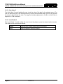
Figures
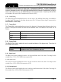
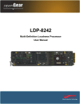
Figure 1-1: 7847FSE Frame Synchronizer Block Diagram ................................................................................... 2
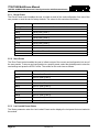
Figure 2-1: Module Rear Panels ........................................................................................................................... 3
Figure 2-2: GPI Input Circuitry .............................................................................................................................. 4
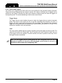
Figure 4-1: Status LEDs ........................................................................................................................................ 7
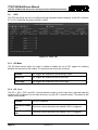
Figure 5-1 : General Tab ....................................................................................................................................... 8
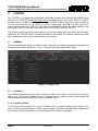
Figure 5-2 : Video Tab......................................................................................................................................... 10
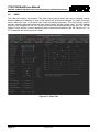
Figure 5-3 : Audio Tab......................................................................................................................................... 16
Figure 5-4 : Audio Proc Ch1-Ch4 Tab................................................................................................................. 19
Figure 5-5 : Utilities Control Tab ......................................................................................................................... 23
Figure 5-6 : GPIO Tab ......................................................................................................................................... 26
Figure 5-7 : Up-Mix Tab ...................................................................................................................................... 27
Figure 5-8 : Down-Mix Tab .................................................................................................................................. 30
Figure 5-9 : IntelliGain Configuration Tab ........................................................................................................... 33
Figure 5-10 : IntelliGain 1 Programs Tab ............................................................................................................ 34
Figure 5-11 : IntelliGain 1 Fault Traps Tab ......................................................................................................... 35
Figure 5-12 : Fault Control Tab ........................................................................................................................... 36
Figure 5-13 : Input Fault Control Tab .................................................................................................................. 38
Figure 5-14 : Fault Traps PGM In-A Tab............................................................................................................. 40
Figure 5-15 : TTX Tab ......................................................................................................................................... 41
Figure 5-16 : Audio/Video Traps Tab .................................................................................................................. 44
Figure 6-1: Location of Jumpers – Top View ...................................................................................................... 45
Figure 6-2: Slot Blocker ....................................................................................................................................... 46
Tables
Table 2-1: GPI Connector Pin Out ........................................................................................................................ 4
Table 5-1: Input Video Standard ......................................................................................................................... 11
Table 5-2: Source X Input ................................................................................................................................... 20
Table 5-3: Source Y Input ................................................................................................................................... 21
Page iv
Revision 1.0
7700/7800 MultiFrame Manual
7847FSE 3G/HD/SD-SDI Advanced Frame Synchronizer with Embedded Audio
REVISION HISTORY
REVISION
DESCRIPTION
DATE
0.1
Preliminary
Sep 2009
0.2
Updated specs to include Additional Delay Mode information
Nov 2009
0.3
Updated “Slot Blocker” section
Aug 2012
0.4
Added card edge LEDs information
Sep 2012
0.5
Added GPI information to Installation section
Oct 2012
0.6
Active Format Descriptor insertion as per SMPTE ST 2016 and
Dolby metadata insertion as per SMPTE ST 2020 removed from features
Added VL pro screen shots
Sep 2013
1.0
Updated entire control section to include latest changes to control set
including +DMX, +UMX, +IG, +2X1 and +TTX options
Mar 2014
Information contained in this manual is believed to be accurate and reliable. However, Evertz assumes no responsibility for the use thereof nor for
the rights of third parties, which may be affected in any way by the use thereof. Any representations in this document concerning performance of
Evertz products are for informational use only and are not warranties of future performance, either expressed or implied. The only warranty offered
by Evertz in relation to this product is the Evertz standard limited warranty, stated in the sales contract or order confirmation form.
Although every attempt has been made to accurately describe the features, installation and operation of this product in this manual, no warranty is
granted nor liability assumed in relation to any errors or omissions unless specifically undertaken in the Evertz sales contract or order confirmation.
Information contained in this manual is periodically updated and changes will be incorporated into subsequent editions. If you encounter an error,
please notify Evertz Customer Service department. Evertz reserves the right, without notice or liability, to make changes in equipment design or
specifications.
Revision 1.0
Page v
7700/7800 MultiFrame Manual
7847FSE 3G/HD/SD-SDI Advanced Frame Synchronizer with Embedded Audio
This page left intentionally blank
Page vi
Revision 1.0
7700/7800 MultiFrame Manual
7847FSE 3G/HD/SD-SDI Advanced Frame Synchronizer with Embedded Audio
1.
OVERVIEW
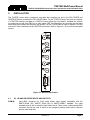
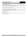
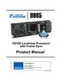
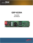
The 7847FSE Frame Synchronizer is designed to re-time a SMPTE 424M (3Gb/s), SMPTE 292M
(1080i/59.94, 1080i/50, 720p/60, 720p/59.94) or SMPTE259M (625i/50, 525i/59.94) input to a local
composite sync signal. When necessary, frames are repeated or dropped to maintain synchronization.
The 7847FSE supports synchronization of both the video and any embedded audio present including
the preservation of all vertical blanking data. When the input video is lost, this module will pass the input
content, freeze the last good frame or generate black video. The frame synchronizers also have the
ability to set the audio delay independently from the video delay. The frame synchronizers can adjust
video parameters such as brightness, contrast, saturation and hue control. The 7847FSE enables the
adjustment of audio parameters such as gain, mixing stereo pairs into monaural and the reassignment
of audio channels if fully supported up to 16 channels of embedded audio.
The 7847FSE is VistaLINK® capable, offering remote monitoring, control and configuration capabilities
via Simple Network Management Protocol (SNMP) giving the flexibility to manage operations, including
signal monitoring and module configuration from SNMP capable control systems (Manager or NMS).
Features:
• Synchronizes 3G, HD-SDI or SD-SDI video signals with embedded audio
• Supports additional frames of video and audio delay
• Program Video output bypass relay protected on power loss
• Programmable output phase with respect to reference input
• Freeze on last good frame, or go to black/blue on loss of video or pass input
• Synchronizes 4 groups of embedded audio
• Adjustable brightness, contrast, saturation
• Full audio processor including channel shuffling, gain and phase inversion
• Protection switching to backup input
• Card edge status LEDs
• VistaLINK® - capable, offering remote control and configuration capabilities via SNMP
Additional features with IntelliGain® Audio and Loudness Processor (+IG) option:
• Consistent audio loudness levels within a channel and/or program
• Automatic detection and level adjust for loud commercials
• Gain control within a program interval to preserve audio dynamic range
• Artifact-free transitions between program and commercials
• Elimination of drastic volume changes during commercials and interstitials
Additional features with +2X1 option:
• Automatic changeover for protection switching between two inputs
• Changeover can be conditional on video loss, black or freeze; and audio loss, over or under
• Provides fault monitoring for all switching conditions
Additional features with +UMX option:
• 2-channel stereo to 5.1 surround sound upmixing
Additional features with +DMX option:
• 5.1 to 2-channel stereo downmixing
Revision 1.0
Page 1
7700/7800 MultiFrame Manual
7847FSE 3G/HD/SD-SDI Advanced Frame Synchronizer with Embedded Audio
Additional features with +TTX option:
• OP-42 and OP-47 World System Teletext (WST) monitoring and processing
• Automatic clear down insertion using GPIs
• Automatic packet error correction and caption substitution
Input Time
Recovery
3G/HD/SD-SDI
Primary Input
3G/HD/SD-SDI
Outputs
A
Smart Input
Selector
Signal
De-Serializer
Video
Recovery
Video Frame
Sync
Audio
De-Embed
Audio Frame
Sync
Data
Recovery
ANC Data
Sync
Video
Processor
1
Audio
Re-Embed
ANC Data
Embedder
2
B
3G/HD/SD-SDI
Back-Up Input
3
Audio/Video
Monitoring
Audio
Processor
(+UMX, +DMX,
+IG options)
+2X1 option
4 GPIs
Data
Conditioner
(+TTX option)
1
VistaLINK®
Interface
2
Genlock
Output Time
Generator
Status
3
Control
4
5
6
Card Edge
Control
Alphanumeric Card Edge
Status Display
Figure 1-1: 7847FSE Frame Synchronizer Block Diagram
Page 2
Revision 1.0
7700/7800 MultiFrame Manual
7847FSE 3G/HD/SD-SDI Advanced Frame Synchronizer with Embedded Audio
2.
INSTALLATION
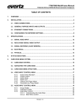
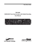
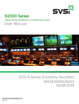
The 7847FSE comes with a companion rear plate that occupies one slot in the 3RU 7800FR and
7800FR-QT frames as well as the 1RU 7801FR frame. For the 7700FR-C frame, two slots are required.
If a 7847FSE module is installed in a 7700FR-C frame without the “slot blocker” installed, the card will
not power-up and will show RED on its main status LED. For information on mounting the rear plate
and inserting the module into the frame see section 3 of the 7700FR manual. Refer to section 6.4 of this
manual for more information on the 7847FSE slot blocker. Refer to Figure 2-1 for the various rear plate
layouts.
Figure 2-1: Module Rear Panels
2.1.
3G, HD AND SDI VIDEO INPUTS AND OUTPUTS
PGM IN:
Input BNC connector for 10-bit serial digital video signals compatible with the
SMPTE 424M (3G), SMPTE 292M (HD) or SMPTE 259M-C standard. The video
standard must be set to match the input video format. There is also a video backup BNC
connector that can be used to switch to an emergency backup video feed in case the
primary video feed fails.
Revision 1.0
Page 3
7700/7800 MultiFrame Manual
7847FSE 3G/HD/SD-SDI Advanced Frame Synchronizer with Embedded Audio
PGM OUT:
2.2.
Three output BNC connectors with serial component video in the same format as the
input video. These outputs contain the input video synchronized to the GENLOCK input
video or to the free running internal oscillator if Genlock is not present. The top output is
protected by a bypass relay, which will activate in the event of power loss to the module.
There is a second and third identical output that is not bypass protected.
GENLOCK REFERENCE
For proper synchronization of the output video, the frame synchronizer must be locked to a genlock
signal.
GENLOCK:
2.3.
There is an input BNC for connecting an analog Genlock reference. The genlock signal
may be tri-level sync, NTSC or PAL, and is auto-detected by the module. This input can
be optionally configured as a fourth output from the 7847FSE module. In this case the
genlock signal will need to be obtained from the 7800FR internal genlock frame
distribution.
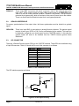
GPI CONNECTOR
There are 4 General Purpose Inputs (GPIs) on the 7847FSE modules. These GPIs are interfaced using
a 9-pin DB connector. Table 2-1 shows the Pin-out of this connector is as follows:
DB-9 Pin
1
2
3
4
5
6
7
8
9
Name
GPI1
Metadata Txn
Metadata Rxp
GPI2
GPI3
Ground
Metadata Txp
Metadata Rxn
GPI4
Table 2-1: GPI Connector Pin Out
The GPI interface operates as follows:
+5
VDC
3.6 K
GPI
GPI
Command
GND
Figure 2-2: GPI Input Circuitry
Page 4
Revision 1.0
to
internal
circuit
7700/7800 MultiFrame Manual
7847FSE 3G/HD/SD-SDI Advanced Frame Synchronizer with Embedded Audio
3.
TECHNICAL DESCRIPTION
3.1.
SPECIFICATIONS
3.1.1. Serial Video Input Inputs A & B
Standard:
Connector:
SMPTE 424M (3Gb/s) 1080p (-3G models)
SMPTE 292M (1.5Gb/s), 1080i, 1035i, 720p
SMPTE 259M (270Mb/s) 525i, 625i
BNC per IEC 61169-8 Annex A
3.1.2. Input Equalization
SD:
HD:
3G:
Automatic to 300m @ 270Mb/s with Belden 1694A or equivalent cable
Automatic to 115m @ 1.5Gb/s with Belden 1694A or equivalent cable
Automatic to 80m @ 3Gb/s with Belden 1694A or equivalent cable
3.1.3. Return Loss
SD:
HD:
3G:
> 15dB up to 270MHz
> 13dB up to 1.5GHz
> 10dB up to 3.0GHz
3.1.4. Serial Video Outputs
Number of Outputs:
Connectors:
Signal Level:
DC Offset:
Rise and Fall Time:
Overshoot:
Wide Band Jitter:
3 (1 output is bypass relay protected)
BNC per IEC 61169-8 Annex A
800mV nominal
0V ±0.5V
900ps nominal (SD)
200ps nominal (HD)
< 10% of amplitude
< 0.2 UI
3.1.5. Genlock Input
Type:
Connector:
Termination:
NTSC or PAL Color Black 1V p-p, or Composite bi-level sync (525i/59.94 or
625i/50) 300mV
HD Tri-level Sync
BNC per IEC 61169-8 Annex A
75Ω (dip-switch selectable)
3.1.6. Processing Functions Video
Black Level:
±7%
Luminance Gain:
±6dB
Chrominance Gain: ±6dB
3.1.7. Audio
Gain:
Remapping:
±24dB
Any input or mono mix of any L/R pair to any output
Revision 1.0
Page 5
7700/7800 MultiFrame Manual
7847FSE 3G/HD/SD-SDI Advanced Frame Synchronizer with Embedded Audio
3.1.8. Electrical
Voltage:
Power:
EMI/RFI:
+12V DC
15W
Complies with FCC Part 15, Class A EU EMC Directive
3.1.9. Physical (Number of Slots)
350FR:
7700FR-C:
7800FR:
7801FR:
Page 6
2
2
1
1
Revision 1.0
7700/7800 MultiFrame Manual
7847FSE 3G/HD/SD-SDI Advanced Frame Synchronizer with Embedded Audio
4.
STATUS INDICATORS
4.1.
MODULE STATUS LEDS
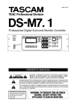
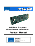
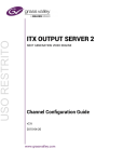
The 7847FSE has several LEDs mounted on the front card edge to provide the user with quick
feedback on the status of the card. Figure 4-1 depicts status LEDs on the 7847FSE.
Module Status
Local Fault
7847FSE-3G
Shaft
Encoder
(not used)
PGM B
PRESENT
GRP 1
PRESENT
PGM A
REF
PRESENT PRESENT
GRP 3
PRESENT
GRP 2
PRESENT
VIDEO
SOURCE
LINK/ACT
GRP 4
PRESENT
10/100
Figure 4-1: Status LEDs
MODULE STATUS:
This Green LED will be On when the module is operating properly.
LOCAL FAULT:
This Red LED will be On when an essential module input is missing or the
module has another fault.
IN PRESENT:
The IN PRESENT LED will be green when a valid input signal is present on the
PGM A BNC. It will be red when missing an input signal. It will blink between
red and green when an invalid input signal is presented.
REF PRESENT:
The REF PRESENT LED will be green when a valid reference signal is present
on the REF IN BNC. It will be red when missing a reference signal. It will blink
between red and green when an invalid genlock signal is presented. This LED
will also be red when genlocking is turned off (lock to video).
GRP1 PRESENT:
This LED will be Green when embedded audio Group 1 is present and Red
when embedded audio Group 1 is not present.
GRP2 PRESENT:
This LED will be Green when embedded audio Group 2 is present and Red
when embedded audio Group 2 is not present.
GRP3 PRESENT:
This LED will be Green when embedded audio Group 3 is present and Red
when embedded audio Group 3 is not present.
GRP4 PRESENT:
This LED will be Green when embedded audio Group 4 is present and Red
when embedded audio Group 4 is not present.
VIDEO SOURCE:
This LED with be Green when the input video source is PGM IN A and Yellow
when the input source is PGM IN B.
Revision 1.0
Page 7
7700/7800 MultiFrame Manual
7847FSE 3G/HD/SD-SDI Advanced Frame Synchronizer with Embedded Audio
5.
CONTROL
The 7847FSE is controlled using VistaLINK®. VistaLINK® operates using Ethernet and SNMP control
protocols. The 7847FSE Series DOES NOT HAVE card edge controls. As a result, 7700FC or 7800FC
modules must be installed in all frames that house a 7847FSE module. Refer to the Evertz website for
the most recent firmware for the 7700FC or 7800FC. When using VistaLINK® it is also important to
ensure that the most recent 7847FSE “.JAR” control file is installed. Refer to the Evertz website for the
most recent “.JAR” file. The name of the file will be “VLPROPROD_7847FSE-3G.JAR”.
The following sections describe module controls in terms of the parameters found within the VistaLINK®
screens for the 7847FSE Series. As additional features and options are released, additional sections
will be appended to this manual to show those control screens.
5.1.
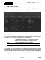
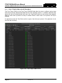
GENERAL
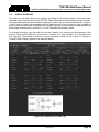
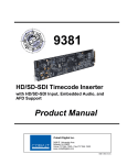
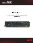
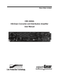
The General tab allows the user to obtain revision information and details regarding the hardware and
firmware of the module. Sections 5.1.1 to 5.1.7 describe the various parameters in detail.
Figure 5-1 : General Tab
5.1.1. CardName
The CardName reports the product name or product variable of the module. This name will include any
options (e.g. +IG) that are included as well. If this name does not match the name of the product that
was purchased then some functions may not be available for use.
5.1.2. Firmware Version
The Firmware Version reports the version of firmware that is currently installed and running on the
module. Check the Evertz website to ensure that the version of firmware is the latest that is available. If
the firmware version is older then it is recommended that the module be upgraded.
Page 8
Revision 1.0
7700/7800 MultiFrame Manual
7847FSE 3G/HD/SD-SDI Advanced Frame Synchronizer with Embedded Audio
5.1.3. FPGA Version
The FPGA Version reports the version of the FPGA bit file that is currently installed and running on the
module.
5.1.4. Creation Date
The Creation Date reports the creation date of the firmware that is currently installed and running on the
module.
5.1.5. Board Name
The Board Name reports the name of the physical module.
5.1.6. Board Revision
The Board Revision reports the revision of the physical module.
5.1.7. Board Serial Number
The Board Serial Number reports the serial number of the module.
Revision 1.0
Page 9
7700/7800 MultiFrame Manual
7847FSE 3G/HD/SD-SDI Advanced Frame Synchronizer with Embedded Audio
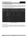
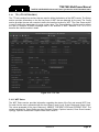
5.2.
VIDEO
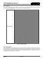
The Video tab contains five sections. The Video Control section allows the user to configure settings
that are related to the handling of video on the card as well as reference settings. The Video Processing
section allows the user to set some basic video processing parameters. The Video Monitor section
provides valuable information about the input video sources and the genlock input. The 2X1 Settings
section is only available with the +2X1 option and controls the switching mode for the card. The SDI VBI
Bypass Control section is used to determine which waveforms are passed in the VBI. Sections 5.2.1 to
5.2.18 describe the various controls in detail.
Figure 5-2 : Video Tab
Page 10
Revision 1.0
7700/7800 MultiFrame Manual
7847FSE 3G/HD/SD-SDI Advanced Frame Synchronizer with Embedded Audio
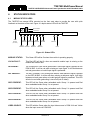
5.2.1. Input Video Standard
The Input Video Standard control enables the user to set the input video standard being used.
Interlaced video formats are shown with the number of fields per second. Progressive formats are
shown with the number of frames per second. When the input standard is set to Auto, the module will
auto detect the video standard. The full set of available input video standards includes:
Auto
625i/50
525i/59.94
720p/50
720p/59.94
720p/60
1035i/59.94
1035i/60
1080i/50
1080i/59.94
1080i/60
1080p/23.98sF
1080p/24sF
1080p/50 (425M level A)
1080p/59.94 (425M level A)
1080p/60 (425M level A)
1080p/50 (425M level B)
1080p/59.94 (425M level B)
1080p/60 (425M level B)
1080p/24
1080p/23.98
1080p/25
1080p/30
1080p/29.97
720p/24
720p/23.98
2048x1080p/24
2048x1080p/23.98
2048x1080p/24sF
2048x1080p/23.98sF
Table 5-1: Input Video Standard
5.2.2. Input Video Source
The Input Video Source control enables the user to set the source of video input for the card. The
values for this control are as follows:
PGM In-A
Use the video connected to BNC PGM In-A as the source.
PGM In-B
Use the video connected to BNC PGM In-B as the source.
Auto 2X1
Use the output of the auto changeover as the source (+2X1 option only.)
Revision 1.0
Page 11
7700/7800 MultiFrame Manual
7847FSE 3G/HD/SD-SDI Advanced Frame Synchronizer with Embedded Audio
5.2.3. Reference Select
The Reference Select control enables the user to set the source of video reference for the card. When
the card is used in the 7700FR-G or the 7800FR, frame reference inputs may be used. The values for
this control are as follows:
External
Lock to the local genlock reference.
Frame Ref1
Lock to Frame Ref 1 on the 7700FR-G or the 7800FR.
Frame Ref2
Lock to Frame Ref 2 on the 7700FR-G or the 7800FR.
Video Input Source
Lock to the incoming input video as defined by the Input Video
Source control.
PGM In-A
Lock to the input video connected to BNC PGM In-A.
PGM In-B
Lock to the input video connected to BNC PGM In-B.
Note that if the selected genlock reference disappears or is not valid, the card will
lock to incoming video.
5.2.4. V Phase Offset
The V Phase Offset control enables the user to set the vertical timing of the output video with respect to
the reference input set by the Reference Select control. There are separate settings of V phase offset
for each output video type. Setting this control to 0 keeps the output video frame aligned with the
reference.
Increasing the value will delay the output video in one-line increments of the output video standard. In
order to advance the vertical timing of the output video with respect to the reference, set the control to
the maximum total number of lines of the output video minus the number of lines that you wish to
advance the output video, (e.g. for 1080i/59.94 output video, the total number of lines is 1125, so to
advance the output video 5 lines set the value to 1120.) When increasing the V Phase Offset value
causes it to go beyond the limit of the frame buffer, the V Phase Offset will wrap to the beginning of the
frame buffer, resulting in a change of one frame of throughput delay between the input and the output.
Note: The slider is available for selecting H and V Phase Offsets. To increment,
click on the right hand side of the slider. To decrement click on the left hand side
of the slider. The slider can also be selected and dragged across the available
range if gross movement is desired.
5.2.5. H Phase Offset
The H Phase Offset control enables the user to set the horizontal timing of the output video with respect
to the reference input set by the Reference Select control. There are separate settings of H phase
offset for each output video type. Setting this control to 0 keeps the output video line aligned with the
reference.
Page 12
Revision 1.0
7700/7800 MultiFrame Manual
7847FSE 3G/HD/SD-SDI Advanced Frame Synchronizer with Embedded Audio
Increasing the value will delay the output video in one-sample increments. In order to advance the
horizontal timing of the output video with respect to the genlock video, set the control to the maximum
number of samples per line for the output video standard minus the number of samples that you wish to
advance the output video, (e.g. for 1080i/59.94 input video the total number of samples per line is 2200,
so to advance the output video 5 samples set the value to 2195.)
5.2.6. Video Delay
The Video Delay control enables the user to set the value of the additional video delay to be added to
the signal path. The range for the delay adjustments is 0 to 31 frames. Video delay is incremented or
decremented in 1 frame steps.
5.2.7. Freeze Mode
The Freeze Mode control enables the user to set the behavior of the output when the input video is not
present. The output will freeze the frame with the selected value. The values for this control are as
follows:
Frame
Output the last stored frame of video.
Pass
Output what is on the input even if it is bad video or noise.
Black
Output black.
Blue
Output blue.
5.2.8. Bypass Relay
The Bypass Relay control enables the user to control the behavior of the bypass relay. The values for
this control are as follows:
Disable
Disables the relay. (Relay will still activate on a power loss.)
Enable
Enables the relay until it is disabled by the user.
5.2.9. Black Level
The Black Level control enables the user to set the overall black level of the video. The range for this
control is from -7.31 to 7.31 %IRE in increments of 0.6.
5.2.10. Luma Level
The Luma Level control enables the user to set the overall luma level of the video. The range for this
control is from -6.02 to 5.99 dB in increments of 0.03.
5.2.11. Chroma Level
The Chroma Level control enables the user to set the overall chroma level of the video. The range for
this control is from -6.02 to 5.99 dB in increments of 0.03.
Revision 1.0
Page 13
7700/7800 MultiFrame Manual
7847FSE 3G/HD/SD-SDI Advanced Frame Synchronizer with Embedded Audio
5.2.12. Hue
The Hue control enables the user to set the hue of the video signal. The range for this control is from 20 to 20 degrees in 0.5 degree increments.
5.2.13. PGM IN A Video Standard
The PGM IN A Video Standard parameter reports if a valid video signal is presented to PGM IN A and
what standard has been detected when it is present.
5.2.14. PGM IN B Video Standard
The PGM IN B Video Standard parameter reports if a valid video signal is presented to PGM IN B and
what standard has been detected when it is present.
5.2.15. Current Video Input
The Current Video Input parameter reports what input BNC has been selected to pass through the
module. This parameter will also indicate if the selected BNC was selected by a GPI or the 2X1 auto
changeover, (if applicable).
5.2.16. Genlock Reference Standard
The Genlock Reference Standard parameter reports if a valid video reference has been supplied to the
reference source selected by the Reference Select control and indicates the standard that is detected.
5.2.17. Switch Mode (+2X1 Option Only)
The Switch Mode control enables the user to set the behavior of the automatic changeover. The
conditions used to determine the health of each input are described in sections 5.11 and 5.12. The
values for this control are as follows:
Auto
Switches between PGM In-A and PGM In-B depending on state of
current input.
PGM In-A Switch
Back
Behaves the same as Auto but always switches back to PGM In-A
if it is healthy.
PGM In-B Switch
Back
Behaves the same as Auto but always switches back to PGM In-B
if it is healthy.
Page 14
Revision 1.0
7700/7800 MultiFrame Manual
7847FSE 3G/HD/SD-SDI Advanced Frame Synchronizer with Embedded Audio
5.2.18. SD VBI Bypass
The SD VBI Bypass controls, which include CC, VITC 1, VITC 2, WSS, VI and WST 1-5, are used to
allow VBI lines in SD video to pass through the module. The controls for all VBI types are managed in
the same manner so for the sake of brevity only the CC control is explained.
The Enable checkbox allows the user to select whether CC VBI should be passed to the output.
Checking this box will enable this function.
The Input control enables the user to set the incoming video line in which CC VBI is present. The range
of this control is variable depending on the input video standard.
The Follow Input checkbox enables the user to set the outgoing video line to the same line as the
incoming video. Checking this box will enable this function.
The Output control enables the user to set the outgoing video line in which CC VBI will be inserted. This
control is disabled if the Follow Input checkbox is checked. The range of this control is variable
depending on the input video standard.
Note that the WST 1-5 controls are disabled if the +TTX option is applied to the
module. See section 5.13 for details regarding the +TTX option.
Revision 1.0
Page 15
7700/7800 MultiFrame Manual
7847FSE 3G/HD/SD-SDI Advanced Frame Synchronizer with Embedded Audio
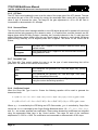
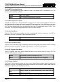
5.3.
AUDIO
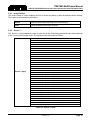
The Audio tab contains two sections. The Audio Control section allows the user to configure settings
that are related to the handling of audio on the card. The Audio Monitor section provides valuable
information about the status of the Sample Rate Converters (SRC) as well as the audio format of inputs
to the card. Sections 5.3.1 to 5.3.7 describe the various controls in detail.
Figure 5-3 : Audio Tab
5.3.1. Audio Delay
The Audio Delay control enables the user to set the audio delay. The range of this control is 0 to 1,000
ms in 0.0208 ms increments. (0.0208 ms is equivalent to one 48 kHz audio sample.)
Page 16
Revision 1.0
7700/7800 MultiFrame Manual
7847FSE 3G/HD/SD-SDI Advanced Frame Synchronizer with Embedded Audio
5.3.2. SRC Mode
The SRC Mode control enables the user to set the mode for the sample rate converters. The values for
this control are as follows:
Enable
Enables the sample rate converters for PCM audio.
Bypass
Bypasses the sample rate converters. This setting should be used
for non-PCM audio (i.e. Dolby E).
Auto
The module will automatically detect PCM and non-PCM audio
and automatically turn on/off the SRCs as required. Note that all
SRCs are set to bypass as soon as a source of non-PCM audio is
detected within any of the 16 internally processed audio channels.
5.3.3. Embedder Group 1-4
The Embedder Group control enables the user to set the mode of the audio embedders. The module
has four audio embedders that each insert one group of audio into the outgoing serial digital video. For
the sake of brevity, only the control for Audio Embedder 1 is discussed in further detail. The values for
this control are as follows:
Disable
Audio embedding for group 1 is disabled.
Enable
Audio embedding for group 1 is enabled.
5.3.4. C-Bit Mode
The C-Bit Mode control enables the user to set the behavior of the audio embedders when dealing with
the channel status bit of AES audio. The values for this control are as follows:
Preserve
Preserves or passes the C-Bit settings from audio inputs to audio
outputs.
Replace
Replace the C-Bit settings with an internal counter.
5.3.5. Audio Mute Mode
The Audio Mute Mode control enables the user to set the behavior of the audio embedders when input
audio is missing. The values for this control are as follows:
Pass
Pass the audio inputs to audio outputs.
Mute on Video
Error
Mute the audio outputs.
Revision 1.0
Page 17
7700/7800 MultiFrame Manual
7847FSE 3G/HD/SD-SDI Advanced Frame Synchronizer with Embedded Audio
5.3.6. De-Embedded Ch1 & Ch2
The De-Embedded Ch1 & Ch2 parameter reports the Input Type, Input Phase and Phase Status of
each pair of embedded audio channels. The status for each channel pair is the same so for the sake of
brevity, only the status of Ch1 & Ch 2 are described in detail.
The Input Type reports the type of audio on channels 1 and 2 together. The status will display the
values PCM, Dolby E, AC3 or Not Present.
The Input Phase reports the line where the Dolby E packet begins in terms of the input video standard.
If the Input Type is not Dolby E then the status will display N/A.
The Phase Status reports the status of the Dolby E Input Phase measurement. The status will display
the values Ideal, Good, Bad or N/A.
5.3.7. SRC Status
The SRC Status parameter displays the status of the sample rate converters. The status will display
either Enabled or Bypassed.
Page 18
Revision 1.0
7700/7800 MultiFrame Manual
7847FSE 3G/HD/SD-SDI Advanced Frame Synchronizer with Embedded Audio
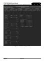
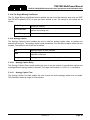
5.4.
AUDIO PROCESSING
The Audio Proc tab allows the user to configure the settings of the audio processor. There are sixteen
individual output channel mixers in the 7847FSE. These output channel mixers perform audio inversion,
audio gain adjustment and audio channel swapping for each of the 16 output audio channels. Using the
X and Y inputs of each output channel mixer an additional level of mono-mixing is also available for
each channel of output audio. Embedded audio outputs are driven with the same audio generated using
these output channel mixers. Sections 5.4.1 to 5.4.6 describe the controls in detail.
For the sake of brevity, only the Audio Proc for the Channels 1-4 control tab will be discussed in this
manual. Control radial buttons for Channels 5-8, Channels 9-12, and Channels 13-16 are identical in
their operation. The controls for Channel 1 will be described in detail, as the controls for Channel 2,
Channel 3 and Channel 4 operate in an identical fashion.
Figure 5-4 : Audio Proc Ch1-Ch4 Tab
Revision 1.0
Page 19
7700/7800 MultiFrame Manual
7847FSE 3G/HD/SD-SDI Advanced Frame Synchronizer with Embedded Audio
5.4.1. Source X
The Source X control enables the user to route one of the 16 internally processed input audio channels
to the X input of the channel mixer. The values for this control are as follows:
Source X Input
Mute
De-embedder Ch 1
De-embedder Ch 2
De-embedder Ch 3
De-embedder Ch 4
De-embedder Ch 5
De-embedder Ch 6
De-embedder Ch 7
De-embedder Ch 8
De-embedder Ch 9
De-embedder Ch 10
De-embedder Ch 11
De-embedder Ch 12
De-embedder Ch 13
De-embedder Ch 14
De-embedder Ch 15
De-embedder Ch 16
IntelliGain Ch 1 (only with +IG option)
IntelliGain Ch 2 (only with +IG option)
IntelliGain Ch 3 (only with +IG option)
IntelliGain Ch 4 (only with +IG option)
IntelliGain Ch 5 (only with +IG option)
IntelliGain Ch 6 (only with +IG option)
IntelliGain Ch 7 (only with +IG option)
IntelliGain Ch 8 (only with +IG option)
Up-Mix L (only with +UMX option)
Up-Mix R (only with +UMX option)
Up-Mix C (only with +UMX option)
Up-Mix LFE (only with +UMX option)
Up-Mix Ls (only with +UMX option)
Up-Mix Rs (only with +UMX option)
Down-Mix L (only with +DMX option)
Down-Mix R (only with +DMX option)
Down-Mix Mono (only with +DMX option)
Table 5-2: Source X Input
5.4.2. Gain Adjust X
The Gain Adjust X control enables the user to set the value of the gain for the selected source. The
user can adjust the gain of the selected source by moving the associated slider control left to decrease
the value or right to increase the value. The range for the gain adjustments is -24 dB to +24 dB. Gain is
incremented or decremented in 0.1 dB steps.
Page 20
Revision 1.0
7700/7800 MultiFrame Manual
7847FSE 3G/HD/SD-SDI Advanced Frame Synchronizer with Embedded Audio
5.4.3. Invert Enable X
The Invert Enable X control enables the user to invert the phase or pass the selected audio channel.
The values for this control are as follows:
Normal
Pass the audio channel through with no processing.
Invert
Invert the phase of the audio channel.
5.4.4. Source Y
The Source Y control enables the user to route one of the 16 internally processed input audio channels
to the Y input of the channel mixer. The values for this control are as follows:
Source Y Input
Mute
De-embedder Ch 1
De-embedder Ch 2
De-embedder Ch 3
De-embedder Ch 4
De-embedder Ch 5
De-embedder Ch 6
De-embedder Ch 7
De-embedder Ch 8
De-embedder Ch 9
De-embedder Ch 10
De-embedder Ch 11
De-embedder Ch 12
De-embedder Ch 13
De-embedder Ch 14
De-embedder Ch 15
De-embedder Ch 16
IntelliGain Ch 1 (only with +IG option)
IntelliGain Ch 2 (only with +IG option)
IntelliGain Ch 3 (only with +IG option)
IntelliGain Ch 4 (only with +IG option)
IntelliGain Ch 5 (only with +IG option)
IntelliGain Ch 6 (only with +IG option)
IntelliGain Ch 7 (only with +IG option)
IntelliGain Ch 8 (only with +IG option)
Up-Mix L (only with +UMX option)
Up-Mix R (only with +UMX option)
Up-Mix C (only with +UMX option)
Up-Mix LFE (only with +UMX option)
Up-Mix Ls (only with +UMX option)
Up-Mix Rs (only with +UMX option)
Down-Mix L (only with +DMX option)
Down-Mix R (only with +DMX option)
Down-Mix Mono (only with +DMX option)
Table 5-3: Source Y Input
Revision 1.0
Page 21
7700/7800 MultiFrame Manual
7847FSE 3G/HD/SD-SDI Advanced Frame Synchronizer with Embedded Audio
5.4.5. Gain Adjust Y
The Gain Adjust Y control enables the user to set the value of the gain for the selected source. The
user can adjust the gain of the selected source by moving the associated slider control left to decrease
the value or right increase the value. The range for the gain adjustments is -24 dB to +24 dB. Gain is
adjusted in 0.1 dB increments.
5.4.6. Invert Enable Y
The Invert Enable Y control enables the user to invert the phase or pass the selected audio channels.
The values for this control are as follows:
Normal
Pass the audio channel through with no processing.
Invert
Invert the phase of the audio channel.
Page 22
Revision 1.0
7700/7800 MultiFrame Manual
7847FSE 3G/HD/SD-SDI Advanced Frame Synchronizer with Embedded Audio
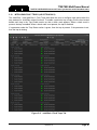
5.5.
UTILITIES CONTROL
The Utilities Control tab contains three sections. The Utilities Control and Last Loaded Preset sections
allow the user to configure settings related to the storing and recalling of presets. The 7847FSE is
capable of storing and retrieving 10 user presets. The Preset Load Triggers section allows the user to
define actions that are used to load specific presets. Sections 5.5.1 to 5.5.4 describe the various
controls in detail.
Figure 5-5 : Utilities Control Tab
There may be a slight disturbance in the operation of the card while the new preset
is being recalled.
Revision 1.0
Page 23
7700/7800 MultiFrame Manual
7847FSE 3G/HD/SD-SDI Advanced Frame Synchronizer with Embedded Audio
5.5.1. Recall Preset
The Recall Preset control enables the user to initiate a recall of the card configuration from one of the
user presets or reset the card to factory defaults. The values for this control are as follows:
None
Factory Default
User 1
User 2
User 3
User 4
User 5
User 6
User 7
User 8
User 9
User 10
No Presets will be recalled
All controls for the card will revert to defaults
Recall User Preset 1
Recall User Preset 2
Recall User Preset 3
Recall User Preset 4
Recall User Preset 5
Recall User Preset 6
Recall User Preset 7
Recall User Preset 8
Recall User Preset 9
Recall User Preset 10
5.5.2. Store Preset
The Store Preset control enables the user to initiate a store of the current card configuration into one of
the user presets. To store a card configuration to a specific preset, select the desired preset to store the
card settings and press the APPLY button. The values for this control are as follows:
None
No Presets will be stared
User 1
Store to User Preset 1
User 2
Store to User Preset 2
User 3
Store to User Preset 3
User 4
Store to User Preset 4
User 5
Store to User Preset 5
User 6
Store to User Preset 6
User 7
Store to User Preset 7
User 8
Store to User Preset 8
User 9
Store to User Preset 9
User 10
Store to User Preset 10
5.5.3. Last Loaded Preset Status
The Status parameter under the Last Loaded Preset section displays the last preset that was loaded to
the module.
Page 24
Revision 1.0
7700/7800 MultiFrame Manual
7847FSE 3G/HD/SD-SDI Advanced Frame Synchronizer with Embedded Audio
5.5.4. Preset Load Triggers
The Preset Load Triggers section allows the user to set conditions for the automatic loading of presets.
These are the same presets that are stored in section 5.5.2 above. A different set of triggers can be
defined for each preset. Selecting the radio button beside the desired preset will load the triggers for
that specific preset. The controls pertaining to this function are as follows:
Trigger Source
The Trigger Source control enables the user to select the triggers that are used to load each
preset. The values for this control are GPI 1-4 and the Operating Video Standard. The GPI 1-4
triggers will load a preset when that specific GPI is activated. The Operating Video Standard
trigger will load a preset when the detected input video standard (see section 5.2.14 and 5.2.15)
matches the standard set by this parameter.
Logic
The Logic control enables the user to set the condition for how the trigger sources are used. The
values for this control are OR and AND. The OR condition will cause a preset to load if any one
of the trigger sources are satisfied. The AND condition will cause a preset to load only if all of
the trigger sources are satisfied.
Note: The GPI triggers used for preset loading are also configured in the GPIO tab as
described in section 5.6. As such, a GPI may trigger several events at once so it is
important to take caution when configuring a GPI.
Revision 1.0
Page 25
7700/7800 MultiFrame Manual
7847FSE 3G/HD/SD-SDI Advanced Frame Synchronizer with Embedded Audio
5.6.
GPIO
The GPIO tab allows the user to configure settings associated with the behavior of the GPIs. Sections
5.6.1 to 5.6.2 describe the various controls in detail.
Figure 5-6 : GPIO Tab
5.6.1. GPI Mode
The GPI Mode control allows the users to enable or disable the use of GPI triggers for switching
between the two inputs of the module. The values for this control are as follows:
Disabled
GPI triggers are disabled for the switching of inputs.
Active Low
GPI triggers are enabled and set to active low.
Active High
GPI triggers are enabled and set to active high.
5.6.2. GPI 1 to 4
The GPI 1, GPI 2, GPI 3 and GPI 4 controls allow the users to set the input that is selected when the
respective GPI is triggered. For the sake of brevity, only the GPI 1 control is shown. The values for this
control are as follows:
Disabled
The GPI is disabled.
Video Source PGM
In-A
PGM In-A is set as the input to the module if GPI 1 is triggered.
Video Source PGM
In-B
PGM In-B is set as the input to the module if GPI 1 is triggered.
Page 26
Revision 1.0
7700/7800 MultiFrame Manual
7847FSE 3G/HD/SD-SDI Advanced Frame Synchronizer with Embedded Audio
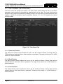
5.7.
UP-MIX (+UMX OPTION ONLY)
The Up-Mix tab contains two sections. The Control section allows the user to set various parameters
used to define the behavior of the upmix engine to produce the desired output. The Audio Source
Select section allows the user to select the audio channels that will be used to produce a surround
upmix. Sections 5.7.1 to 5.7.11 describe the various controls in detail.
Figure 5-7 : Up-Mix Tab
5.7.1. Up-Mix Mode
The Up-Mix Mode control allows the user to set whether the upmix engine will automatically determine
if the audio needs to be upmixed. The values for this control are as follows:
Auto
The upmixer will determine if 5.1 or stereo is present. If stereo is
present it will upmix the audio to 5.1, and pass if 5.1 is seen.
Force
The upmixer will always upmix the incoming audio.
Disable
The upmixer will not upmix the audio and just pass it through.
5.7.2. Centre Width
The Centre Width control allows the user to adjust the width of the front centre sound in the perceived
sound image when listening to upmixed audio. It mainly affects the perception of speech and dialogue.
A narrower centre width will cause the front centre sound to come primarily from the centre speaker. A
wider centre width will cause the front centre sound to come from the centre, left and right speakers. To
adjust the centre width of the upmix control, drag the slider right to increase the value of the centre
width or drag the slider left to decrease the value of the centre width. The value range is 0 to 7 in
increments of 1. The default value is 3.
Revision 1.0
Page 27
7700/7800 MultiFrame Manual
7847FSE 3G/HD/SD-SDI Advanced Frame Synchronizer with Embedded Audio
5.7.3. Surround Depth
The Surround Depth control allows the user to adjust the depth of surround sound in the perceived
sound image when listening to upmixed audio. More sound will be directed to the front speakers
(centre, left and right speakers) if a shallower surround depth is selected. If a deeper surround depth is
selected, more sound will be shifted to the surround speakers. To adjust the depth of the surround, drag
the slider right to increase the depth or drag it left to decrease the depth. The value range is 0 to 7 in
increments of 1. The default value is 3.
5.7.4. Surround Delay
This Surround Delay control allows the user to adjust the amount of time that the surround sound will be
delayed against other channels. Proper amount of surround delay will provide a good perception of
surround sound. To adjust the delay of the upmix surround, drag the slider to the right to increase the
delay or drag it to the left to decrease the delay in milliseconds. The value range is 4 to 20 ms in
increments of 0.021 ms. The default value is 10 ms.
5.7.5. LFE Gain
The LFE Gain control allows the user to adjust the gain of the LFE channel after audio is upmixed. The
values for this control are as follows:
Mute
Mute the LFE channel in the upmixed audio.
+ 0 dB
Apply 0 dB gain to the generated LFE channel.
-1.5 dB
Apply –1.5 dB gain to the generated LFE channel.
-3.0 dB
Apply –3.0 dB gain to the generated LFE channel.
-4.5 dB
Apply –4.5 dB gain to the generated LFE channel.
-6.0 dB
Apply –6.0 dB gain to the generated LFE channel.
-7.5 dB
Apply –7.5 dB gain to the generated LFE channel.
-9.0 dB
Apply –9.0 dB gain to the generated LFE channel.
5.7.6. Sound Direction Detect Rate
The Sound Direction Detect Rate control allows the user to adjust the detection rate of sound direction.
The upmixer constantly calculates the sound image that would be perceived from the stereo audio
input. If the sound direction shifts in the sound image, the upmixer changes the output sound direction
accordingly by switching the amount of sound going to different speakers. If a faster detection rate is
selected, the sound direction switching may sound more dramatic, but may also be felt as unnatural.
On the other hand, a slower detection rate would sound dull and uninteresting. To adjust the detection
rate of the sound direction, drag the slider to the right to increase the rate or drag it to the left to
decrease the rate. The value range is 0 to 7 in steps of 1. The default is level 4.
5.7.7. Soft Switch Duration
The Soft Switch Duration control allows the user to adjust the transition time when the upmix module
switches modes from 5.1 bypass to upmix and vice versa. The duration can range from 5 to 200 ms in
steps of 1 ms.
Page 28
Revision 1.0
7700/7800 MultiFrame Manual
7847FSE 3G/HD/SD-SDI Advanced Frame Synchronizer with Embedded Audio
5.7.8. Stereo or 5.1
The Stereo or 5.1 parameter reports the configuration of the incoming audio as 2.0 or 5.1.
5.7.9. Up-Mix Status
The Up-Mix Status parameter reports the state of the upmix engine.
5.7.10. Up-Mix Source
The Up-Mix Source control allows the user to set the stereo audio pair that will be used as the source
for the upmix. The values for this control are as follows:
5.1/2.0 L and R
Use the two channels set by the 5.1/2.0 L and 5.1/2.0 R Audio
Source Select controls.
Stereo L and R
Use the two channels set by the Stereo L and Stereo R Audio
Source Select controls.
5.7.11. Audio Source Select
The 5.1/2.0 L, 5.1/2.0 R, 5.1 C, 5.1 LFE, 5.1 Ls, 5.1 Rs, Stereo L and Stereo R controls enable the user
to route one of the 16 internally processed input audio channels to each input of the upmix engine. For
the sake of brevity, only the 5.1/2.0L selection control is shown. Note that the channels selected for 5.1
C, 5.1 LFE, 5.1 Ls and 5.1 Rs are used to determine if the incoming audio configuration is 5.1. If these
channels are silent then the configuration is considered stereo and the upmix engine will be initiated.
The values for these controls are as follows:
De-embedder Ch 1
De-embedder Ch 2
De-embedder Ch 3
De-embedder Ch 4
De-embedder Ch 5
De-embedder Ch 6
De-embedder Ch 7
De-embedder Ch 8
5.1/2.0 L
De-embedder Ch 9
De-embedder Ch 10
De-embedder Ch 11
De-embedder Ch 12
De-embedder Ch 13
De-embedder Ch 14
De-embedder Ch 15
De-embedder Ch 16
Mute
Revision 1.0
Page 29
7700/7800 MultiFrame Manual
7847FSE 3G/HD/SD-SDI Advanced Frame Synchronizer with Embedded Audio
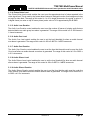
5.8.
DOWN-MIX (+DMX OPTION ONLY)
The Down-Mix tab contains three sections. The Source Selection section allows the user to select the
audio channels that will be used to produce a stereo downmix. The Type section allows the user to set
various parameters used to define the behavior of the downmix engine to produce the desired output.
The Control section provides controls for additional customization of the downmix process. Sections
5.8.1 to 5.8.7 describe the various controls in detail.
Figure 5-8 : Down-Mix Tab
5.8.1. Source Select
The L Source, R Source, C Source, LFE Source, Ls Source and Rs Source controls enable the user to
route one of the 16 internally processed input audio channels to each input of the downmix engine. For
the sake of brevity, only the L Source selection control is shown. The values for these controls are as
follows (on the next page):
Page 30
Revision 1.0
7700/7800 MultiFrame Manual
7847FSE 3G/HD/SD-SDI Advanced Frame Synchronizer with Embedded Audio
L Source
De-embedder Ch 1
De-embedder Ch 2
De-embedder Ch 3
De-embedder Ch 4
De-embedder Ch 5
De-embedder Ch 6
De-embedder Ch 7
De-embedder Ch 8
De-embedder Ch 9
De-embedder Ch 10
De-embedder Ch 11
De-embedder Ch 12
De-embedder Ch 13
De-embedder Ch 14
De-embedder Ch 15
De-embedder Ch 16
Mute
5.8.2. Output Scaling Mode
The Output Scaling Mode control enables the user to set whether the downmix matrix is normalized or
not. The values for this control are as follows:
No Scaling
The stereo downmix usually outputs at a similar level to the 5.1
audio input, but clipping may occur when input sound level is close
to 0 dBFS.
Overflow Scaling
The normalization of matrix coefficients will avoid any possibility of
overflow, but tends to lower the loudness level when compared
against the original 5.1 input.
5.8.3. Output Gain
The Output Gain control enables the user to set the value of the output gain of the downmix. The user
can adjust the gain of the output by moving the associated slider control left to decrease the value or
right to increase the value. The range for the gain adjustments is -20 to +20 dB. Gain is incremented or
decremented in 0.1 dB steps.
5.8.4. LFE Mixing
The LFE Mixing control enables the user to control whether the LFE channel is included or not in the
audio downmixing. Note that the LFE Gain control is in effect only when LFE Gain is selected. The
values for this control are as follows:
No Mixing
The LFE channel will not be included in the downmix.
LFE Gain
The LFE channel will be included in the downmix with gain for the
LFE channel defined by the LFE Gain control.
Revision 1.0
Page 31
7700/7800 MultiFrame Manual
7847FSE 3G/HD/SD-SDI Advanced Frame Synchronizer with Embedded Audio
5.8.5. LFE Gain
The LFE Gain control enables the user to set the value of the output gain of the LFE channel. The user
can adjust the gain of the LFE channel by moving the associated slider control left to decrease the
value or right to increase the value. The range for the gain adjustments is -20 to +20 dB. Gain is
incremented or decremented in 0.1 dB steps.
5.8.6. Surround Phase
The Surround Phase control manages whether or not a 90 degree phase shift is applied to the surround
channels before being passed to the downmix matrix. It is required that surround channels are 90degree phase shifted for Dolby Prologic I decoding, but if surround channels in the 5.1 audio input are
already 90-degree phase shifted, then the user should select 0 degree to avoid double 90-degree
phase shifting. Normally, the 90 degrees phase shift is applied. The values for this control are as
follows:
0 degrees
No phase shift is applied to the surround channels before being
passed to down.
90 degrees
A 90 degree phase shift is applied to the surround channels before
being passed to down.
5.8.7. Down Mix Type
The Down Mix Type control enables the user to set the type of audio downmixing that will be
performed. The values for this control are as follows:
LoRo
The downmixer will generate Left Only and Right Only (LoRo)
stereo audio.
LtRt
The downmixer will generate Left Total and Right Total (LtRt)
Prologic compatible stereo audio.
Custom
The downmixer will generate Left and Right channels of audio
using the custom downmixing equations.
5.8.8. Coefficient Control
When the Down Mix Type is set to Custom the following equation will be used to generate the
downmixed audio.
L = ( LRlev × L + Clev × C + LslevL × Ls{0° / 90°} + RslevL × Rs{0° / 90°} + lfegain × LFE ) × gain ÷ norm
R = ( LRlev × R + Clev × C + LslevR × Ls{0° / 90°} + RslevR × Rs{0° / 90°} + lfegain × LFE ) × gain ÷ norm
Where lfegain is controlled by the LFE Mixing and LFE Gain controls, gain is controlled by Output Gain
control and norm is controlled by the Output Scaling Mode and where LRlev , Clev , LslevL , RslevL , LslevR
and RslevR are custom specified user coefficients. These custom downmixing coefficients are controlled
using the appropriate slider bars in the Control section. The range for each of the coefficient
adjustments is -1.000 to +1.000. The coefficients are incremented or decremented in 0.001 steps.
Page 32
Revision 1.0
7700/7800 MultiFrame Manual
7847FSE 3G/HD/SD-SDI Advanced Frame Synchronizer with Embedded Audio
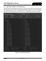
5.9.
INTELLIGAIN CONFIGURATION (+IG OPTION ONLY)
IntelliGain is a technology developed by Evertz to control the loudness of audio programs on the fly.
More specifically, it calculates the perceived loudness of the input audio and modifies the audio to
ensure that the long-term average loudness level is at the target level. IntelliGain works with mono,
stereo and multi-channel audio per program and can handle up to 16 programs simultaneously. The
objective loudness calculation is based on ITU Recommendation (ITU-R BS.1770), “Algorithms to
measure audio program loudness and true-peak audio level”. This recommendation provides equations
for calculating loudness over mono, stereo and multi-channel audio programs. IntelliGain constantly
calculates audio program loudness. When the loudness is over the target level, it reduces the gain; and
when the loudness is below the target level, it increases the gain. The gain adjustment smoothness is
user-controllable by setting attack and release times.
The IntelliGain Configuration tab displays the top-level IntelliGain control interface. There are a number
of parameters that control both the intelligent leveler and the on-board dynamic processor (compressor,
expander, limiter). The IntelliGain 1 Programs and IntelliGain 2 Programs tabs allow the user to control
the behavior of the leveler and dynamic processor. The tabs also provide monitoring information for the
measurement of the input loudness.
For complete instructions on how to configure IntelliGain refer to the IntelliGain User Manual for the
most current instructions.
Figure 5-9 : IntelliGain Configuration Tab
Revision 1.0
Page 33
7700/7800 MultiFrame Manual
7847FSE 3G/HD/SD-SDI Advanced Frame Synchronizer with Embedded Audio
Figure 5-10 : IntelliGain 1 Programs Tab
Page 34
Revision 1.0
7700/7800 MultiFrame Manual
7847FSE 3G/HD/SD-SDI Advanced Frame Synchronizer with Embedded Audio
5.10.
INTELLIGAIN FAULT TRAPS (+IG OPTION ONLY)
The IntelliGain 1 and IntelliGain 2 Fault Traps tabs allow the user to configure traps and monitor the
trap statuses for IntelliGain related functions. To enable a particular trap, simply click the box located
beside each trap in the Trap Enable section so that a check mark appears. When a check mark is
present, the trap is enabled. When a check mark is not present, the trap is disabled.
If a parameter under the Trap Status section is green, then the trap is present. If the parameter is red,
then the trap is missing.
Figure 5-11 : IntelliGain 1 Fault Traps Tab
Revision 1.0
Page 35
7700/7800 MultiFrame Manual
7847FSE 3G/HD/SD-SDI Advanced Frame Synchronizer with Embedded Audio
5.11.
FAULT CONTROL (+2X1 OPTION ONLY)
The Fault Control tab contains two sections. The Video Faults section allows the user to set various
parameters used to define the thresholds for detecting faults in the video. The Audio Faults section
allows the user to define the thresholds for detecting faults in the audio. Both of these sections are used
together to define the conditions used for switching. Sections 5.11.1 to 5.11.9 describe the various
controls in detail.
Figure 5-12 : Fault Control Tab
5.11.1. Video Loss Duration
The Video Loss Duration control enables the user to set the number of frames of missing video (or
TRS/lock) that are detected before a video loss alarm is generated. The range of this control is 0 to 900
frames in 1 frame increments.
5.11.2. Black Duration
The Black Duration control enables the user to set the number of frames of black video that are
detected before a video black alarm is generated. The range of this control is 4 to 9996 frames in 1
frame increments.
5.11.3. Freeze Duration
The Freeze Duration control enables the user to set the number of frames of frozen video that are
detected before a video freeze alarm is generated. The range of this control is 1 to 2499 frames in 1
frame increments.
Page 36
Revision 1.0
7700/7800 MultiFrame Manual
7847FSE 3G/HD/SD-SDI Advanced Frame Synchronizer with Embedded Audio
5.11.4. Picture Noise Level
The Picture Noise Level control enables the user to set the approximate level of noise expected in the
video signal feed. This is used by the freeze detect feature to distinguish motion from background noise
on top of a video feed. The range of this control is 1 to 10 in single increments. As a guide, a value of 1
is digital freeze (no noise on top of frozen picture) and a value of 10 is approximately 40 dB SNR.
5.11.5. Audio Loss Duration
The Audio Loss Duration control enables the user to set the number of frames of missing audio that are
detected before an audio group loss alarm is generated. The range of this control is 0 to 300 frames in
1 frame increments.
5.11.6. Audio Over Level
The Audio Over Level control enables the user to set the level threshold for when an audio channel
over alarm is generated. The range of this control is -80 to 0 dBFS in 1 dBFS increments.
5.11.7. Audio Over Duration
The Audio Over Duration control enables the user to set the time that the audio must be over the Audio
Over Level before an audio channel over alarm is generated. The range of this control is 0.5 to 300.0 s
in 0.5 s increments.
5.11.8. Audio Silence Level
The Audio Silence Level control enables the user to set the level threshold for when an audio channel
silence alarm is generated. The range of this control is -80 to 0 dBFS in 1 dBFS increments.
5.11.9. Audio Silence Duration
The Audio Silence Duration control enables the user to set the time that the audio must be under the
Audio Silence Level before an audio channel silence alarm is generated. The range of this control is 0.5
to 300.0 s in 0.5 s increments.
Revision 1.0
Page 37
7700/7800 MultiFrame Manual
7847FSE 3G/HD/SD-SDI Advanced Frame Synchronizer with Embedded Audio
5.12.
INPUT FAULT CONTROL (+2X1 OPTION ONLY)
The Input Fault Control tab contains two sections for each of the inputs PGM In-A and PGM In-B. The
Fault Triggers and Fault Conditions sections are used together to allow the user to set the conditions
used to determine when an input is considered faulty. This information is used by the automatic
changeover to switch between the two inputs. Section 5.12.1 describes the various controls in detail.
Figure 5-13 : Input Fault Control Tab
Page 38
Revision 1.0
7700/7800 MultiFrame Manual
7847FSE 3G/HD/SD-SDI Advanced Frame Synchronizer with Embedded Audio
5.12.1. PGM In-A and PGM In-B Fault Triggers
The PGM In-A and PGM-In-B Fault Triggers sections allow the user to set conditions used to determine
if the input is healthy. This is then used by the auto changeover to determine if and when to switch
between the two inputs. These fault conditions are triggered based on the threshold and duration
settings configured in section 5.11. The controls pertaining to this function are as follows:
Fault Triggers
The Fault Triggers are a list of faults that can be enabled and disabled by checking the
associated checkbox beside the fault name. If checked, these faults are used to determine the
health of each respective input.
Logic
The Logic control enables the user to set the condition for how the faults for each input source
are used. The values for this control are OR and AND. The OR condition will consider the input
as faulty if any one of the faults are triggered. The AND condition will consider the input as faulty
only if all of the faults are triggered.
Fault Clear Duration
The Fault Clear Duration control enables the user to set the number of frames that an input is
fault free before the fault condition for the input is cleared. The range of this control is 1 to 254
frames in 1 frame increments.
Revision 1.0
Page 39
7700/7800 MultiFrame Manual
7847FSE 3G/HD/SD-SDI Advanced Frame Synchronizer with Embedded Audio
5.13.
FAULT TRAPS PGM (+2X1 OPTION ONLY)
The Fault Traps PGM In-A and Fault Traps PGM IN-B tabs allow the user to configure various traps
and monitor the trap statuses associated with the 2X1 switching function. To enable a particular trap,
simply click the box located beside each trap in the Trap Enable section so that a check mark appears.
When a check mark is present, the trap is enabled. When a check mark is not present, the trap is
disabled.
If a parameter under the Trap Status section is green, then the trap is present. If the parameter is red,
then the trap is missing.
Figure 5-14 : Fault Traps PGM In-A Tab
Page 40
Revision 1.0
7700/7800 MultiFrame Manual
7847FSE 3G/HD/SD-SDI Advanced Frame Synchronizer with Embedded Audio
5.14.
TTX (+TTX OPTION ONLY)
The TTX tab contains four sections that are used to define the behavior of the WST inserter. The Status
section provides information on the first two lines of WST that are detected by the card. The Config
section provides the user with controls to define the insertion location for WST. The Clear Down section
is used to define the parameters for using a clear down. The Dummy/Apology Caption section allows
the user to configure a default message used in the absence of WST. Sections 5.14.1 to 5.14.11
describe the various controls in detail.
Figure 5-15 : TTX Tab
5.14.1. WST Status
The WST Status section provides information regarding the status of the first and second WST lines.
For each line the user is presented with the Input Status, Input Line #, Output Status and Output Line #.
The values presented for the Input Status are ABSENT, PRESENT-OP42 and PRESENT-OP47. The
values presented for Output Status are Input Passed, Dummy Captions Inserted, Clear Down Inserted,
Apology Captions Inserted and Copied Packet from Packet 2.
Revision 1.0
Page 41
7700/7800 MultiFrame Manual
7847FSE 3G/HD/SD-SDI Advanced Frame Synchronizer with Embedded Audio
5.14.2. WST Processing/Passing
The WST Processing/Passing control enables the user to set whether WST is processed or not. The
values for this control are as follows:
Disable
WST is not passed.
Enable
WST is passed and processing is allowed.
5.14.3. WST Output Line in Frame
The WST 1st Output Line in Frame and WST 2nd Output Line in Frame controls enable the user to set
the output video line to insert the first and second WST lines respectively. If the Follow input once seen
radio button is selected then this control is disabled and the output line will be the same as the input
line. If the User selected ratio button is selected then this control is enabled with range 1 to 22 in 1 line
increments. The range will change depending on the input video standard.
5.14.4. Auto Clear Down
The Auto Clear Down control enables the user to automatically insert a clear down if no WST is
detected on the input. The values for this control are as follows:
Disable
A clear down cannot be inserted.
Enable
A clear down is automatically inserted.
5.14.5. Auto Clear Down Delay
The Auto Clear Down Delay control enables the user to set the number of seconds that WST is missing
before a clear down is inserted. The range of this control is 1 to 50 s in 1 s increments.
5.14.6. GPI Triggered Clear Down
The GPI Triggered Clear Down control enables the user to insert a clear down by using a GPI. The
values for this control are as follows:
Disable
A clear down cannot be inserted using a GPI.
GPI1-4
A clear down is inserted if the respective GPI is triggered.
5.14.7. Dummy Captions
The Dummy Captions control enables the user to insert a default dummy caption when no captions are
detected on the input. The apology caption takes precedence over the dummy caption when both are
enabled. The values for this control are as follows:
Off
Dummy caption is never inserted.
Auto
Dummy caption is inserted automatically when there are no
captions on the input.
Always
Dummy caption is always inserted regardless of the input.
Page 42
Revision 1.0
7700/7800 MultiFrame Manual
7847FSE 3G/HD/SD-SDI Advanced Frame Synchronizer with Embedded Audio
5.14.8. For Single Missing Line/Packet
The For Single Missing Line/Packet control enables the user to set the behavior when only one WST
line (OP-42) or packet (OP-47) is seen per frame instead of two. The values for this control are as
follows:
Do Nothing
Nothing is inserted.
Duplicate Last
Duplicate the data from the last received line/packet and insert it in
place of the missing one.
Insert Dummy
Insert the dummy caption.
5.14.9. Apology Caption
The Apology Captions control enables the user to insert an apology caption when no captions are
detected on the input. The apology caption takes precedence over the dummy caption when both are
enabled. The values for this control are as follows:
Off
Apology caption is never inserted.
Auto
Apology caption is inserted automatically when there are no
captions on the input.
Always
Apology caption is always inserted regardless of the input.
5.14.10. Apology Caption Delay
The Apology Caption Delay control enables the user to set the number of seconds that captions are
missing before an apology caption is inserted. The range of this control is 1 to 50 s in 1 s increments.
5.14.11. Apology Caption Text
The Apology Caption Text field enables the user to enter text for the apology caption that is inserted.
This field has a maximum length of 64 characters.
Revision 1.0
Page 43
7700/7800 MultiFrame Manual
7847FSE 3G/HD/SD-SDI Advanced Frame Synchronizer with Embedded Audio
5.15.
AUDIO/VIDEO TRAPS
The Audio/Video Traps tab allows the user to configure various traps and monitor the trap statuses. To
enable a particular trap, simply click the box located beside each trap in the Trap Enable section so that
a check mark appears. When a check mark is present, the trap is enabled. When a check mark is not
present, the trap is disabled.
If a parameter under the Trap Status section is green, then the trap is present. If the parameter is red,
then the trap is missing.
Figure 5-16 : Audio/Video Traps Tab
Page 44
Revision 1.0
7700/7800 MultiFrame Manual
7847FSE 3G/HD/SD-SDI Advanced Frame Synchronizer with Embedded Audio
6.
JUMPERS
Figure 6-1 provides the locations of the jumpers and LEDs on the 7847FSE board.
J7
MODULE
STATUS
Serial
Upgrade
Run
J2
OFF FRAME
J2
ON STATUS
Figure 6-1: Location of Jumpers – Top View
6.1.
SELECTING WHETHER LOCAL FAULTS WILL BE MONITORED BY THE GLOBAL FRAME
STATUS
FRAME STATUS: The FRAME STATUS jumper J2 is located near the rear of the board and close to
the white metal connector. The FRAME STATUS jumper determines whether local
faults (as shown by the Local Fault indicator) will be connected to the 7700FR-C or
7800FR frame's global status bus.
To monitor faults on this module with the frame status indicators (on the PS FRAME
STATUS LED's and on the Frame's Fault Tally output) install this jumper in the On
position. (Default)
When this jumper is installed in the Off position, local faults on this module will not be
monitored.
6.2.
CONFIGURING THE MODULE FOR FIRMWARE UPGRADES
Firmware updates can be performed using two methods. The first method is an Ethernet based up-load
of firmware using VistaLINK® PRO. The second method is a serial interface based up-load of firmware
which uses the on-card upgrade serial port.
UPGRADE:
The UPGRADE jumper (J2) is located on the top side of the main module near the
front of the card and is used when firmware upgrades are being performed on the
module. For normal operation it should be switched to the RUN position as shown in
the Figure 6-1 and Figure 6-2. See the Upgrading Firmware chapter in the front of the
manual binder for more information.
To upgrade the firmware in the module unit pull it out of the frame. Move Jumper J2
into the UPGRADE position. Install the Upgrade cable provided (located in the vinyl
pouch in the front of this manual) onto header J7 at the card edge. Re-install the
Revision 1.0
Page 45
7700/7800 MultiFrame Manual
7847FSE 3G/HD/SD-SDI Advanced Frame Synchronizer with Embedded Audio
module into the frame. Run the upgrade as described in the Upgrading Firmware
chapter. Once the upgrade is complete, remove the module from the frame, move J2
into the RUN position, remove the upgrade cable and re-install the module. The
module is now ready for normal operation.
6.3.
Data Bits = 8
Parity = None
Stop Bits= 1
Flow Control = None
SELECTING WHETHER THE GENLOCK REFERENCE INPUT IS TERMINATED
TERM:
6.4.
The Upgrade baud rate for the 7847FSE module is 115,200 baud. Additional serial
connection settings are as follows:
The micro DIP switch on the bottom of the board (near the connector) is used to
terminate the genlock loop input. When DIP Switch 1 is set to “ON”, the 75 ohm
terminating resistor is placed between the genlock input and ground. When DIP Switch
1 is set in the “OFF” position the genlock input will be high impedance. Leave DIP
SWITCH 2, 3 and 4 in the OFF position.
USING A SLOT BLOCKER
The 7847FSE module can be installed in either the 7700FR-C or the 7800FR frames. These modules
are designed to occupy one slot in the Evertz 7800FR frame and two slots in the 7700FR-C.
The 7847FSE module can fit into one slot in a 7800FR frame because the 7800FR allows modules to
consume more power on a per slot basis than the Evertz 7700FR-C. When a 7847FSE module is
installed in the 7700FR-C, the module must occupy 2 slots to ensure that the frame power is managed
properly. This is accomplished by installing a “Slot Blocker” on the bottom side of the board. If the “Slot
Blocker” is not installed on the card and the card is inserted into the 7700FR, the card will not power-up.
When installing the card in a 7800FR frame, the “Slot Blocker” may be removed and it will power-up
and operate normally. If the “Slot Blocker” remains installed and the card is inserted into the 7800FR
frame, the card will also power-up and operate normally.
Figure 6-2: Slot Blocker
Page 46
Revision 1.0
7700/7800 MultiFrame Manual
7847FSE 3G/HD/SD-SDI Advanced Frame Synchronizer with Embedded Audio
7.
VISTALINK® REMOTE MONITORING/CONTROL
7.1.
WHAT IS VISTALINK®?
VistaLINK® is Evertz’ remote monitoring and configuration platform which operates over an Ethernet
network using Simple Network Management Protocol (SNMP). SNMP is a standard computer network
protocol that enables different devices sharing the same network to communicate with each other.
VistaLINK® provides centralized alarm management, which monitors, reports, and logs all incoming
alarm events and dispatches alerts to all the VLPro Clients connected to the server. Card configuration
through VistaLINK® PRO can be performed on an individual or multi-card basis using simple copy and
paste routines, which reduces the time to configure each module separately. Finally, VistaLINK®
enables the user to configure devices in the network from a central station and receive feedback that
the configuration has been carried out.
There are 3 components of SNMP:
1. An SNMP manager, also known as a Network Management System (NMS), is a computer running
special software that communicates with the devices in the network. Evertz VL-Fiber demo Manager
graphical user interface (GUI), third party or custom manager software may be used to monitor and
control Evertz VistaLINK® enabled fiber optic products.
2. Managed devices, (such as 7707EO and 7707OE cards), each with a unique address (OID),
communicate with the NMS through an SNMP Agent. Evertz VistaLINK® enabled 7700 series
modules reside in the 3RU 7700FR-C MultiFrame and communicate with the manager via the
7700FC or 7800FC VistaLINK® frame controller modules, which serves as the Agent.
3. A virtual database, known as the Management Information Base (MIB), lists all the variables being
monitored, which both the Manager and Agent understand. Please contact Evertz for further
information about obtaining a copy of the MIB for interfacing to a third party Manager/NMS.
For more information on connecting and configuring the VistaLINK® network, see the 7700FC or
7800FC Frame Controller chapter.
7.2.
VISTALINK® PARAMETERS
All control and monitoring of the 7847FSE is done through the use of VistaLINK® so all control and
monitoring parameters described in section 5 are the same as the ones available through VistaLINK®.
Please refer to that section for more information.
Revision 1.0
Page 47
7700/7800 MultiFrame Manual
7847FSE 3G/HD/SD-SDI Advanced Frame Synchronizer with Embedded Audio
This page left intentionally blank
Page 48
Revision 1.0