1
Help
© Copyright 2011 Robert Bosch Engineering
and Business Solutions Limited
2 | BUSMASTER | TOC
Contents
Introduction..................................................................................................................... 7
What is new?....................................................................................................................9
Getting Started.............................................................................................................. 11
Operating Modes........................................................................................................... 14
Status Bar.......................................................................................................................15
General........................................................................................................................... 16
Configuration settings in a file........................................................................................................ 16
CAN................................................................................................................................ 17
Configuration...................................................................................................................................17
Baudrate...............................................................................................................................17
App Filter.............................................................................................................................20
Log and Replay....................................................................................................................22
Configure Replay.................................................................................................................25
Message Display..................................................................................................................26
Transmit Messages.............................................................................................................. 31
Node Simulation Configuration...........................................................................................36
Message Log....................................................................................................................................44
Replay..............................................................................................................................................45
Cyclic Mode........................................................................................................................ 45
Single Run Mode................................................................................................................. 46
Enable/Disable Filter....................................................................................................................... 47
Node Simulation Configuration.......................................................................................................48
Node Simulation Examples............................................................................................................. 50
Database Editor................................................................................................................................54
Message Window............................................................................................................................ 58
Signal Generation............................................................................................................................ 63
Signal Watch....................................................................................................................................66
Signal Graph.................................................................................................................................... 68
Trace Window................................................................................................................................. 77
Test Automation.............................................................................................................................. 77
Test Setup File..................................................................................................................... 78
Test Setup Editor................................................................................................................. 80
Test Suite Executor..............................................................................................................83
Network Statistics............................................................................................................................84
J1939................................................................................................................................................85
Connect and Disconnect.................................................................................................................. 93
Format Converters........................................................................................................................... 93
API Reference..................................................................................................................................97
STCAN_MSG Structure......................................................................................................97
API Listing.......................................................................................................................... 99
J1939 API Reference..................................................................................................................... 103
J1939 Structures................................................................................................................ 103
J1939 API Listing..............................................................................................................105
COM Interface...............................................................................................................................112
BUSMASTER COM interface.......................................................................................... 112
COM Interface API Listing............................................................................................... 114
Know About SubErrors................................................................................................................. 120
Diagnostics.................................................................................................................................... 121
Diagnostics Settings.......................................................................................................... 121
Diagnostics Main Window................................................................................................ 123
FlexRay.........................................................................................................................125
FlexRay Simulation in BUSMASTER.......................................................................................... 125
Cluster Configuration.................................................................................................................... 125
FlexRay Controller Configuration.................................................................................................127
BUSMASTER | TOC | 3
Transmit Messages........................................................................................................................ 128
FlexRay Message Window............................................................................................................132
LIN................................................................................................................................135
LIN Simulation in BUSMASTER.................................................................................................135
LIN Cluster Configuration.............................................................................................................135
LIN Schedule Table Configuration............................................................................................... 136
LIN Controller Configuration........................................................................................................138
Transmit Messages........................................................................................................................ 138
Connect and Disconnect................................................................................................................ 139
LIN Message Window...................................................................................................................140
Network Statistics..........................................................................................................................142
Signal Watch..................................................................................................................................143
Logging..........................................................................................................................................145
App Filter.......................................................................................................................................147
Message Display............................................................................................................................149
LIN Node Simulation.................................................................................................................... 154
Node Simulation Configuration.........................................................................................154
Function Editor.................................................................................................................. 157
Responding to Master Request.......................................................................................... 162
LIN API Reference............................................................................................................162
LIN Database Editor......................................................................................................................167
Introduction....................................................................................................................... 168
Overview........................................................................................................................... 168
Getting Started...................................................................................................................171
LDF Elements....................................................................................................................171
C Library Functions....................................................................................................193
Standard Library Functions........................................................................................................... 193
abs : integer absolute value (magnitude)........................................................................... 193
atexit : request execution of functions at program exit..................................................... 193
atof, atoff : string to double or float...................................................................................193
atoi, atol : string to integer.................................................................................................194
bsearch : binary search...................................................................................................... 194
calloc : allocate space for arrays........................................................................................195
div : divide two integers.................................................................................................... 195
ecvt,ecvtf,fcvt,fcvtf : double or float to string...................................................................195
gvcvt, gcvtf : format double or float as string................................................................... 196
ecvtbuf, fcvtbuf : double or float to string.........................................................................196
exit : end program execution............................................................................................. 196
getenv : look up environment variable.............................................................................. 197
labs : long integer absolute value...................................................................................... 197
ldiv : divide two long integers........................................................................................... 197
malloc, realloc, free : manage memory............................................................................. 198
mbtowc : minimal multibyte to wide char converter.........................................................198
qsort : sort an array............................................................................................................ 199
rand, srand : pseudo-random numbers...............................................................................199
strtod, strtodf : string to double or float.............................................................................199
strtol : string to long...........................................................................................................200
strtoul : string to unsigned long......................................................................................... 201
system : execute command string......................................................................................201
wctomb : minimal wide char to multibyte converter.........................................................202
Character Type Macros and Functions..........................................................................................202
isalnum : alphanumeric character predicate...................................................................... 202
isalpha : alphabetic character predicate............................................................................. 202
isascii : ASCII character predicate.................................................................................... 203
iscntrl : control character predicate................................................................................... 203
isdigit : decimal digit predicate......................................................................................... 203
islower : lower-case character predicate............................................................................203
isprint, isgraph : printable character predicate...................................................................204
ispunct : punctuation character predicate.......................................................................... 204
isspace : whitespace character predicate........................................................................... 204
4 | BUSMASTER | TOC
isupper : uppercase character predicate............................................................................. 205
isxdigit : hexadecimal digit predicate................................................................................205
toascii : force integers to ASCII range.............................................................................. 205
tolower : translate characters to lower case....................................................................... 206
toupper : translate characters to upper case....................................................................... 206
I/O Functions................................................................................................................................. 206
clearerr : clear file or stream error indicator......................................................................207
fclose : close a file............................................................................................................. 207
fdopen : turn open file into a stream..................................................................................207
feof : test for end of file..................................................................................................... 207
ferror : test whether read/write error has occurred............................................................ 208
fflush : flush buffered file output.......................................................................................208
fgetc : get a character from a file or stream....................................................................... 208
fgetpos : record position in a stream or file....................................................................... 209
fgets : get character string from a file or stream................................................................209
fiprintf : format output to file (integer only)......................................................................209
fopen : open a file.............................................................................................................. 209
fputc : write a character on a stream or file....................................................................... 210
fputs : write a character string in a file or stream.............................................................. 211
fread : read array elements from a file...............................................................................211
freopen : open a file using an existing file descriptor........................................................211
fseek : set file position....................................................................................................... 211
fsetpos : restore position of a stream or file.......................................................................212
ftell : return position in a stream or file............................................................................. 212
fwrite : write array elements..............................................................................................213
getc : read a character (macro).......................................................................................... 213
getchar : read a character (macro)..................................................................................... 213
gets : get character string (obsolete, use fgets instead)......................................................214
iprintf : write formatted output (integer only)................................................................... 214
mktemp, mkstemp : generate unused file name................................................................ 214
perror : print an error message on standard error.............................................................. 215
printf, fprintf, sprintf : format output.................................................................................215
putc : write a character (macro)......................................................................................... 217
putchar : write a character (macro)....................................................................................217
puts : write a character string.............................................................................................217
remove : delete a file's name..............................................................................................218
rename : rename a file....................................................................................................... 218
rewind : reinitialize a file or stream...................................................................................218
scanf, fscanf, sscanf : scan and format input..................................................................... 219
setbuf : specify full buffering for a file or stream..............................................................221
setvbuf : specify file or stream buffering...........................................................................221
siprintf : write formatted output (integer only)..................................................................222
tmpfile : create a temporary file........................................................................................ 222
tmpnam, tempnam : name for a temporary file................................................................. 222
vprintf, vfprintf, vsprintf : format argument list................................................................223
String and Memory Functions....................................................................................................... 223
bcmp : compare two memory areas...................................................................................223
bcopy : copy memory regions........................................................................................... 224
bzero : initialize memory to zero.......................................................................................224
index : search for character in string................................................................................. 224
memchr : find character in memory.................................................................................. 224
memcmp : compare two memory areas.............................................................................225
memcpy : copy memory regions....................................................................................... 225
memmove : move possibly overlapping memory..............................................................225
memset : set an area of memory........................................................................................ 225
rindex : reverse search for character in string....................................................................226
strcat : concatenate strings.................................................................................................226
strchr : search for character in string................................................................................. 226
strcmp : character string compare......................................................................................226
strcoll : locale specific character string compare...............................................................227
BUSMASTER | TOC | 5
strcpy : copy string............................................................................................................ 227
strcspn : count chars not in string...................................................................................... 227
strerror : convert error number to string............................................................................ 227
strlen : character string length........................................................................................... 229
strlwr : force string to lower case...................................................................................... 229
strncat : concatenate strings...............................................................................................230
strncmp : character string compare....................................................................................230
strncpy : counted copy string.............................................................................................230
strpbrk : find chars in string...............................................................................................230
strrchr : reverse search for character in string................................................................... 231
strspn : find initial match................................................................................................... 231
strstr : find string segment................................................................................................. 231
strtok : get next token from a string...................................................................................232
strupr : force string to uppercase....................................................................................... 232
strxfrm : transform string...................................................................................................232
Time Functions.............................................................................................................................. 233
asctime : format time as string...........................................................................................233
clock : cumulative processor time..................................................................................... 233
ctime : convert time to local and format as string............................................................. 234
difftime : subtract two times..............................................................................................234
gmtime : convert time to UTC traditional form................................................................ 234
localtime : convert time to local representation.................................................................235
mktime : convert time to arithmetic representation...........................................................235
strftime : flexible calendar time formatter.........................................................................235
time : get current calendar time (as single number).......................................................... 236
C Math Library Functions............................................................................................................. 236
acos, acosf : arc cosine...................................................................................................... 236
acosh, acoshf : inverse hyperbolic cosine..........................................................................237
asin, asinf : arc sine............................................................................................................237
asinh, asinhf : inverse hyperbolic sine...............................................................................237
atan, atanf : arc tangent......................................................................................................238
atan2, atan2f : arc tangent of y/x....................................................................................... 238
atanh, atanhf : inverse hyperbolic tangent......................................................................... 238
jN,jNf,yN,yNf : Bessel functions...................................................................................... 238
cbrt, cbrtf : cube root......................................................................................................... 239
copysign, copysignf : sign of y, magnitude of x................................................................239
cosh, coshf : hyperbolic cosine..........................................................................................239
erf, erff, erfc, erfcf : error function.................................................................................... 240
exp, expf : exponential.......................................................................................................240
expm1, expm1f : exponential minus 1...............................................................................240
fabs, fabsf : absolute value (magnitude)............................................................................241
floor, floorf, ceil, ceilf : floor and ceiling..........................................................................241
fmod, fmodf : floating-point remainder (modulo).............................................................241
frexp, frexpf : split floating-point number.........................................................................241
gamma, gammaf, lgamma, lgammaf, gamma_r, gammaf_r, lgamma_r, lgammaf_r........ 242
hypot, hypotf : distance from origin.................................................................................. 242
ilogb, ilogbf : get exponent of floating point number........................................................243
infinity, infinityf : representation of infinity..................................................................... 243
isnan,isnanf,isinf,isinff,finite,finitef : test for exceptional numbers..................................243
ldexp, ldexpf : load exponent............................................................................................ 244
log, logf : natural logarithms............................................................................................. 244
log10, log10f : base 10 logarithms.................................................................................... 244
log1p, log1pf : log of 1 + x................................................................................................244
matherr : modifiable math error handler............................................................................245
modf, modff : split fractional and integer parts................................................................. 246
nan, nanf : representation of infinity................................................................................. 246
nextafter, nextafterf : get next number.............................................................................. 246
pow, powf : x to the power y............................................................................................. 246
rint, rintf, remainder, remainderf : round and remainder...................................................247
scalbn, scalbnf : scale by integer....................................................................................... 247
6 | BUSMASTER | TOC
sqrt, sqrtf : positive square root......................................................................................... 247
sin, sinf, cos, cosf : sine or cosine..................................................................................... 248
sinh, sinhf : hyperbolic sine...............................................................................................248
tan, tanf : tangent............................................................................................................... 248
tanh, tanhf : hyperbolic tangent......................................................................................... 248
Miscellaneous Macros and Functions............................................................................................249
unctrl : translate characters to upper case.......................................................................... 249
Variable Argument Lists................................................................................................... 249
Copyright....................................................................................................................................... 251
Hot Keys....................................................................................................................... 252
Frequently Asked Questions...................................................................................... 253
Additional Installation................................................................................................ 256
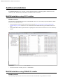
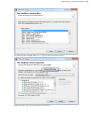
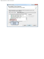
MinGW Installation using GCC Installer......................................................................................256
MinGW Installation using TDM-GCC Installer............................................................................256
BUSMASTER | Introduction | 7
Introduction
BUSMASTER Overview
BUSMASTER is a user friendly and cost effective testing and development tool for CAN bus systems that runs
on Windows 2000, Windows XP and Windows 7. It helps in monitoring, analyzing and simulation of CAN
messages the bus. Using its powerful functions and user-programmability one can simulate CAN system of any
complexity.
Additionally it provides options to analyze data bytes in raw data format or logical/physical data format and
signals can be monitored separately. These two functionality is achieved using a message database. An in-built
database editor is provided to create message databases.
The user can simulate a CAN node’s behavior or enhance the functionality of BUSMASTER. This is done by
means of 32 bit windows Dynamic Link Library (DLL). A DLL containing BUSMASTER interface can be
loaded dynamically to simulate the node’s behavior. An in-built Function editor is provided to write program in
ANSI C and build a DLL. Once DLL is generated, it can be loaded and used dynamically.
There are many others features that can be used without any programming. The key such features are
•
•
•
•
•
•
•
•
•
Display of messages,
Message information and Interpretation,
Filters,
Logging,
Replaying logged messages,
Network statistics,
Different time stamping,
Interactive transmission of message blocks,
Signal watch etc.
To facilitate the user programming a comprehensive set of APIs and event handlers are provided.
Key Features
•
•
•
•
•
•
•
•
•
•
•
•
Using USB port multiple USB CAN hardware can be connected and monitored with multiple instances of
BUSMASTER application.
It operates in Active mode. In active mode the tool influences the bus. In passive mode the tool does not have
any influence on the bus.
It supports CAN 2.0A and 2.0B protocol.
The messages can be displayed in decimal or hexadecimal format.
There are three different time stampings namely system time, relative time and absolute time mode. The
absolute time is the time from when tool is connected to CAN bus. The relative time is time between two
consecutive messages if the display is configured in scroll mode. In overwrite mode it is the time difference
between two messages of same ID. Time stamping is done at CAN driver level. The system time is PCs real
time value.
User can log messages to a file and replay the logged file. The time stamping mode can be also be configured
in System, Relative and Absolute mode during logging. The replay can be selectively done for transmitted,
received and all messages. More then one logging session with same time stamping can be combined in a
single replay session. The replay can also be configured in a cyclic manner with different time delay.
The message filtering can be done through Software, hardware or both. Software filter works at application
level while hardware filter works at CAN controller level.
It supports transmission of message blocks in single shot or periodic mode with time/key trigger.
It can display messages and error frames on CAN bus.
User can configure acceptance filter, baud rate and warning limit. Warning limit is not supported currently by
BUSMASTER with USB interface.
Message display can be configured in different colours. Different colours can be assigned to different message
IDs. Message display entries and the display update rate can be configured.
It provides a message database editor for creating & editing of messages and its signals.
8 | BUSMASTER | Introduction
•
•
•
•
•
•
The signals of message can be interpreted. It can be interpreted in a separate window or on message display
window.
Signals alone can be monitored separately with time stamping.
It provides programming facility through Function editor. The event-based programming is done using ANSI
C language. The user can use all windows provided APIs and any third party LIB/DLL/API files.
It supports all bit rates up to 1 MBPS.
User can analyse of bus statistics.
User preferences can be saved or loaded. The last saved user preferences are loaded automatically at the start
of application.
BUSMASTER | What is new? | 9
What is new?
2.6.4
Following features are added:
•
•
•
•
Advanced log file settings
Replay optimization for CAN
Node Simulation UI Improvement
Toolbar cleanup
2.6.3
Following features are added:
•
•
Support for LIN Kvaser
Bug Fixes
2.6.2
Following features are added:
•
Bug Fixes
2.6.1
Following features are added:
•
•
Support for FlexRay GIGATRONIK flex-i Controller.
Bug Fixes
2.6.0
Following features are added:
•
•
LIN Database editor (LDF)
Introduction of CMake for solution/project file generation
2.5.0
Following features are added:
•
•
BLF to LOG Conversion
Bug Fixes
2.4.0
Following features are added:
•
•
•
•
•
•
LIN PEAK device support
LIN Master mode
LIN Status message reporting
ISO-TP over CAN support
UDS support
Bug Fixes
2.3.0
Following features are added:
•
•
•
•
•
•
LIN Statistics window
LIN Signal watch
LIN Filters
LIN Message window configuration
LIN Diagnostic ID support (3C and 3D)
FlexRay ETAS BOA support for BOA 2.0 AND BOA 1.4
10 | BUSMASTER | What is new?
•
Bug Fixes
2.2.0
Following features are added:
•
•
•
•
Support for LIN ETAS BOA
Support for LIN logging
Support for BOA 2.0 for CAN and CANFD
Bug Fixes
2.1.0
LIN support added for slave node functionality. The tool can be used to respond back to master requests. It
supports the following features :
•
•
•
•
•
•
Support for LIN v1.3 and v2.0
Added LIN support for Vector XL library
LDF importing for cluster configuration and message interpretation
Modified Tx Window for DB and Non-DB frame configuration and data updation
Message Window with Error information and interpretation
Node Simulation for slave mode with message, timer, key and error handlers
2.0.0
Added Support For Following CAN Controllers:
•
ETAS ISOLAR EVE CAN
Added FlexRay Support For Following Controllers:
•
ETAS BOA
Added following FlexRay Modules:
•
•
FIBEX Import support for 2.0,3.0
Message Window
•
Transmit Window
Added LIN Support for Following Controllers
•
ETAS ISOLAR EVE LIN
Added Following LIN Modules:
•
Message window
•
Transmit Window
1.9.0
Support to following hardware interfaces are added:
•
•
•
•
NSI interface
i-View Interface
Development Environment IDE is migrated to Visual Studio 2012
Visual Studio Redistributable Package is expected by the installer script. Please refer development
environment for more information
BUSMASTER | Getting Started | 11
Getting Started
If you are using BUSMASTER application for the first time then the following section will help you to get
familiarized with the features of this tool. For this we will operate the BUSMASTER in self-reception mode i.e.
the BUSMASTER tool will be the sender and receiver of CAN messages.
Initial Setup
•
•
•
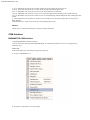
Call BUSMASTER.exe by double clicking the appropriate icon in the BUSMASTER program group.
The tool will only work with Active mode. Make sure that the USB hardware is connected to the PC and CAN
bus.
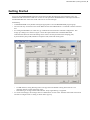
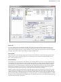
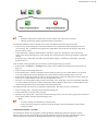
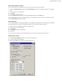
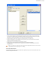
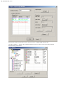
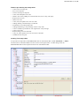
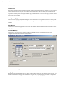
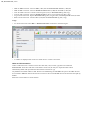
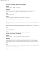
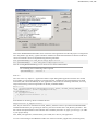
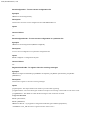
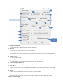
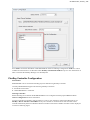
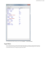
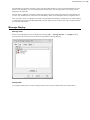
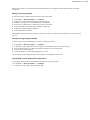
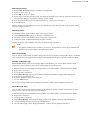
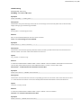
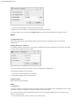
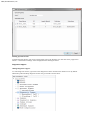
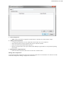
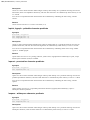
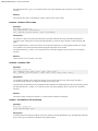
For setting the Baud Rate (a.k.a. Bit rate), go to Hardware menu and select Channel Configuration. This
brings up a dialog box as shown in figure 1. Enter the required baud rate in the Baud Rate field.
Other than the baud rate values this dialog can be used to set other parameters like sampling point,
Synchronization jump width, Hardware acceptance code, mask and warning limit.
•
•
In USB interface, setting Warning limit is not supported. The default warning limit value 96 is set
internally and user cannot change this value.
• Dual filtering is not supported in USB interface. Only single filtering is supported.
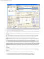
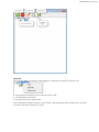
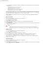
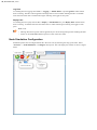
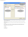
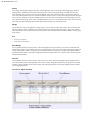
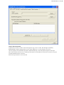
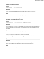
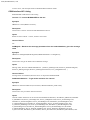
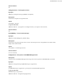
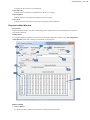
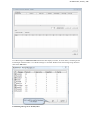
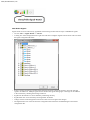
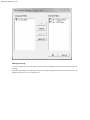
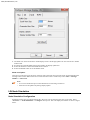
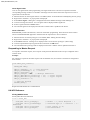
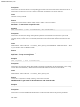
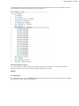
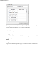
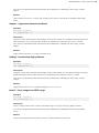
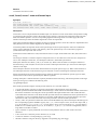
To send CAN messages, the messages has to be defined first. For this select Transmit menu under CAN menu
and select Configure menu. A dialog as shown below pops up.
12 | BUSMASTER | Getting Started
•
•
You can add a total of 32 Message Blocks having trigger condition either as “On Key” or “On Time” or both.
Each block of message can have a total of 64 messages.
You can activate any message block selectively for transmission by selecting a check box in Message Blocks
list.
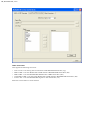
Message can be added that are not in the database as well as in the database. For details about this refer Transmit
Message(s)
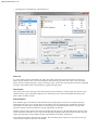
From the same dialog box one can select the time interval between two consecutive messages by entering the
delay value in milliseconds in the Interval box. The Key box is used to enter key value for key trigger. The
transmission can be configured as one shot or cyclic by selecting or deselecting the item Monoshot.
Close the dialog by clicking on OK button. You can use Apply button to save the changes without closing the
dialog.
User can also select the message from the list and transmit over the CAN bus by using Send button or by right
click in the list and selecting the Send menu. Message blocks and messages in blocks can be added/deleted by
selecting the menus. The pop up menu is displayed when user right clicks the corresponding list.
The message details can be modified even the transmission is in progress. Message data can be directly modified
by changing the data byte values or the signal values. Signal values can be given as raw value or physical value.
In all these cases all other values will be updated accordingly. You can modify the message details and select
Apply or OK button to reflect the changes for transmission. During transmission you can’t modify the details of
message block which is active. But you can add a new block or change the message block details for block, which
is not active.
On selection of start transmission only those blocks which is active having at least one message frame will be
transmitted. Also if the trigger is selected as On Key then the transmission will start when the corresponding key
is pressed.
Now the messages to be transmitted have been configured and it’s ready to be transmitted.
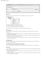
•
•
Select the Connect menu from the CAN menu option. This initializes the CAN controller.
To initiate the transmission of the messages go to the menu CAN --> Transmit --> Enable.
BUSMASTER | Getting Started | 13
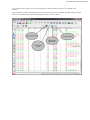
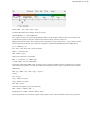
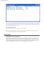
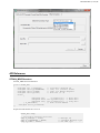
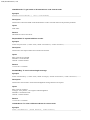
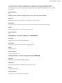
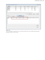
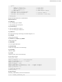
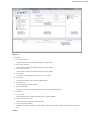
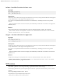
A cross mark on the message icon in the Tx Message list indicates that the message is not available in the
database.
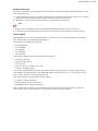
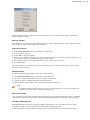
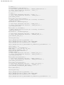
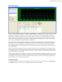
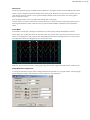
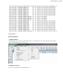
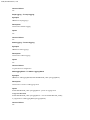
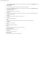
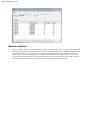
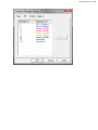
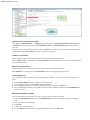
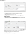
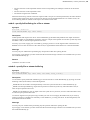
If the installation is proper and working then you should be able to see the configured messages being transmitted
and receive simultaneously in the Message display window as shown in below
14 | BUSMASTER | Operating Modes
Operating Modes
The BUSMASTER can be operated in Active mode
•
•
Active: In this mode the controller will participate in the bus activity i.e. it will generate acknowledgement
signal, error signals etc on reception of message and also will be able to transmit messages.
Passive - Currently this mode is disabled.
Any one of the above mentioned modes can be selected from the menu Hardware --> Driver Mode.
By default BUSMASTER will be in Active mode.
BUSMASTER | Status Bar | 15
Status Bar
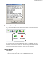
The status bar gives the following information
•
•
•
The first pane shows the loaded configuration file path.
The second pane displays the data logging status for CAN and J1939
The extreme right pane indicates the hardware selected, baud rate and the number of channels supported by
the application.
Note:
•
Error Counters values and controller status are displayed in Network Statics window.
16 | BUSMASTER | General
General
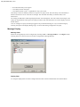
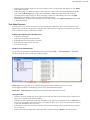
Configuration settings in a file
User can save your preferences of the tool into ".cfx" file. The last loaded configuration file will be loaded
automatically when the tool is run for the next session. If the configuration file is not found then, the application
will load the default configuration settings and the status of the loaded configuration filename will be shown on
the status bar.
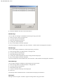
Creating New Configuration file
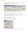
1. Select File --> New menu option. This will invoke file Save dialog box.
2. Enter the new configuration file name. And select Save button. The new configuration file will be loaded and
the same filename can be seen on the status bar.
Loading a Configuration File
1. Select File --> Load... menu option. This will invoke file Open dialog box.
2. Select the configuration file name. And select Open button. The selected configuration file will be loaded and
the loaded configuration file will be displayed in the status bar. The same configuration file will be displayed
on the top of MRU configuration file list ( File > Recent Configuration ).
3. Selecting a configuration file name from the MRU list will also do loading of the configuration file. If load is
successful then the same configuration file will be displayed on the top of MRU configuration file list.
Note:
•
While loading BUSMASTER with parallel port interface created configuration file in to USB
interface, checks have been made to find unsupported options. If anything found user will be informed
about that and BUSMASTER will changes those values to default internally. These changes will not
be saved unless the user selects File Configuration Save. Configuration file created in BUSMASTER
with USB interface can be loaded in to BUSMASTER with Parallel port interface.
Saving a configuration file
1. Select File --> Save menu option. This will invoke File Save dialog box.
2. Select the configuration file name. And select Save button.
3. The selected configuration file will be saved. The same configuration file will be displayed on the top of
MRU configuration file list ( File > Recent Configuration ).
Saving a configuration file with new name
1. Select File --> Save As menu option. This will invoke File Save As dialog box.
2. Enter new configuration file name. And select Save button. The selected configuration file will be saved.
If the loaded configuration file is changed during the usage of the tool, a save confirmation message is displayed
to the user before closing the application.
BUSMASTER | CAN | 17
CAN
Introduction
Configuration
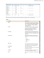
BUSMASTER has provision for configuring the following properties
•
•
•
•
•
•
•
•
•
Baudrate: By default the tool is configured to operate at 100kbps. This can be changed to any valid value
between 5 kbps and 1000 kbps.
Acceptance Filter: To increase the response of the tool at very high messages rate one can set the acceptance
filter. The controller filters the messages based on the values set for acceptance code and mask. This filtering
is faster than the software filter (App filters).
Warning Limit: One can monitor the condition of the network by setting a warning limit value. The user will
be notified when either one of the error counter (Tx & Rx) exceeds the warning limit. By default this value
is set to 96. The valid range is from 1 to 127. In USB interface setting warning limit is not supported and it is
internally set to 96.
Message Display: Every Message can be assigned a user defined color and text. The text associated with
the message will be displayed in the selected color along with its data in the message display window
whenever that message is transmitted or received. By default all the messages received are displayed in black
color. Display entries can be configured. This is the number of entries that the display will show. When the
messages received exceeds this count Display will scroll to show the latest entries. The display update rate can
also be configured. This will be used to refresh the display periodically.
App Filters: You can opt to view and log messages of your choice. Message filters provide this facility. Filters
can be applied to message display window, filters and / or message log. The filter list is configurable from
CAN --> Filter Configuration menu.
Message Logging: You can select a file to log all the transmitted & received messages. The start of logging
can also be triggered on reception of specific message name or message ID. You can configure a logging
session for different time stamping mode as well as Hex/Decimal format. You can also select to append or
overwrite an existing log file.
Message Replay: The messages that are logged to a file can be replayed. The replay can be configured by
choosing replay type, time delay and replay file name. You can explicitly specify the delay required between
messages or between cycles wherever applicable.
Transmit Message: You can configure/define messages that are to be sent on CAN bus. The configured
messages can be database messages or undefined messages (Undefined messages are those messages that are
not available in the database). Further the messages to be sent can be define as standard, extended messages or
as a RTR message.
Simulated Systems: Simulated systems can be configured under CAN Bus consisting of multiple nodes, each
representing a dll. Multiple user programs can be built as dlls and loaded. The configured simulated systems
can be saved and used across sessions.
The entire above-mentioned configuration except message replay is saved across sessions.
Refer the respective sections for more details
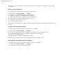
Baudrate
While defining a baud rate the number of samples/bit value can also be defined. For a selected baud rate a set of
all possible combinations of CNF0, CNF1 and CNF2 values will be listed. From this you can select any one set.
The selected combination of CNF0, CNF1 and CNF2 values will be used to initialize the CAN controller. The
baud rate can be changed by the method mentioned below.
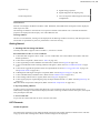
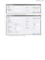
•
•
•
•
•
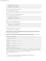
Select Hardware --> Channel Configuration.
Configure CAN Controller dialog box will be displayed as shown below.
Enter the required Baud rate.
If required select the Number of Sample/Bit.
Specific values for propagation delay and SJW can be selected too. Default selection for them is ALL.
18 | BUSMASTER | CAN
•
If the default value is not appropriate for the application then the required CNF0, CNF1 and CNF2 value can
be selected by selecting an entry from in the list.
Other fields like BRP, Sampling Point, SJW and NBT are dependent on CNF0, CNF1 and CNF2 values. On
clicking the "OK" button the controller will be initialized with the selected baud rate.
For more details on bit values of CNF0, CNF1 and CNF2 and the calculation of baud rate refer the section Bit
Time Calculation.
Note: For MH Tiny CAN, either Bit Rate or BTR will be considered. If Bit Rate value is available BTR
will be discarded.
Bit Timing Calculation
Abbreviations used:
•
•
•
•
•
•
•
•
•
•
•
tNBT - Nominal CAN Bit time
tsyn - Syncronization segment
PD - Propagation delay
tseg1 - Time segment 1
tseg2 - Time segment 2
tq - Time quantum
BRP - Baud rate prescaler
fsys - Controller system clock
fclk - Clock Frequency
NBT - Number of tq in tNBT
tPD - Propagation Delay time
The CAN protocol supports bit rates in the range of 1Kbps and 1000Kbps. Each node has its own clock generator
and oscillator.
Configuring the bit timing parameters for each node can facilitate a common bit rate on the bus.
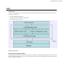
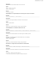
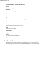
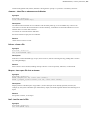
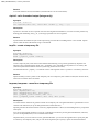
The Nominal CAN Bit Time (NBT) divided into four segments as shown below.
BUSMASTER | CAN | 19
Hence, tNBT = tsyn + tPD + tseg1 + tseg2
The Nominal Bit Rate is the number of bits per second.
Nominal Bit Rate = 1 / Nominal Bit Time
Each segment consists of a specific programmable number of time quantum, which is basic unit of bit time. The
synchronization segment is that part of the bit time where the edges of the CAN bus level.
Mapping between fsys and tq: The controller needs to regulate its system clock period (1 / fsys) in order to realise
the time quantum (tq) desired. The coefficient of regulation is defined as Baud Rate Prescaler (BRP). Hence,
tq = 2 * (BRP/ fsys ) (I)
fsys = fclk / 2 (II), where fclk is Clock Frequency
tNBT = 1 / baud rate (III)
NBT = tNBT / tq (IV)
Hence from equation (I), (II) and (III)
NBT = ( 1 / baud rate ) / (4 x BRP/ fclk)
=> NBT x BRP = fclk / (4 X Baud Rate)
The product value NBT x BRP will be an integer value. Appropriate baud rate will be calculated to get an integer
value for the above product. This will ensure that Clock Frequency remains same for a particular CAN controller.
Additionally,
NBT x tq = tNBT = tsyn + tPD + tseg1 + tseg2 (V)
Clearly,
tsyn = tq (VI)
tseg1 = TSEG1 x tq (VII)
tseg2 = TSEG2 x tq (VIII)
tPD = PD x tq (IX)
Therefore from equation (VI), (VII) and (VIII).
NBT = TSEG1 + TSEG2 + PD + 1.
Sampling Point = ((NBT - TSEG2) / NBT) x 100 %.
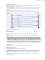
The neoVI hardware consist of three registers namely CNF1, CNF2, CNF3 the details of which are given below:
20 | BUSMASTER | CAN
SAM (Sampling) = 0 or 1 (1 or 3)
SJW = 2 x SJW1 + SJW0 + 1
BRP = 32 x BRP5 + 16 x BRP4 + 8 x BRP3 + 4 x BRP2 + 2 x BRP1 + BRP0 + 1
TSEG1 = 4 x TSEG1.2 + 2 x TSEG1.1 + TSEG1.0 + 1
TSEG2 = 4 x TSEG2.2 + 2 x TSEG2.1 + TSEG2.0 + 1
FLAG = 0 or 1 ( “TSEG2 Ignored” or “TSEG2 Considered”)
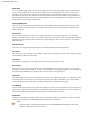
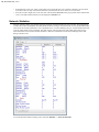
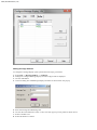
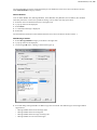
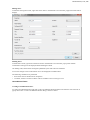
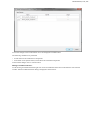
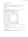
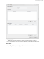
App Filter
User can configure filter list by choosing messages to be filtered.To configure the filter list, follow the steps given
below
•
•
Select CAN --> Filter Configuration.
The dialog box specified below will be displayed.
BUSMASTER | CAN | 21
Filter List
It is a list of filters that are identified by the name. The name of the filter should be unique and can have any
kind of special characters also. The second parameter tells about the type of the filter, pass or stop. Pass filter
allows only the configure message or range of message to pass. On the other size stop filter blocks the configured
messages. These filters shall be used in display, logging and replay filters.
Filter Details
This section shows list of message names, ID and range along with ID type, message frame type, direction and
channel number. Type is denoted by different icons. Selecting an entry from the list updates the details of the
filter in Filter Attributes section.
Filter Attributes
Filter attributes gives more details of selected filter entry. Message Name or ID in case of single id filtering and
message ID range in case of range filter will be update. ID type will give whether the ID is standard or extended
type. If ID type is "All" then ID type will be ignored. Frame type will show whether the message is of remote
transmit request or not. If this field shows all then frame type will be ignored. Direction field will show whether
the message is transmitted or received. If it is all then direction will be ignored. Channel filed associates the
message with particular channel. Channel all makes the message independent of channels.
Database message names shall be selected from the Message ID combo box. Message ID shall be directly typed
in this combo box. If the filter is for a range of messages then the Range radio button shall be selected. This will
enable range edit boxes. Message ID type gives information about the ID or message name. For database message
this field will be automatically updated. But user can change the type to override the database definition. To make
the filter to work for both standard and extended type user shall select the ID type as All. Other attributes shall be
selected based on the filter requirements.
22 | BUSMASTER | CAN
Event radio button shall be selected for Event filter. This will enable Event combo box, from which event type
can be selected. Channel combo box will enabled.
The Add button in the Filter Attributes section will add configured filter in to the selected named filter list. This
button will be disabled in case of invalid parameter entered by the user and appropriate error message will be
displayed in the status bar.
Once the filter is added in to the Filter List then the name of the filter will appear in the Filter Configuration List
to select. Any modification on these filter will immediately reflect in the all modules that are using these filters.
Filter list will be saved in configuration file and will be updated while loading a configuration file. While loading
a configuration file created with BUSMASTER 3.06.02.X.XXX version one filter entry will be created with the
previous filter information.
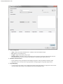
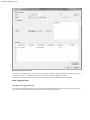
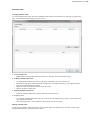
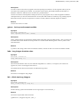
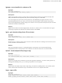
Log and Replay
Logging
User can configure log file setting using CAN --> Logging --> Configure menu. This will show log file
configuration dialog as shown below.
Log Files
User can add as many as log files in to the list of Log Files. This list will show the log files that are already
configured. To add a new Log file select Add button. This will add a log file with default file name. User can
change the file name using "..." button in the Log File Details section. The check box associated with the log
file will make the log file eligible for logging. If the check box is not checked logging will not happen to that
particular file.
BUSMASTER | CAN | 23
Log File Details
Log file details will give configuration of the selected log file. This will give info of log file path, time mode,
numeric mode, file mode, log triggers and log filter.
Log File Path
The file path text box will give the selected log file path. To change the path select "..." button. This will show
file selection dialog. On selection of a log file, the file path text box will be updated with selected file path.
Log File Size
Log file size is fixed to a limit of 50 MB. This limit is set as most of the editors will take lot of time to open if the
file size is large.
Time Mode
Logging of messages can be done in three different time modes. System time, Absolute time and Relative time
mode. In system time mode time stamping of message is done using real time clock of the system. In absolute
time mode the time stamping is done with respect the to the absolute timer that will be stated during connect. In
relative time mode the time stamping of a message is with respect to previously received message.
Reset Timestamp for every enable logging is provided. If this option is selected then the absolute time will be
reset whenever the logging is enabled.
Numeric Mode
This tells the numeric format of log file entries. It has two options Hex and Decimal. Message ID and data bytes
of a CAN message will use this as a base while format for logging.
File Mode
In Append file mode, log sessions will be appended at the end of the file. Each logging session will have its own
session header and footer. In Overwrite file mode the file will be overwritten for the first session. For consecutive
sessions the file name will be suffixed with an incrementing number and each session will be logged in new files.
The log file name will be incremented every-time when you stop the logging process.
If already log files are created in the previous session and if a new session is started, then the log files created
already will be overwritten in both overwrite and append mode. In this case, the successive files already created
in the previous session will contain old session data.
Logging Indication
Recording or logging is indicated in the status bar for both CAN and J1939. When the logging is enabled and data
is logged in to the file, an icon will be shown in the status bar with glowing on and glowing off continuously till
the logging is stopped. When the logging is stopped then icon will be disabled.
Example
If the log file name is xyz.log for the first time, then for the next time the log file name will
be xyz0.log.
Similarly, if the log file name is xyzn.log for the first time, where n – is any number, then for
the next time the log file name will be xyzm.log, where m = n + 1.
Create New Log File
Measurement - New Log file can be created for every Bus Connect. The new log file
will have a file name. Eg: BusmasterLogFile_CAN_Mn.log where 'n' is the count, and 'M'
indicates logging is 'Measurement' based.
Size - New Log file can be created with log file exceeding certain file size. The new log file
will have a file name. Eg: BusmasterLogFile_CAN_Sn.log where 'n' is the count, and 'S'
indicates logging is 'Size' based.
24 | BUSMASTER | CAN
Time - New Log file can be created for certain interval of time. The new log file will have
a file name. Eg: BusmasterLogFile_CAN_Tn.log where 'n' is the count, and 'T' indicates
logging is 'Time' based.
Comment
Comments can be inserted to the header of the log file.
Filters
Filters can be added for logging.
Enable/Disable Logging on Tool Connect/Disconnect
Logging can be enabled/Disable on Connect/Disconnect to CAN bus.
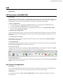
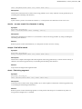
Message Log
CAN messages can be logged to a file for analysis. Log file name shall be selected as
described in section Logging.
To start message logging select Log Start or press the Tool Bar Button shown in the figure
below. The tool bar is toggle button. Clicking on the button or selecting the menu again will
stop logging. Once the logging has started, the messages received and transmitted will be
logged in to the file with time of message reception.
Note:
•
•
Logging will fail if the log file is not present in the specified location.
Logging status is stored in configuration file and logging will be started automatically
during application startup if it is enabled and saved in the configuration file.
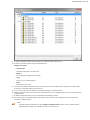
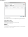
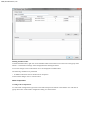
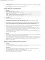
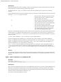
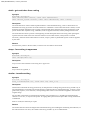
Replay
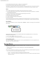
User can configure replay file setting using CAN --> Replay --> Configure menu. This will show replay file
configuration dialog as shown below.
BUSMASTER | CAN | 25
Replay Files
User can add as many as replay files in to the replay list. This list will show the replay files that are already
configured. To add a new Replay file select Add button. This will show replay file selection dialog. User can
select log files that are created using BUSMASTER. Once the user has selected a replay file, the file will be
added to the replay list. User can change the file "... " button in the Replay File Details section. The check box
associated with replay file will make the replay file eligible to run. If the check box is not checked then that
replay will not be used for replay.
Replay File Details
Replay file details will give configuration of the selected replay file. This will give info of replay file path, time
mode, replay mode, filters and Replay type.
Replay File Path
The file path text box will give the selected replay file path. To change the path select "..." button. This will show
file selection dialog. On selection of a log file, the file path text box will be updated with selected file path.
Replay Time Mode
Time mode or replay tells whether to use logged time for replay or to use user specified value. If user selects
Retain Delay option then the delay between messages will be calculated from the log file time stamping. If this
option is not checked then user can specify the delay between messages.
Replay Mode
Replay mode instructs whether the replay file has to be transmitted only once or cyclically. In cyclic mode,
messages will be transmitted periodically. User can specify the cycle delay which will be used in between cycles.
Where as in monoshot or once, the replay of messages will happen only once.
Replay messages option is provided to select the messages to tbe replayed. Tx, Rx and All messages options are
listed. All the messages in the log file will be replayed if All is selected. If Tx is selected then only the messages
logged with Tx flag in the log file will be replayed. If Rx is selected then only the messages logged with Rx flag
in the log file will be replayed.
Interactive Replay
In interactive replay mode, the log file content will be display as list of messages and user can navigate this
list and can transmit interested messages. User can step through replay messages, can skip messages, can start
message transmission continuously and can insert break points.
Non Interactive Replay
In non interactive mode, reply will start during tool connect and will be stopped during tool disconnect. In
case of cyclic mode the replay will continue till tool disconnect and in monoshot or once, all messages will be
transmitted only once and replay will start.
Configure Replay
Replay can be configured using the three parameters mentioned below
•
•
•
File Name
Mode
Time Delay
There are two modes of Replay
•
•
Single Run - The messages in the file will be replayed only once.
Cyclic - The messages in the file will be replayed cyclically.
The time delay can be set to control the delay between two consecutive messages and between two consecutive
replay of the same file.
The following field controls delays
26 | BUSMASTER | CAN
•
•
•
Recorded time delay in the log file
Time delay between messages.
Time delay between cycles – Applicable for only cyclic mode.
Time delay 1 and 2 are mutually exclusive irrespective of replay mode. This time delay is the time duration
between transmission of two consecutive messages. The minimum time delay (in milliseconds) is one
millisecond.
On clicking the OK button a Message Replay Window will be displayed. This will contain all messages in the
replay file. By default first message in the replay window will be selected. Please see section Replay a File for
further details.
User can configure to replay all message logged or only transmitted message or only received message by
selecting the option from Replay Message Type. It can be done during configuration of replay.
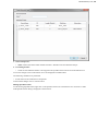
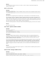
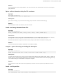
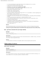
Message Display
Message Filter
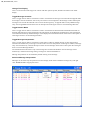
Filters for message display can be configured by selecting CAN --> Message Window --> Configure and by
selecting Filter tab. This will show list of filters configured for Message Display.
Display Filter
To configure display filter list select Configure button which will list available filters and selected filters.
BUSMASTER | CAN | 27
Message Coloring
User can configure the color with which the message will be displayed and associate a textual description to
message.
By default all messages are displayed in black color and the message ID itself as the associated text. For the
database message user can only edit the color.
28 | BUSMASTER | CAN
BUSMASTER | CAN | 29
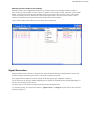
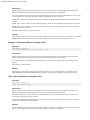
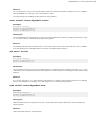
Adding message attribute
To configure a message display option, please follow the steps given below
1.
2.
3.
4.
Select CAN --> Message Window --> Configure
Dialog box Configure Message Display as in above figure will be displayed
Click on Add button
One more dialog box Add Message Display Attributes as shown below will pop up.
5.
6.
7.
8.
Enter the message ID and Message text
Click on the colored button to select a color, This click pops up a color palette as shown above.
Select a suitable color
Select OK button to confirm
30 | BUSMASTER | CAN
Subsequent reception / transmission of the message that has been configured will be displayed with associated
text & color.
Editing a message attribute
To edit the message attributes please follow the steps given below
1.
2.
3.
4.
5.
6.
7.
Select CAN --> Message Window --> Configure.
Dialog box Configure Message Display will be displayed.
Select the message entry to be edited from the message list.
Either click on Edit button or double click on the selected entry.
One more dialog box Edit Message Attributes will pop up.
Change the required Message attributes.
Select OK buttons to confirm.
Subsequent reception/transmission of the message that has been configured will be displayed with associated text
& color.
Deleting message display attribute
To delete an entry from the Message List follow the steps given below
1.
2.
3.
4.
5.
Select CAN --> Message Window --> Configure.
A dialog box will pop up. Select the message entry to be deleted from the message entry list.
Click on Remove button. A delete confirmation message box will be displayed.
Select Yes to confirm deletion.
Select OK button to confirm the modification of entries.
On subsequent reception/transmission, the message will be displayed in black color.
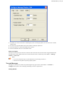
Display Buffer size & Update Rate configuration
To configure Append and overwrite buffer size, follow the steps given below
1. Select CAN --> Message Window --> Configure.
2. A dialog box will pop up. Select the Buffer page.
BUSMASTER | CAN | 31
3. The buffer size can be from 200 to 32500 display entries. The display update rate can be from 50 to 20000
milliseconds.
4. Set entries for Append buffer and overwrite buffer. Set display update rate.
5. Select OK button to confirm the modification of entries.
6. Select Set Default button to set the default values.
Show Last Option
This option can be used to set the focus of the list item to the latest item in Scroll mode. In append mode latest
message entries will be added at the end. To make the latest entries visible always select CAN --> Message
Window --> Show Last.
Note:
•
•
In overwrite mode this option will be disabled to avoid rolling of selection.
Selection will be update only during display update.
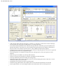
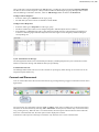
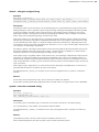
Transmit Messages
Messages can be send over CAN-bus by following the steps given below. Select CAN --> Transmit -->
Configure menu option. This will display the dialog as shown is figure below.
Getting Started
32 | BUSMASTER | CAN
•
•
•
•
•
•
•
•
•
•
•
•
Add a message block and select the trigger as “On Key” or “On Time” or both. Select a name of message
block and then enter appropriate message details in “Configure Message“.
If the field for Message ID/Name has a database message then DLC and frame type will be updated with
database information. The Signal List will be enabled with signals defined in the database. Signal Raw or
Physical values can be directly entered in this list. After validation the data will be updated.
Signal descriptor can be used to enter physical value. Double clicking the physical value cell of a signal that
got descriptor will show a list of signal descriptors.
If the message ID is not a database message enter DLC, Message bytes. In this case signal list will be
disabled.
RTR message can be added to by selecting RTR checkbox
If there is selection in the message list, changes will update the selected message.
Selecting Add Message button will add a new message entry.
Database messages can be directly entered by name or ID in the Message ID/ Name combo box or can be
selected from the combo box list items.
Signal Matrix will show the bit pattern of the data bytes.
Instead of using Update button, Auto Update option can be selected to dynamically save the data.
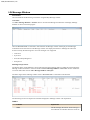
Select Update button to save the changes and press the toolbar button shown in the figure below.
BUSMASTER | CAN | 33
Note:
•
•
Start/Stop Transmission toolbar button will be enabled only if the tool is connected.
Message transmission shall be stopped with out tool disconnect.
The messages added in to the Tx message list can also be modified. Follow the steps given below.
•
•
•
Select an entry in the message list. The selected detail will be unpacked and will be displayed in the edit
controls below. If it is a database message then the signal details will be listed in the signal list with both
physical and raw values.
Any modification in Message Name/ID, DLC, Data bytes, signal raw and physical values will directly
reflect in the selected message entry in the message list. The signal matrix will also get updated to reflect the
changes.
Selecting Apply or OK button will reflect message details change in transmission immediately if message
transmission is on.
User can delete a message frame entry from the list by following the steps given below.
•
•
•
•
•
Select CAN --> Transmit --> Configure menu option. This will display the dialog box as shown below in
figure (a).
Select an entry in the message frame list.
Select Delete button. A delete confirmation will be displayed. Select Yes to confirm deletion. The selected
item will be deleted from the list. Multiple items can be selected to delete multiple items in one shot.
Select Delete All button to delete all entries in the message block. A delete all confirmation will be displayed.
Select Yes to confirm deletion. This will clear message block entries.
The other way of doing delete is Right click mouse button. This will display a pop-up menu Delete and Delete
All. Select Delete pop-up menu. A delete confirmation will be displayed. Select Yes to confirm deletion. The
selected message frame will be removed from the message frame list.
The added messages can be directly transmitted instantaneously. The steps to do this is listed below
•
•
•
Select a message entry or message entries from the message list.
Select Send button to transmit these messages.
The other way of doing this is right click on selected message entries. This will show a popup menu with Send
option. Select Send to transmit selected messages once.
Note:
•
•
To send a message tool should be in connected state.
If more then one message are selected to send, all messages will be transmitted one after another
without any delay.
Transmission Blocks - In Detail
The transmission blocks are segregated in to Message Blocks and Message frames that belong to a block.
Message blocks will have logical name and triggering attributes and list of messages. Message block name is
logical representation of the block. Message block attributes are triggering type and trigger value.
34 | BUSMASTER | CAN
Triggering Type
Two types of triggering are supported by BUSMASTER. These are timer and key triggering. In timer triggering
messages will be transferred periodically with the time delay mentioned in the trigger value. In case of key
triggering the message will be transmitted on press of the trigger character. These options will go along with the
repetition mode called Monoshot or Cyclic. In monoshot mode messages belong to a block will be transmitted
only once. After completing the cycle of transmission nothing will be transmitted. In cyclic mode message
transmission will happen cyclically. After completing one cycle of transmission, first message in the block will be
transmitted and so on.
In case of key triggering, if the mode is monoshot, messages in the block will be transmitted one after another for
each trigger key press. Once all messages are transmitted nothing will be transmitted. If the mode is cyclic after
completing one cycle the first message will be transmitted on press on the key again and this cycle will continue.
The special attribute All Message is used to generate heavy load condition. This is attribute is applicable only
for key triggering. If All Message is checked and the mode is monoshot, on press of the key all messages will
be transmitted once without any delay in between. If the mode is cyclic then all messages will be transmitted
continuously with out any delay in between. This can be stopped only be stopping the Tx message transmission.
Triggering Value
For timer triggering the triggering value is in milliseconds. The minimum supported timer value is 1 millisecond.
For key triggering the value can be A-Z, a-z, 0-9.
Note:
•
•
•
Key trigger character is case sensitive.
Same key character shall be used for multiple message blocks.
One block shall be configured as both key and time triggering.
Time Delay Between blocks
Time delay between blocks is used to transmit one block of data at a time. This supersedes time delay between
messages. When "Time Delay" for Delay Between Message Blocks is checked the "Time Delay" for Trigger
will be disabled and the time will not be considered for message transmission. When the "Transmit Messages"
is selected, the messages in the block will be sent immediately. After the given time delay between blocks is
elapsed, messages of the second block will be sent and will be continued till all the blocks are sent.
When the "Time Delay" for Delay Between Blocks is unchecked the "Time Delay" for Trigger will be enabled
and the previous check status will be maintained.
If the Tx Mode selected is monoshot then the messages will be transmitted only once. For cyclic mode, messages
will be transmitted continuously based on the delay given.
If key trigger is selected as Trigger event then messages will be sent on the key press event
Adding a Message Block
To create a new message block select Add from Message Blocks frame. This will create a new message block
with default values and with empty message list. User shall modify attributes of the message block to customize
the message block. User shall be able to add maximum of 32 message blocks.
Deleting a message Block
To delete a message block select the message block from the list and select Delete button. This will prompt delete
confirmation dialog. Selecting Ok to this dialog will delete message block from message blocks list. Deleting a
message block will remove all messages belong to that message block.
Addition and Deletion of message block shall be done by using context sensitive popup menus. This will be
displayed if the user right clicks on message block list.
Message List
Message list will show the list of messages belong to a message block. A message block shall be selected from
Message Block to see the list of messages it has. Message list will show message frame with its ID, Name if it
is a database message, frame type, DLC and data bytes. The icon used for each entry will denote whether it is a
database message or non database message. The data bytes will be listed in hex or decimal format as per the tool
BUSMASTER | CAN | 35
bar numeric mode. By default massages will be displayed in hexadecimal mode.The frame type will show the
message is using standard frame type or extended frame type. The RTR messages will be denoted by 'r'. With
message in the list the following operations shall be performed.
Send
This will send the selected message(s) immediately. To perform this action the tool must be in connected state.
The selected messages will be transmitted on CAN bus with out having any delay in between the messages.
Delete
This will delete the selected message entry from the message block. Multiple selections shall be done to delete
more then one messages. A delete confirmation message will be popped up before deletion. On selection of Yes
to this confirmation the selected messages will be deleted.
Delete All
This is to clear the message list. This will show a confirmation message. Selecting Yes to this confirmation will
clear all messages in the message block.
Configuring Message Details
A message details shall be configured in different ways. Message details like ID/Name shall be directly typed in
the Message Name/ID combo box. Database message names shall be either directly typed or selected from the
drop down list. This list will be populated with the imported database messages. Similarly message ID shall be
directed entered here. If corresponding database message found, this will be replaced with the message name.
Message length shall be entered or modified using the field DLC. The allowed DLC vales are 1-8. If a database
message is entered or selected from the drop down list, the length of that message will be automatically taken
from the database and will be filled in this field.
Data bytes values shall be directly entered using Data Bytes fields. The message data shall be meaningfully
entered using signal values of the message. Only for a database message signal values shall be given. For non
database messages the value can be entered only through data bytes fields.
Message Type can be configured using Standard/Extended radio button and RTR check box. Message will be
validated on change of frame type.
Any message can be converted to RTR by checking the checkbox RTR. Signal details of a message will be
removed if the message is of type RTR.
Signal Details
For a database message, all signals belonging to the message will be displayed in the signal list with its physical
value with unit and raw value. User shall enter value in terms of physical value of the signal or raw value of the
signal. If signal descriptor is defined for a signal then physical value will show list of signal descriptors while
entering the signal value. This makes entering value of a signal. Message data bytes, physical and raw values
will be updated if there is any modification in these fields. Any modification in physical value of a signal will be
updated appropriately the raw value and data bytes packing and same for raw value and data bytes modification.
Note:
•
Changing data bytes may violate signal boundary validation. If the data bytes of a database message
are modified directly, the message will be made as dirty. This will be denoted by a * in message list.
Signal Matrix
Signal matrix will show the packing of the signal values in to the data bytes visually. This matrix has 64 cells and
each represents one bit of the message data byte. If message length is lesser then 8 bytes then the invalid bytes
will be disabled. While selecting a signal from the signal list, it will be highlighted in the signal matrix. This
matrix will be handy to visualize the signal packing in to the data bytes. For a RTR message this matrix will be
disabled.
36 | BUSMASTER | CAN
Signal Definition
To get the definition of a signal just double click the signal name from the signal list. This will pop up the signal
definition dialog from data base. The signal Type, Length, Start Bit, Minimum and Maximum value, Offset,
Factor and unit information will be displayed.
Add Message
This button will create new message entry in the selected message block. This will take the valued of message
details field and will create a new message frame. This message will be put in to the message list of selected
message block.
Status
A status text will be update for any invalid data entry. This will be cleared of the invalid data got modified to a
valid one. This will show appropriate error messages for an invalid data entry. Once valid data got this text will
be cleared and consequently the Add Message button will be enabled.
Note:
•
•
•
•
If a message is selected from the message list then all modifications will update the selected message.
If none of the message is selected then modifications are local and only Add Message will add this
data in to the message list as a new message.
A new message shall be added any time by selecting the Add Message button. This button will be
enabled only if the data entered in message details field are valid.
Maximum of 64 messages shall be added in to a signal message block. Maximum of 32 Message
Blocks shall be added.
Apply
To make changes to reflect the transmission, select Apply button. This will make changes permanent and the
changes will reflect in the transmission if TX is on. The TX dialog will remain open to continue modifications.
Ok
This will make changes permanent and will close the dialog. The changes will reflect in the transmission if TX is
on.
Cancel
To cancel the changes select Cancel. This will close the dialog with out saving the changes. All changes will be
ignored and can not be recalled.
Note:
•
•
•
Signal Value shall be modified even if the transmission is on.
New Messages shall be added in to the message block even if the transmission is on.
If Message Transmission is on message from any block can not be deleted Any active message block
(with check box is on in Message Block list) can not be switched off if Tx is on.
Node Simulation Configuration
Simulated systems can be configured under the <Protocol>-bus by following the steps given below. Select
<Protocol> --> Node Simulation --> Configure menu option. This will display the window as shown is figure
below.
BUSMASTER | CAN | 37
Add Node
This is used to added .cpp/.dll files to Node Simulation. Add Node can be done by following ways:
1. Right click the Root Node(<Protocol> Bus) and select "Add".
2. Click Add Node in the toolbar.
3. Pressing "Insert" key in the keyboard.
Then "Node Details" dialog box appears as shown below. Add unique Node name and add existing .cpp/.dll or
provide new File name to create new .cpp file.
38 | BUSMASTER | CAN
Edit Node
This is used to edit the .cpp file attached to a Node. Editing can be done by following ways:
1. Select the Node then Right click and select "Edit".
2. Select the Node and click "Edit Node" in the toolbar.
3. Select the Node and press "Enter" key in the keyboard.
Then "Function Editor" window appears in which the required editing can be done.
Remove Node
This is used remove selected node all the nodes in the Simulated system. Removing a Node can be done by
following ways:
1. Select the Node then Right click and select "Remove". To Remove All Nodes select Root Node(<Protocol>
Bus) and select "Remove All".
2. Select the Node and click "Remove Node" in the toolbar. To Remove All Nodes select Root Node(<Protocol>
Bus) and select "Remove Node" in the toolbar.
3. Select the Node and press "Delete" key in the keyboard. To Remove All Nodes select Root Node(<Protocol>
Bus) and press "Delete" key.
Configure Node
This is used change the name of the Node or change/add .cpp/.dll associated with a Node. Configuring a Node
can be done by following ways:
1. Select the Node then Right click and select "Configure".
2. Select the Node and click "Configure Node" in the toolbar.
3. If no .cpp/.dll files are associated with the node previously, then by pressing "Enter" key in the keyboard.
Build Node
This is used build the .cpp files associated with selected Node or all the nodes in the Simulated System. Building
a Node can be done by following ways:
1. Select the Node then Right click and select "Build". To Build All Nodes select Root Node(<Protocol> Bus)
and select "Build All".
2. Select the Node and click "Build Node" in the toolbar. To Build All Nodes select Root Node(<Protocol> Bus)
and select "Build All" in the toolbar.
BUSMASTER | CAN | 39
Enable/Disable Node
This used to active/deactivate selected Node or all the Nodes in the Simulated System. Enabling/Disabling can be
done by following ways:
1. Check/Uncheck the checkbox associated with the Node will Enable/Disable the Node respectively. To Enable/
Disable all the Nodes Check/Uncheck the Root Node(<Protocol> Bus) respectively.
2. "Spacebar" key can be used as keyboard shortcut to Check/Uncheck the Node(s).
Note:
1. Node(s) can't be Added/Removed/Configured/Enabled/Disabled while the network is connected.
2. A Node can be edited while the network is connected. But the file must be built again to see the changes.
Function Editor
BUSMASTER can work as a programmable node over a CAN bus. User can program different event handlers
using function editor. The programming language is C.
Five types of event handlers are supported.
•
•
•
•
•
Message Handlers
Timer Handlers
Key Handlers
Error Handlers
DLL Handlers
These function handlers when built and loaded are executed on
•
•
•
•
•
Receipt of a Message.
Elapse of a time interval.
Press of a Key
Detection of error or change in error state
Loading / unloading of DLL.
User can also include Header File names, add Global Variables and Utility Functions while programming the
event handlers. All these functions can be edited and saved in a file with extension ".c". The source file can be
built to a DLL. This DLL can be loaded dynamically.
There are three panes in function editor as shown below
•
•
•
Left Pane : Will be called Pane 1.
Right Top Pane : Will be called Pane 2.
Right Bottom Pane : Will be called Pane 3.
Pane 1 displays the list of functions, included header files and global variables defined. Pane 2 displays the
contents of the source file. Through Pane 3 User can edit the body of function selected.
40 | BUSMASTER | CAN
General access to the function editor
Go to CAN --> Node Simulation --> Configure to open the window Configure Simulated Systems. Right click
on CAN Bus in the left pane and select New Simulated System or Add Simulated System . Select then the
"sim" file.
Right click on the new simulated system and select Add Node . The name will also be used as basename for the
generated DLL. The Node Details will become visible in the right pane.
Create a new function
Follow the description in the previous chapter "General access to the function editor".
Select Add New File... in the right pane under File Details to add new functions to the node. The function editor
will open automatically.
Edit an existing function
Follow the description in the previous chapter "General access to the function editor".
Select Edit File... in the right pane under File Details to edit an existing function of the node.
Include Header file
User can include a header filename while programming event handlers. To do so please follow the steps given
below:
1.
2.
3.
4.
Select Include Headers category in the Pane 1 and right click.
A pop-up menu comes up. Select Add. A dialog box appears.
Click on Browse button to select the required header file name and click on OK button.
The selected header filename will be added to the source file in the Pane 2 and also under Include Headers
category in Pane 1.
BUSMASTER | CAN | 41
Edit Include Header File Name
User can edit the name of the header file, to do so please follow the steps given below
1. Select the Include Header filename under Include Header category to be edited in the Pane 1 and Right
click.
2. A pop-up menu will be displayed.
3. Select Edit.
4. A dialog box will be displayed.
5. Click on Browse button to select the required header file and click on OK button.
The selected header file will be replaced with the previous header file in the source file in the Pane 2 and also
under Include Headers category in Pane 1.
Delete Handlers
User can delete Header files, Message Handlers. Timer Handlers, Key Handlers, Error handlers, DLL handlers
and Utility Functions in source file opened for editing, to do so follow the steps given below:
1.
2.
3.
4.
5.
Select the item to be deleted in the Pane 1 and right click.
A pop-up menu will be displayed.
Select Delete.
A confirmation message is displayed.
Select Yes.
The selected item’s definition will be deleted from the source file in the Pane 2 and also in Pane 1.
Add Message Handler
1. Select Message Handlers category in the Pane 1 and right click.
2. A pop-up menu will be displayed.
3. On selecting Add menu. A dialog as shown below pops up.
42 | BUSMASTER | CAN
4. From this dialog message handlers of different type can be selected. The different types of message handlers
supported are
•
•
•
•
Message handler based on the message name.
Message handler based on message ID.
Message handler based on range of message ID.
Message handler for all received messages.
The type of message handler can be selected using the radio buttons. To add handler based on the message name
the corresponding message should be available in the imported database. Multiple messages can be added from
this dialog box by clicking on Apply button after selecting a message handler.
Function definition will be added to the source file in the Pane 2 and the prototype under Message Handlers
category in Pane 1.
Add Timer Handler
1.
2.
3.
4.
5.
6.
Select Timer Handlers category in the Pane 1 and right click.
A pop-up menu will be displayed.
Select Add. A dialog box appears.
Enter Timer Handler Name like e.g., "Time_One" and the Timer Value in milliseconds.
Select OK button.
Function definition will be added to the source file automatically in the Pane 2 and the prototype under Timer
Handlers category in Pane 1.
Note:
•
•
Adding a Sleep function inside a Timer handler might have an adverse effect on the application.
Maximum of 16 timers can run simultaneously in cyclic mode. Anything above 16 will fail to start.
Add Key Handler
1.
2.
3.
4.
5.
Select Key Handlers category in the Pane 1 and right click.
A pop-up menu will be displayed.
Select Add. A dialog box appears asking the user to press a key.
Press a key for which User want to write the handler. The same will be displayed in the dialog box.
Select OK button or Apply button if more key handlers are to be added from the same dialog.
Function definition will be added to the source file automatically in the Pane 2 and the prototype under Key
Handlers category in Pane 1.
Add Error Handler
1. Select Error Handlers category in the Pane 1 and right click.
2. A pop-up menu will be displayed.
3. Select Add. A dialog as shown below pops up from this dialog select the type of error handlers to he handled
by your program and click on OK button.
BUSMASTER | CAN | 43
Function definition will be added to the source file automatically in the Pane 2 and the prototype under Error
Handlers category in Pane 1.
Add DLL Handler
DLL handlers are invoked at the time of loading the DLL or while unloading the DLL. The procedure for adding
DLL handlers is similar to that of adding error handlers.
Add Utility Function
Select Utility Functions category in the Pane 1 and right click.
A pop-up menu comes up.
Select Add. A dialog box appears.
Return Type of the utility function can be selected from the combo box or directly typed. The combo box will
have primitive data types and database message structure names.
5. Enter the Function Prototype in the Edit control like e.g., "Func_One( int a, int b )".
6. Select OK button.
1.
2.
3.
4.
Function definition will be added to the source file automatically in the Pane 2 and the prototype under Utility
Functions category in Pane 1.
Global Variables
To add/delete/modify global variables follow the steps given below.
1. Select Global Variables category in the Pane 1 and double click.
2. The Pane 3 will become editable and will show global variable block.
3. Change this block to Add/Delete/Modify the global variables.
Variable declaration will be added to the source file automatically in the Pane 2.
Note:
•
Use global variable block to use macros, structure or union definitions. The scope of variables and
definitions given in this block is throughout the program.
Edit Function Body
User can edit any function body by double clicking the prototype of the function displayed in Pane 1. On double
click of the function prototype, the function body will be displayed in the Pane 3 and will be ready for editing.
Variable of Message Type
BUSMASTER defines structures for messages define in the database. User can use these structures while
programming. Please follow the steps below to add variable of the message type
1. Edit the function for which database message name is to be added. (Refer: section Edit Function Body)
44 | BUSMASTER | CAN
2.
3.
4.
5.
6.
7.
Right click in the Pane 3.
A pop-up menu is displayed.
Select Insert Message. A dialog box is displayed with all the database messages under Message list.
Choose a message from the list.
Select the check box option in the dialog box.
Click on Select button.
The selected message variable will be displayed in the Pane 3 and the same is updated in the Pane 2.
Insert Message name
User can add a tag of message structure and this could be used for defining variables. Please follow the steps
below to insert a message structure tag into the function.
1.
2.
3.
4.
5.
6.
Edit the function for which database message name is to be added. (Refer: section Edit Function Body)
Right click in the Pane 3.
A pop-up menu is displayed.
Select Insert Message. A dialog box is displayed with all the database messages under Message list.
Choose a message from the list and click on Select button.
The selected message will be displayed in the Pane 3 and the same is updated in the Pane 2.
Insert Signal name
User can use signal names while programming. The signal names have to be used in conjunction with the
corresponding message variable. It is member of message structure. Please follow the steps below to insert a
signal name into the function.
1.
2.
3.
4.
5.
6.
Edit the function in which signal name is to be added. (Refer: section Edit Function Bodyedit_function_body)
Right click in the Pane 3. A pop-up menu is displayed.
Select Insert Signal. A dialog box is displayed with all the database messages under Message list.
Choose a message from the list. A list of signals will be displayed under Signals list.
Select a signal and click on Select button.
The selected signal will be displayed in the Pane 3 and the same is updated in the Pane 2.
Insert a Function
BUSMASTER provides API functions, which can used while programming. These functions can be used to
interact with BUSMASTER application. Please follow the steps below to insert a function
1.
2.
3.
4.
5.
Edit the function for which prototype is to be added. (Refer: Editing Function Body)
Right click in the Pane 3. A pop-up menu is displayed.
Select Insert Function. A dialog box is displayed with a set of function prototypes. (API Listing)
Choose required function prototype from the list and click on OK button.
The selected function prototype will be displayed in the Pane 3 and the same is updated in the Pane 2.
Message Log
CAN messages can be logged to a file for analysis and replay. Log file name shall be selected as described in
section Log and Replay.
To start message logging select Log Start or press the Tool Bar Button shown in the figure below. The tool bar is
toggle button. Clicking on the button or selecting the menu again will stop logging. Once the logging has started,
the messages received and transmitted will be logged in to the file with time of message reception.
BUSMASTER | CAN | 45
Note:
•
•
Logging will fail if the log file is not present in the specified location.
Logging status is stored in configuration file and logging will be started automatically during
application startup if it is enabled and saved in the configuration file.
Replay
User can replay messages from a BUSMASTER log file. User can choose multiple log files for replay in different
modes. Please find more details to configure replay in section Log and Replay.
The log file content can be filtered to choose interested messages alone. To add filters, select Filter option from
Replay Configuration Window. Before starting replay, active filters will be applied on log file and resulting
messages will be taken for replay.
Replaying a log file shall be done in two methods. That is
•
•
Interactive and
Non-Interactive
In interactive replay mode, the log file content will be display as list of messages and user can navigate this
list and can transmit interested messages. User can step through replay messages, can skip messages, can start
message transmission continuously and can insert break points.
In non interactive mode, replay will start during tool connect and will be stopped during tool disconnect. In
case of cyclic mode the replay will continue till tool disconnect and in monoshot or once, all messages will be
transmitted only once and replay will start.
Based on replay mode, user can configure replays in two different modes.
•
•
Single Run Mode and
Cyclic Mode
Please find more information on these modes on respective sections
Cyclic Mode
Find more details to configure replay in cyclic mode in section Log and Replay.
Interactive Replay
In interactive replay mode, replay window will be displayed during connect. Follow the steps given below to start
replay.
•
•
•
Select a block of messages from Message Replay Window
Select CAN --> Replay --> Go or tool bar button Go (shown in figure below ) to start sending message
cyclically one by one starting with first one in message block. Message replay window will be freezed.
If mode is Cyclic then the selected messages from Replay window will be sent. By default only the first
message will be selected. After sending all the selected messages it waits for the delay mentioned in Delay
between replay cycles. Then the cycle will be repeated.
Select CAN --> Replay --> Stop or Stop tool bar button (shown in figure below) to stop replay. Once the
replay is stopped, Replay Message Window will be activated again.
46 | BUSMASTER | CAN
Replay window will be closed during tool disconnect.
Non-Interactive Replay
In non-interactive replay mode, replay will start during tool connect. First filters will be applied on the messages
from the log file.Then replay will start with the filtered set and will continue transmitting messages continuously.
If a cycle of transmission is complete, next cycle of transmission will start after cyclic delay.
To stop all non-interactive replays, disconnect the tool.
Single Run Mode
Find more details to configure replay in cyclic mode in section Log and Replay.
Interactive Replay
In interactive replay mode, replay window will be displayed during connect. Follow the steps given below to start
replay.
•
•
Select a message from Message Replay Window.
There are four options to select
•
•
•
•
CAN > Replay > Go
CAN > Replay > Step
CAN > Replay > Skip
CAN > Replay > Stop
User can use tool bar button shown in figure below for this purpose.
Step
If User selects Step the current highlighted message will be sent over CAN bus and next message will be
highlighted. If the current highlighted message is the last message in message replay window, then first message
in the replay window will highlighted.
BUSMASTER | CAN | 47
Skip
If User selects Skip the highlighted message will not be sent and next message will be highlighted. the current
highlighted message is the last message in message replay window, then first message in the replay window will
highlighted.
Go
If User selects Go then replay will start and message transmission will happen continuously with configured
message delay. Replay message window will be freezed. Once replay finds break point or the last message is
already transmitted, replay will stop. In case of break point, that line will be highlighted. If it is due to the last
message transmission, then first message will be highlighted. Once the replay is stopped, replay message window
will be activated again.
Stop
If user selects Stop, the replay of messages will be stopped. If replay is in the middle of message transmission,
that message will be completely transmitted and then replay will stop. Once the replay is stopped, replay window
will be activated again and next message of last transmitted message will be highlighted.
Break Points
Inserting break points in the replay messages enables user to transmit a section of messages and then go in to the
step mode. Break points shall be inserted by just double clicking the message entry in the replay window. This is
a toggling functionality. Double clicking again on the same message entry will disable break point.
Replay with Go option will stop at break point. This makes user to analyze the CAN communication better.
Note
•
•
Break points are available only in interactive single run mode and will be considered in Go option only
In case of Step, break points are ignored
Non-Interactive Replay
In non-interactive replay, message transmission will start from the beginning during tool connect. Message
transmission will be stopped during tool disconnect.
Enable/Disable Filter
Filter (App Filter) can be enabled/disabled-using tool bar buttons or menu. Filters must have been configured
prior to this. (Refer section Configure - App Filter and Display Filter).
Display Filter
To enable message window filtering select CAN --> Message Window --> Enable Filters or press Display
Filter toolbar button shown in figure below.
To disable filtering select the toolbar button again. Filtering will toggle on each press.
48 | BUSMASTER | CAN
Log Filter
To enabling filter for logging select CAN --> Logging --> Enable Filters or press Log Filter toolbar button
shown in the fig. The filter will be applied on messages that are received after enabling the filter. To disable
select the same menu item or toolbar button again. Filtering will toggle on each press.
Replay Filter
To enabling filter for replay select CAN --> Replay --> Enable Filters or press Replay Filter toolbar button
shown in the fig. To disable select the same menu item or toolbar button again. Filtering will toggle on each
press.
Note: Note
•
•
Message filter and Log filter will be applied only for the incoming messages after enabling the filter.
Filters can be Enabled/Disabled irrespective of tool connection status.
Node Simulation Configuration
Simulated systems can be configured under the <Protocol>-bus by following the steps given below. Select
<Protocol> --> Node Simulation --> Configure menu option. This will display the window as shown is figure
below.
BUSMASTER | CAN | 49
Add Node
This is used to added .cpp/.dll files to Node Simulation. Add Node can be done by following ways:
1. Right click the Root Node(<Protocol> Bus) and select "Add".
2. Click Add Node in the toolbar.
3. Pressing "Insert" key in the keyboard.
Then "Node Details" dialog box appears as shown below. Add unique Node name and add existing .cpp/.dll or
provide new File name to create new .cpp file.
Edit Node
This is used to edit the .cpp file attached to a Node. Editing can be done by following ways:
1. Select the Node then Right click and select "Edit".
2. Select the Node and click "Edit Node" in the toolbar.
3. Select the Node and press "Enter" key in the keyboard.
Then "Function Editor" window appears in which the required editing can be done.
Remove Node
This is used remove selected node all the nodes in the Simulated system. Removing a Node can be done by
following ways:
1. Select the Node then Right click and select "Remove". To Remove All Nodes select Root Node(<Protocol>
Bus) and select "Remove All".
2. Select the Node and click "Remove Node" in the toolbar. To Remove All Nodes select Root Node(<Protocol>
Bus) and select "Remove Node" in the toolbar.
3. Select the Node and press "Delete" key in the keyboard. To Remove All Nodes select Root Node(<Protocol>
Bus) and press "Delete" key.
Configure Node
This is used change the name of the Node or change/add .cpp/.dll associated with a Node. Configuring a Node
can be done by following ways:
50 | BUSMASTER | CAN
1. Select the Node then Right click and select "Configure".
2. Select the Node and click "Configure Node" in the toolbar.
3. If no .cpp/.dll files are associated with the node previously, then by pressing "Enter" key in the keyboard.
Build Node
This is used build the .cpp files associated with selected Node or all the nodes in the Simulated System. Building
a Node can be done by following ways:
1. Select the Node then Right click and select "Build". To Build All Nodes select Root Node(<Protocol> Bus)
and select "Build All".
2. Select the Node and click "Build Node" in the toolbar. To Build All Nodes select Root Node(<Protocol> Bus)
and select "Build All" in the toolbar.
Enable/Disable Node
This used to active/deactivate selected Node or all the Nodes in the Simulated System. Enabling/Disabling can be
done by following ways:
1. Check/Uncheck the checkbox associated with the Node will Enable/Disable the Node respectively. To Enable/
Disable all the Nodes Check/Uncheck the Root Node(<Protocol> Bus) respectively.
2. "Spacebar" key can be used as keyboard shortcut to Check/Uncheck the Node(s).
Note:
1. Node(s) can't be Added/Removed/Configured/Enabled/Disabled while the network is connected.
2. A Node can be edited while the network is connected. But the file must be built again to see the changes.
Node Simulation Examples
Node simulation supports both C and C++ compilation. Below are the examples in C++ for CAN and J1939.
J1939
/*
/*
/*
/*
This file is generated by BUSMASTER */
VERSION [1.1] */
BUSMASTER VERSION [1.7.0] */
PROTOCOL [J1939] */
/* Start J1939 include header */
#include <Windows.h>
#include <J1939Includes.h>
/* End J1939 include header */
/* Start J1939 global variable */
/* End J1939 global variable */
/* Start J1939 Function Prototype */
GCC_EXTERN void GCC_EXPORT OnTimer_Timer_1000( );
GCC_EXTERN void GCC_EXPORT OnKey_q(unsigned char KeyValue);
GCC_EXTERN void GCC_EXPORT OnPGN_All(STJ1939_MSG* RxMsg);
GCC_EXTERN void GCC_EXPORT OnEvent_DataConf(UINT32 unPGN, BYTE bySrc, BYTE
byDest, BOOL bSuccess);
GCC_EXTERN void GCC_EXPORT OnEvent_AddressClaim(BYTE byAddress);
int Utils_(int x,int y);
GCC_EXTERN void GCC_EXPORT OnDLL_Load();
GCC_EXTERN void GCC_EXPORT OnDLL_Unload();
GCC_EXTERN void GCC_EXPORT OnTimer_dew_10( );
GCC_EXTERN void GCC_EXPORT OnBus_Connect();
BUSMASTER | CAN | 51
GCC_EXTERN void GCC_EXPORT OnBus_Disconnect();
GCC_EXTERN void GCC_EXPORT OnPGNID_100(STJ1939_MSG* RxMsg);
/* End J1939 Function Prototype */
/* Start J1939 generated function - OnTimer_Timer_1000 */
void OnTimer_Timer_1000( )
{
STJ1939_MSG msg;
msg.m_sMsgProperties.m_byChannel = 1;
msg.m_sMsgProperties.m_eType = MSG_TYPE_DATA;
msg.m_sMsgProperties.m_eDirection = DIR_TX;
msg.m_sMsgProperties.m_uExtendedID.m_s29BitId.m_bySrcAddress = 5;
msg.m_unDLC = 5;
msg.m_pbyData = new BYTE[15];
BYTE tmp[] = {12, 34, 45, 56, 78};
memcpy(msg.m_pbyData, tmp, 5);
Trace("J1939 Time Handler");
SendMsg (&msg);
}/* End J1939 generated function - OnTimer_Timer_1000 */
/* Start J1939 generated function - OnKey_q */
void OnKey_q(unsigned char KeyValue)
{
STJ1939_MSG msg;
msg.m_sMsgProperties.m_byChannel = 1;
msg.m_sMsgProperties.m_eType = MSG_TYPE_DATA;
msg.m_sMsgProperties.m_eDirection = DIR_TX;
msg.m_sMsgProperties.m_uExtendedID.m_s29BitId.m_bySrcAddress = 5;
msg.m_unDLC = 5;
msg.m_pbyData = new BYTE[15];
BYTE tmp[] = {11, 22, 33, 44, 55};
memcpy(msg.m_pbyData, tmp, 5);
SendMsg (&msg);
}/* End J1939 generated function - OnKey_q */
/* Start J1939 generated function - OnPGN_All */
void OnPGN_All(STJ1939_MSG* RxMsg)
{
/* TODO */
Trace("MSG ALL");
STJ1939_MSG msg;
msg.m_sMsgProperties.m_byChannel = 1;
msg.m_sMsgProperties.m_eType = MSG_TYPE_DATA;
msg.m_sMsgProperties.m_eDirection = DIR_TX;
msg.m_sMsgProperties.m_uExtendedID.m_s29BitId.m_bySrcAddress = 5;
msg.m_unDLC = 8;
msg.m_pbyData = new BYTE[15];
BYTE tmp[] = {12, 34, 45, 56, 78};
memcpy(msg.m_pbyData, tmp, 5);
SendMsg (&msg);
}/* End J1939 generated function - OnPGN_All */
/* Start J1939 generated function - OnEvent_DataConf */
void OnEvent_DataConf(UINT32 unPGN, BYTE bySrc, BYTE byDest, BOOL bSuccess)
{
/* TODO */
Trace("Data Handler");
}/* End J1939 generated function - OnEvent_DataConf */
/* Start J1939 generated function - OnEvent_AddressClaim */
void OnEvent_AddressClaim(BYTE byAddress)
52 | BUSMASTER | CAN
{
/* TODO */
Trace("Address Claim Event");
}/* End J1939 generated function - OnEvent_AddressClaim */
/* Start J1939 generated function - Utils_ */
int Utils_(int x,int y)
{
/* TODO */
}/* End J1939 generated function - Utils_ */
/* Start J1939 generated function - OnDLL_Load */
void OnDLL_Load()
{
Trace("Dll has been loaded");
/* TODO: Define and Initialise the following variables*/
UINT ReturnValue ;
ReturnValue = EnableLogging();
}/* End J1939 generated function - OnDLL_Load */
/* Start J1939 generated function - OnDLL_Unload */
void OnDLL_Unload()
{
Trace("Dll is unloaded");
/* TODO: Define and Initialise the following variables*/
UINT ReturnValue ;
ReturnValue = DisableLogging();
}/* End J1939 generated function - OnDLL_Unload */
/* Start J1939 generated function - OnTimer_dew_10 */
void OnTimer_dew_10( )
{
STJ1939_MSG msg;
msg.m_sMsgProperties.m_byChannel = 1;
msg.m_sMsgProperties.m_eType = MSG_TYPE_DATA;
msg.m_sMsgProperties.m_eDirection = DIR_TX;
msg.m_sMsgProperties.m_uExtendedID.m_s29BitId.m_bySrcAddress = 5;
msg.m_unDLC = 5;
msg.m_pbyData = new BYTE[15];
BYTE tmp[] = {12, 34, 45, 56, 78};
memcpy(msg.m_pbyData, tmp, 5);
Trace("J1939 Time Handler");
SendMsg (&msg);
}/* End J1939 generated function - OnTimer_dew_10 */
/* Start J1939 generated function - OnBus_Connect */
void OnBus_Connect()
{
Trace("Bus Disconnected");
}/* End J1939 generated function - OnBus_Connect */
/* Start J1939 generated function - OnBus_Disconnect */
void OnBus_Disconnect()
{
Trace("Bus Disconnected");
}/* End J1939 generated function - OnBus_Disconnect */
/* Start J1939 generated function - OnPGNID_100 */
void OnPGNID_100(STJ1939_MSG* RxMsg)
{
Trace("MSG ALL");
STJ1939_MSG msg;
msg.m_sMsgProperties.m_byChannel = 2;
msg.m_sMsgProperties.m_eType = MSG_TYPE_DATA;
msg.m_sMsgProperties.m_eDirection = DIR_TX;
msg.m_sMsgProperties.m_uExtendedID.m_s29BitId.m_bySrcAddress = 5;
BUSMASTER | CAN | 53
msg.m_unDLC = 8;
msg.m_pbyData = new BYTE[15];
BYTE tmp[] = {18, 58, 45, 56, 11};
memcpy(msg.m_pbyData, tmp, 5);
SendMsg (&msg);
}/* End J1939 generated function - OnPGNID_100 */
CAN
/*
/*
/*
/*
This file is generated by BUSMASTER */
VERSION [1.1] */
BUSMASTER VERSION [1.7.0] */
PROTOCOL [CAN] */
/* Start BUSMASTER include header */
#include <Windows.h>
#include <CANIncludes.h>
/* End BUSMASTER include header */
/* Start BUSMASTER global variable */
/* End BUSMASTER global variable */
/* Start BUSMASTER Function Prototype */
GCC_EXTERN void GCC_EXPORT OnMsg_All(STCAN_MSG RxMsg);
GCC_EXTERN void GCC_EXPORT OnKey_d(unsigned char KeyValue);
GCC_EXTERN void GCC_EXPORT OnError_Warning_Limit(SCAN_ERR ErrorMsg);
GCC_EXTERN void GCC_EXPORT OnDLL_Load();
GCC_EXTERN void GCC_EXPORT OnDLL_Unload();
GCC_EXTERN void GCC_EXPORT OnTimer_new_100( );
GCC_EXTERN void GCC_EXPORT OnBus_Connect();
GCC_EXTERN void GCC_EXPORT OnBus_Disconnect();
/* End BUSMASTER Function Prototype */
/* Start BUSMASTER generated function
void OnMsg_All(STCAN_MSG RxMsg)
{
// Initialise message structure
RxMsg.m_unMsgID = 0x100;
RxMsg.m_ucEXTENDED = FALSE;
RxMsg.m_ucRTR = FALSE;
RxMsg.m_ucDLC = 8;
RxMsg.m_sWhichBit.m_aulData[0] = 10;
RxMsg.m_sWhichBit.m_aulData[1] = 20;
RxMsg.m_ucChannel = 1;
SendMsg(RxMsg);
- OnMsg_All */
//
//
//
//
//
//
Message ID
Standard Message type
Not RTR type
Length is 8 Bytes
Lower 4 Bytes
Upper 4 Bytes
}/* End BUSMASTER generated function - OnMsg_All */
/* Start BUSMASTER generated function - OnKey_d */
void OnKey_d(unsigned char KeyValue)
{
Connect();
}/* End BUSMASTER generated function - OnKey_d */
/* Start BUSMASTER generated function - OnError_Warning_Limit */
void OnError_Warning_Limit(SCAN_ERR ErrorMsg)
{
Trace("Warning Limit reached");
}/* End BUSMASTER generated function - OnError_Warning_Limit */
/* Start BUSMASTER generated function - OnDLL_Load */
void OnDLL_Load()
{
/* TODO: Define and Initialise the following variables*/
EnableLogging();
54 | BUSMASTER | CAN
}/* End BUSMASTER generated function - OnDLL_Load */
/* Start BUSMASTER generated function - OnDLL_Unload */
void OnDLL_Unload()
{
/* TODO: Define and Initialise the following variables*/
DisableLogging();
}/* End BUSMASTER generated function - OnDLL_Unload */
/* Start BUSMASTER generated function - OnTimer_new_100 */
void OnTimer_new_100( )
{
// Initialise message structure
STCAN_MSG sMsg;
sMsg.m_unMsgID = 0x20;
// Message ID
sMsg.m_ucEXTENDED = FALSE;
// Standard Message type
sMsg.m_ucRTR = FALSE;
// Not RTR type
sMsg.m_ucDLC = 8;
// Length is 8 Bytes
sMsg.m_sWhichBit.m_aulData[0] = 10; // Lower 4 Bytes
sMsg.m_sWhichBit.m_aulData[1] = 20; // Upper 4 Bytes
sMsg.m_sWhichBit.m_aulData[2] = 30; // Upper 4 Bytes
sMsg.m_ucChannel = 1;
SendMsg(sMsg);
}/* End BUSMASTER generated function - OnTimer_new_100 */
/* Start BUSMASTER generated function - OnBus_Connect */
void OnBus_Connect()
{
Trace("Bus connected");
}/* End BUSMASTER generated function - OnBus_Connect */
/* Start BUSMASTER generated function - OnBus_Disconnect */
void OnBus_Disconnect()
{
Trace("Bus Disconnected");
}/* End BUSMASTER generated function - OnBus_Disconnect */
Database Editor
BUSMASTER database consists of information about expected message. You can create a database of messages
to be transmitted or received over CAN bus. Each message has a unique ID and name. Each message has upto
eight bytes of data. You can define the length of message in bytes. Each message can consist of one or more
signals. In a message each signal has start bit and length, no two signals can overlap. Signal can have an offset,
a multiplication factor and engineering units. These three information together are used to display signal value
received in engineering units. The data received is multiplied by the factor, added to the offset to obtain the
engineering value. Also a particular value of the signal can be given a meaningful name by using signal descriptor
(e.g. ON = 1, OFF = 0). This information will be used while interpreting the messages.
User can create new BUSMASTER database by selecting CAN --> Database --> New menu option. This menu
option will be enabled only when no database editor is open.
User can also open any BUSMASTER database by selecting CAN --> Database --> Open menu option.
This will allow you to specify the database name, which you want to open and edit.
There are two panes in the database editor as shown in figure below.
BUSMASTER | CAN | 55
Left Pane
This will have the names of all messages listed in a tree fashion. Will be called Pane 1.
Right Pane
This pane will display the details of each message that you select from the Pane1. Will be called Pane 2.
By default no database is loaded. Once the user imports a database it will be stored across sessions. This is called
the active database, which will be used for interpretation and by the function editor.
Import Database
User can select any number of BUSMASTER generated database and make them as active databases.
1. Select CAN --> Database --> Associate menu option. An open file dialog will be displayed.
2. Select the databases and click on Open button.
Dissociate Database
User can Dissociate any number of active database from the application.
1. Select CAN --> Database --> Dissociate menu option. Following dialog box will be displayed:
56 | BUSMASTER | CAN
2. Select the databases and click on Dissociate button.
Add Message
User can add new messages to the database following the steps given below
1.
2.
3.
4.
5.
Select root item in Pane 1 and right click.
A pop-up menu will be displayed.
Select New Message menu option.
A dialog box will be displayed.
Key in all the details and select OK button.
The new message name is added as last item in the Pane 1 and the details are displayed in the Pane 2.
Edit Message
User can edit messages in database by following the steps given below
1.
2.
3.
4.
5.
Select message name to be edited in Pane 1 and right click.
A pop-up menu will be displayed.
Select Edit Message menu option.
A dialog box will be displayed with all the message attributes displayed.
Key in all the details and select OK button.
The new message name will be added as last item in the Pane 1 and the details are displayed in the Pane 2.
Delete Message
User can delete messages in database by following the steps given below
1.
2.
3.
4.
5.
Select message name to be deleted in Pane 1 and right click.
A pop-up menu will be displayed.
Select Delete menu option.
A delete confirmation message will be displayed.
Select Yes.
The message name is deleted from Pane 1 and the details are displayed in the Pane 2.
Add Signal
Message consists of signals. To define a signal in message follow steps given below
BUSMASTER | CAN | 57
1.
2.
3.
4.
5.
6.
7.
Click the message name for which you want to add the signal from the Pane 1.
The details of the message will be displayed in the Pane 2.
Right click in the signal details list in Pane 2.
A pop-up menu will be displayed.
Select New Signal menu option.
A signal details dialog box will be displayed.
Key in the signal details and click on OK button.
The new signal and its attributes are displayed in the signal details list. Selecting New Signal button will do the
same.
Edit signal attributes
User can edit the attribute of a signal define earlier, please follow the steps below to do so
1. Click the message name for which you want to edit the signal attributes from the Pane 1. The details will be
displayed in the Pane 2.
2. Select the signal in the signal details list in Pane 2.
3. Right click. A pop-up menu will be displayed.
4. Select Edit Signal menu option.
5. A signal details dialog box will be displayed.
6. Key in the signal details and click on OK button.
The changes are displayed in the signal details list for the selected signal. Selecting the signal details from the list
and clicking on Edit Signal button will do the same.
Deleting a signal
User can edit the attribute of a signal define earlier, please follow the steps below to do so
1.
2.
3.
4.
5.
6.
Click the message name for which you want to delete the signal from the Pane 1.
The details will be displayed in the Pane 2.
Select the signal in the signal details list in Pane 2.
Right click. A pop-up menu will be displayed.
Select Delete menu option. A delete confirmation message will be displayed.
Select Yes.
The signal and its attributes are deleted from signal details list in Pane 2. Selecting the signal details from the list
and clicking on Delete Signal button will do the same.
Add Signal description
User can add the give description for a value of a signal , please follow the steps below to do so
1. Click the message name for which you want to add description for the signal from the Pane 1. The details will
be displayed in the Pane 2.
2. Select the signal in the signal details list in Pane 2.
3. Right click. A pop-up menu will be displayed.
4. Select Add Description menu option. A dialog box will be displayed.
5. Enter description and the signal value and click on OK button.
The new signal description and value are displayed in the signal description list. Selecting the signal details from
the list and clicking on New Desc button can do the same.
Edit Signal Description and Signal value
User can edit the give description for the value of a signal, please follow the steps below to do so
1.
2.
3.
4.
Click the message name for which you want to edit description for the signal from the Pane 1.
The details will be displayed in the Pane 2.
Select the signal description and value from the signal description list in Pane 2.
Right click. A pop-up menu will be displayed.
58 | BUSMASTER | CAN
5. Select Edit Description menu option. A dialog box will be displayed.
6. Enter description and the signal value and click on OK button.
The changes in signal description and value are displayed in the signal description list. The same can be done by
selecting the signal details from the list and the description to be edited and by clicking on Edit Desc button.
Delete
User can delete Signal description and Signal value by following the steps given below
1. Click the message name for which you want to delete description for the signal from the Pane 1. The details
will be displayed in the Pane 2.
2. Select the signal description and value from the signal description list in Pane 2.
3. Right click. A pop-up menu will be displayed.
4. Select Delete Description menu option.
5. A delete confirmation message will be displayed.
6. Click on Yes button.
The selected signal description and value are deleted from the signal description list. The same can be done by
selecting the signal details from the list and the description to be deleted and by clicking on Delete Desc button.
Save database
User can save the database to a file by selecting CAN --> Database --> Save or by clicking on the tool bar button
shown below.
User also have an option to save the file at different folder location with different name. You can do this by
following the steps given below.
1. Select CAN > Database > Save As menu option.
2. A save as file dialog box will be displayed. Enter the file name. Click on Save button.
Closing database editor
Select CAN > Database > Close menu option to close any opened database file. Or click on [X] button at the
right upper corner of the database window.
Message Window
BUSMASTER reports all kinds of messages through this window. A message can arise from any one of the two
categories as mentioned below
•
•
Message transmitted across the CAN bus, including the one generated by BUSMASTER.
Error messages
Each message is displayed in a separate line, which consists of the following five fields listed below respectively
•
Time – Time can be viewed in three different modes, namely
•
•
System – In this mode, message will be displayed with PC/System time.
Relative – In this mode, message will be displayed with time since the reception of the message with same
identifier previously.
BUSMASTER | CAN | 59
•
Absolute – In this mode, the reference is the time of connection. Messages will be displayed with time
since the logical connection with the device(ES581) is established.
In all cases time format is maintained as HH: MM: SS: MS where MS stands for millisecond, and the display will
be in 24-hour scale.
•
•
•
•
•
Tx/Rx - A message transmitted from BUSMASTER is tagged as Tx whereas for a received one the tag is Rx.
Type – The indicates if the message is of standard, extended or RTR type, the convention followed is
• S – Standard frame
• X – Extended frame
• Sr – Standard RTR frame
• Xr – Extended RTR frame
Message - This section contains the message ID. However, BUSMASTER enables to attribute a message with
a specified name and color. If a particular message code is attributed with a name and a color, message name
will appear in place of message ID and the message will be displayed in the specified color.
DLC – It is abbreviation for data length count. It shows number of data bytes in the message body.
Data Byte(s) – The data bytes are displayed either in hexadecimal or in decimal mode. Please refer to section
Toggle numeric mode to know how to toggle numeric modes. On occurrence of an error a suitable error
message will be displayed in red color
The following subsections describe various toolbar buttons used to change display of message entry.
60 | BUSMASTER | CAN
Change Time Display
This is a tool bar button which pops out a menu with three options System, absolute and relative time mode
display.
Toggle Message Overwrite
This is a toggle tool bar button. This button is used to switch between message overwrite mode and append mode.
In message overwrite mode there will be only one instance of a message ID in the message window. Subsequent
messages received with the same ID will overwrite the message entry. In append mode a newly added message
entry will be appended instead. Please refer to description B of the figure shown in section Message Window.
Toggle Numeric Mode
This is a toggle tool bar button. This button is used to switch between decimal mode and hexadecimal mode. In
decimal mode data bytes will be displayed in decimal format. In hexadecimal mode data bytes will be displayed
in hexadecimal format. By default massages will be displayed in hexadecimal mode. Please refer to description C
of the figure shown in section Message Window.
Toggle Message Interpretation
This is a toggle tool bar button. This button is used either to enable or disable message on-line interpretation.
This button is enabled only in message overwrite mode. If on-line interpretation of message is enabled, a message
entry will be followed by a textual description of the received message. Please refer to description D of the figure
shown in section Message Window
The aforementioned will be done only if the message ID is found in the database. Else the message will be
followed by a notification message stating “message not found in the database”.
Message interpretation can be obtained by double clicking on the message.
Selective Message Interpretation
Messages can be selectively interpreted in overwrite display mode. Select a database message entry and right
click. BUSMASTER will popup this menu.
BUSMASTER | CAN | 61
Select Expand to expand the message entry with its signal value. Signal values will be displayed in terms Raw
and Physical values. The expanded entries can be closed by right clicking on that entry and selecting Collapse.
The expanded entries can be closed by right clicking on that entry and selecting Collapse. Alternatively we can
click on the ‘+’ sign shown against each interpretable message to expand the message entry And clicking on the
‘-’ sign will collapse the expanded entries as shown in figure below.
Interpretation Dialog
A message can be interpreted separately in a popup window using Interpretation dialog. Double clicking a
message entry will show interpretation dialog with the message details. This will have a list of signals and its
Raw and Physical Values.
62 | BUSMASTER | CAN
Left clicking on the message entry will change the message selection.
Sending a Message From Message Display
Messages can be directly send from Message Display entry. Select a message entry and right click. This will
popup message operation menu (Refer Fig.1). Select Send to transmit the selected message entry on the CAN
bus.
Clear Message Window
On pressing the tool bar button shown below the message window will be cleared.
BUSMASTER | CAN | 63
Message Columns Ordering and visibility
Message columns can be dragged and dropped to any column position in the message window according to
user’s preference. The columns can also be shown or hidden. To show/ hide a column, right click on the columns
header, a popup menu with all the column header names will be shown as shown in fig. 6 below. The columns
which are currently shown are marked with a check mark against them in this menu. If user wishes to hide a
column, just uncheck that column from the menu and the column will be hidden.
These column ordering and visibility are saved along with configuration.
Signal Generation
Signal Generation allows the user to configure each signal in database messages with particular waveform and
send the messages with these signal values at a particular sampling time period..
Each Signal can have different waveform settings allotted like Signal type, Amplitude, Frequency.
All the signals will be having a standard sampling time at which their amplitude will be calculated depending on
the wave type and they will be sent out.
Currently only two waveforms are supported, Sine Wave and Triangular Wave.
To configure signals, go to menu option, CAN --> Signal Graph --> Configure and user will be shown with the
following dialog box.
64 | BUSMASTER | CAN
The above shown figure contains the list of all the messages in a combo box, “Message list:” which are present in
currently selected database file.
“Signal List” List control shows the signals in currently selected message in combo box which are not defined
with any waveform.
“Defined Signal Waveform List” List control shows all the signals in different messages for which the waveforms
are defined.
Use the “Define Wave” button to define a waveform for a particular signal. Alternatively double click on the
unselected signals can be used to do the same. When user triggers this event, the following dialog pops out.
Currently there are 4 types of waves supported:
1. Sine Wave
2. Cos Wave
3. Triangular Wave
4. Sawtooth Wave
BUSMASTER | CAN | 65
The dialog will be loaded with default waveform settings i.e. a sine wave with amplitude 10, frequency 1 and
sampling time period 125. User can make appropriate changes to the wave by choosing signal type, desired
amplitude and frequency. “Ok” button click will add the signal to Defined signals list.
The sampling Time Period which is last modified will be applicable to all the signals. For example, if for first
signals you choose the sampling time period as 125 and for the second signal, you choose the sampling time
period as 100. Then the sampling time period applicable is 100 for first and second signals.
"AutoCorrect Sampling Points" checkbox when checked, will calculate the sampling time period for a given
frequency such that there will be at least 8 points in the a cycle and the graph does not distort.
Maximum frequency that can be set is 125 and Sampling Time Period is 32767
Now, if user wants to transmit the defined signals, make sure the application is in connected state and use the
menu option CAN --> Waveform Messages --> Enable.
Alternatively user can use the toolbar items shown below for configuring and sending waveform signals.
Use the “Delete” button in Fig. 1 to delete previously configured signals defined signals list.
The Waveform Signals defined are saved along with configuration.
66 | BUSMASTER | CAN
Signal Watch
User can watch the value of a signal using the signal watch window as and when a message having that signal is
received. The Physical and Raw values will be listed and updated as and when the message arrives. Click on the
tool bar button shown below to display the signal watch window.
Add/ Delete Signals
Signal watch list can be interactively populated. The following list describes the steps to Add/Delete signals from
Signal Watch List.
•
•
Click on CAN --> Signal Watch --> Configure.
A dialog box will be displayed with all the database messages listed under the Message list and the list of
signals defined in the selected message. The Signal Watch List will show the Watch List.
BUSMASTER | CAN | 67
•
•
•
•
•
•
Select a message and select associated signal from the Signal list. Select Add to move the selected signal
in to Watch List. Multiple signals can be added by multiple selection and selecting Add button. All signals
belonging to a message can be added in to the watch list be selecting Add All button.
Double clicking the signal name in Signal List will add the signal in to the Watch List.
Signal from the Watch List can be deleted by selecting the entry and by selecting Delete button. Multiple
signals can be deleted by multiple selection.
Signal Watch List can be cleared by selecting Delete All button.
Changes will be saved and applied on selection of Ok. Cancel will ignore the changes.
The Signal Watch List will be saved in the configuration file and will be reloaded during the load of that
configuration file.
Note: To get details of a signal right click the signal and select Signal Details menu item. This will show
signal details like start bit, length, type etc. in a dialog.
Show Signal Watch Window
To popup signal watch window, select the toolbar button explained in the previous section and select Show. This
will show the Signal Watch Window.
68 | BUSMASTER | CAN
After receiving a message BUSMASTER will update the signal watch window if the signals of received message
are included in the signal watch list. The signal watch list will show Raw and Physical value of the signal with the
Unit along with Message and Signal name.
Close signal watch window
User can directly close the window by clicking on Close [X] button.
OR
1. Click on the drop-down button associated with the tool bar button shown above. This will pop-up a menu.
2. Click on Close menu option to close the signal watch window.
Signal Graph
Graph Support for Signal and Statistics
BUSMASTER Graph supports plotting graph for signal values and statistics parameters. This includes raw and
physical values of a signal. Network statistics parameters can be added to plot graph. The number of graphs
plotted is limited to 10. Various types of graph are supported by BUSMASTER. This includes types, color and
sample points highlight with symbols. For analysis of the plotted graph various graph manipulation options are
provided. The graph data can be exported in various formats ranging from image to report.
BUSMASTER | CAN | 69
Starting With Graph
To Start with BUSMASTER graph select CAN --> Signal Graph --> Activate menu item. This will show Graph
Display with configuration setting option. The left side view will show list of elements added for plotting the
graph. Below the element list properties of the selected element will be listed. This includes line type and color,
sample point symbol type and color. An element can be hidden from the display and an element can be disabled
so that it will not get currently receiving data. To configure element list Configure button is provided. This will
show a dialog with database messages and statistics parameters.
The right side view shows graph window. Below that controls are provided that will manipulate plotted graph.
These ranges from basic manipulation of graph like moving, zooming and tracking the value. Advanced features
like setting scale values automatically, setting all graph elements one below another and setting manual range.
For easy navigation directional navigation keys are provided which will move the graph in the selected direction
by one grid position.
Graph control shall be configured in terms of performance and view style. Graph buffer size and update rate can
be configured by the user to optimize the performance. Graph window view style shall be fully configured by the
user including colors of various graph window components. User shall configure the graph window to his known
style like oscilloscope or Excel graph.
Data from graph buffer shall be exported in various formats. This includes exporting data as image, CSV used in
excel and detailed HTML report. HTML report shall be printed after creation by BUSMASTER. This report shall
be modified by the user after create using any HTML editor externally. This report will include graph elements
detail like range, unit, color and min-max values.
Configuring Graph
To configure graph for a particular bus with graph elements or statistics elements select CAN --> signal Graph -> Configure menu item. This will show Configure Signal Graph Window dialog.
70 | BUSMASTER | CAN
Select the bus name from the combo box for which you wish to configure graph elements data.
Click the ‘Configure ...’ button in the Configured Elements: group box shown in the above dialog. Element
Selection dialog will be shown.
BUSMASTER | CAN | 71
This dialog will show list of database message-signals and statistics parameters. Each signal will have physical
and raw value entries. As soon as a signal value (physical or raw or both) is added in to the list that will be
removed from the tree. To add an item, select the item (Physical or Raw value of signal or statistics parameters
only) from tree and select Add button. This will add the item in to element list and will remove the item from
tree.
Note:
•
•
•
To add an item quickly, just double click the item.
After an element addition element color and sample point type are automatically assigned.
Only 10 elements are allowed to add. If elements count exceeds 10 the Add button will be disabled
and double clicking the item will show error message.
To delete an item from the element list, select the item from the element list right side and select Delete button.
This will remove the selected item from element list and will put the deleted item in to the tree at the appropriate
place.
To delete all item from the element list select Delete All button. This will cleat element list and will refresh tree
to include all database messages and statistics parameters.
Note:
•
•
•
To view details of a database signal just double click the item from element list. This will popup
signal details dialog with signal definition.
Selecting OK will save changes and will close element selection dialog .
To undo changes done in element selection dialog just select Cancel button. This will ignore all
changes done by the user.
Graph Element List
The graph element list will be shown in left side view of graph window. This will show element name, category
and value type. For a database signal this will show signal name, message name and value type. For statistics
parameters this will show parameter name. Each element will be displayed in the color of that graph element.
Selecting an element will update the element properties below the list.
72 | BUSMASTER | CAN
Select a list item to see the element details and to modify the details. The selected item will be highlighted in the
graph using bold solid line. Various line styles and point styles are supported by BUSMASTER. Sample points
symbols will be drawn only if the tool is in disconnected state. When to tool is connected, the graph will go to
tailored mode or run mode where cosmetic components of the graph will not be drawn.
Line Type
BUSMASTER graph supports various types of lines ranging for different line styles to different line types. The
following is the list of supported line types.
•
•
•
•
•
Solid - Graph with solid line
Dashed - Graph with Dashed lines
Dotted - Graph with Dotted lines
Dash-Dot - Graph with Dashed and Dotted lines
Dash - Dot - Dotted - Graph with Dash followed by a Dot followed by a Dotted line.
Line Color
Color of the graph line. User can select standard colors from the palette or user can define own color from the
RGB and illumination space.
Point Type
Type of the sample point element. User can select sample point symbols to highlight the points at which graph
got samples. This will be disabled by selecting point type as NONE. BUSMASTER supports following symbol
types.
BUSMASTER | CAN | 73
•
•
•
•
•
•
•
•
•
None ( To Disable Sample point Symbols )
Dots
Rectangles
Diamonds
Asterics
Down Triangles
Up Triangles
Left Triangles
Right Triangles
Point Color
Color of the sample point symbol. User can select standard colors from the palette or user can define own color
from the RGB and illumination space.
Show/Hide
This is to show or hide a graph from graph window. The hidden graphs will not be plotted in graph window. But
a hidden graph will receive samples if the tool is connected. User can be able to view the hidden graph at any
point of time. This is to hide the graph from drawing.
Enable/Disable
This is to enable or disable a graph element from receiving sample values. If a graph is disabled it will not receive
any update for message/signals or statistics parameters. This is to avoid a graph getting samples from message/
signals or statistics parameters. If the tool is connected and a graph element is disabled, it will not get latest
values. If it is enabled again it will start getting latest values. Changing the enable property will reflect only if the
tool is connected.
Note:
•
•
Due to highlight, the line style modification will not be visible during selection. This will be visible if
the selection moves to other element
Disable is a run time option. This will be considered only if the tool is connected and message activity
is on.
Graph Manipulation Controls
Active Axis
This unlocks mouse move only in the enabled axis. If X axis is selected only X axis value of mouse movement
will be taken in to account. The behavior is same for Y axis too. If XY is selected then axis local will be removed
and both X and Y will be considered for the action specified in the Action frame.
74 | BUSMASTER | CAN
Action
This setting will be taken during mouse drag. Action MOVE will move the graph while dragging the mouse in
graph window. If ZOOM is selected the mouse drag will result in zooming the graph. TRACK will show the
value at mouse cursor point in terms of selected element Y axis and X time axis values. The actions zoom and
move are combined with active axis. If action is MOVE and active axis is X then mouse drag will move the graph
only in X Axis. Similarly if action is ZOOM and active axis is X then mouse drag will zoom the graph only in X
Axis (time scale zooming). Track will work independent of active axis. It will show both X and Y value of mouse
point. This will freeze the graph from mouse drag actions and XY scale will remain same.
Range
To set time axis value for all graphs this range option is given. This has inputs from and to. This will be the time
axis min and max values. Valid time scale value shall be set by selecting the button Apply. Apply will validate
time entered time scale value and will set the X axis time value. Decimal values could be entered to see the graph
more closely.
E.g.
•
•
From 1 To 10 (Sec)
From 2.23 To 2.24 (Sec)
Auto Range
To set optimal values for time axis and Y scale for all graphs auto range option is given. This will find the min
and max time value to set optimal X Axis value. Each graph will set its own Y axis value such that the graph will
occupy whole graph window. All graphs will overlap each other as each graph is utilizing whole graph window.
This mode will be useful to find the overlapping between the signal values or to compare value of various signals
and statistics parameters.
Auto Fit
To set optimal values for time axis and Y scale will set to a value such that each graph will be displayed one by
one. This will be useful to find all graphs with out any overlap. All graph elements will occupy portion of graph
window so that its element value will not merge with other graph element. The whole graph area will be shared
across all graph elements.
Cursors for Signal Tracking
BUSMASTER | CAN | 75
Description
Cursors for Signal tracking is an offline feature available for viewing the element values at different time values.
Cursors can be activated by left mouse double clicks on the graph. When the two cursors are activated, user can
view the time values at respective cursor postions and the element values in the bottom view of the graph as
shown in the above figure.
User can deactivate the cursors by right mouse double click on the graph.
The time values at cursors are shown in a read only edit boxes. The list box shown in the above figure presents
the interpolated element values at both the cursor positions and the modulus of difference between both the
values.
Track Mode
Track mode is activated by clicking the Track button in Actions group of Graph manipulations controls.
In this mode, user can drag the cursors to new time values. For this user has to position the mouse on the cursor
which is to be dragged to a new position. Then keep holding the left mouse and drag the cursor to new position.
The image below shows the dragging of cursor to new time value.
If the user wants to clear the cursors on the graph at any point of time, right mouse double click will do the job.
Graph Window Configuration
To change look and feel of graph select Configure button from right side view of graph window. This will popup
graph configuration dialog. This dialog has various graph view style parameters.
76 | BUSMASTER | CAN
Buffer Size
User can configure graph buffer size in terms of number of entries in the graph. Buffer will be created with this
size for each graph elements in the graph. If the graph has two message signals and two statistics signals and
the buffer size is 10000 entries, each element can hold 10000 entries and individual buffers will be created to
hold 10000 samples. Once the buffer will become full old data will be removed to make room for latest data. For
optimal performance of the tool keep this buffer size minimum or with the default value. The supported value for
this parameter is between 1000 - 50000 entries.
Display Update Rate
This is the cyclic time delay after which the display will be updated. This refresh timer delay will be set to this
value. The default value is 1000 msec or one second. The supported value for this parameter is between 1000 20000 millisecond.
Frame Color
This is the color of the Frame. Frame is the rectangle area that covers the graph plotting area. This parameter
depends on the frame style also. This color will be considered only for frame styles FLAT and SCOPE. Selecting
this button will popup a dialog where standard colors will be displayed. There will be an option to give custom
RGB values also.
Plot Area Color
This is the color of graph elements plotting area. This forms the background of the graph area.
Axis Color
This is the color of axis rectangle. Axis rectangle is visible only if the frame style is flat. Other wise this rectangle
will be hidden by 3D border of the frame.
Grid Color
This is the color of grid lines. This change will be visible only if grid lines are visible.
Frame Style
Three types of frame styles are supported. FLAT, 3D and FRAME. In flat style axis rectangle will cover graph
plotting area. This is a flat rectangle. In 3D style a 3D rectangle will cover graph plotting area. Axis rectangle will
be in 3D format. In FRAME style a gradient picture will be used to cover plotting area.
Grid Lines
This will configure number of grid lines displayed on X and Y axis. Supported range is 2 - 10. The grid line starts
from left to right in case of X axis. The last grid line will merge with right side boundary. For Y axis grid lines
will start from bottom to top. The last Y axis grid will merge with top boundary of the graph.
Line Display
This will configure line display style of grid lines displayed on X and Y axis. Currently three styles of display are
supported for graph drawing. They Normal , Step Mode XY (Graph will be advanced in X axis first and then in Y
Axis.) and Step Mode YX (Graph will be advanced in Y axis first and then in X Axis.).
Set Default
This will set all parameters to default values. View style parameters will be set to default color and style. Buffer
size will be set to 10000 entries and display update rate will be set to 1000 msec.
Note:
•
All graph window configuration parameters are saved in BUSMASTER configuration file. While
loading a configuration file all are restored.
BUSMASTER | CAN | 77
Graph Export
BUSMASTER graph shall be exported in several types. These are Comma Separated Format or CSV, detailed
HTML report and as a bitmap picture. In CSV export graph element details are exported with corresponding time
values.
To make extensive test report HTML format will be handy. This will generate a report in HTML format with
graph and elements details. The same shall be printed directly from BUSMASTER if Print option is enabled.
To save the graph window details as image, image export option is given. This will save the graph windows
snapshot in to the specified bitmap file.
Note:
•
•
•
•
CSV export will export only the data that is currently in element buffer of the graph.
HTML report will take the snapshot of the graph window. This will not modify either time range or y
axis appearence. User has freedom to set any time range and Y axis range. This should be done before
exporting the report.
To optimise printing, select light plot area color. This will make background of the graph lighter and
elements can be easily identified.
Note: Select Landscape as page format to fit whole report in one page.
Trace Window
Trace window gives details about the result of the latest operation. Result can be information, warning or error.
Below picture shows some text displayed in the trace window. This window basically contains a multiple
selection list box where user can select, clear, delete the entries. It is possible to copy the text into clipboard also.
To display trace window Select the menu Window --> Trace Window.
Test Automation
Introduction to Test Automation
Test Automation is a process of optimizing the effort in testing where the user only needs to define the test cases
(rather than writing codes in Node programming). The test cases may be taken directly as input parameters for
the execution of a testing session carried out by Test Automation module of BUSMASTER. This means user can
expend more time for writing proper test cases rather than implementation issues of the same.
To be noted - this is neither a substitute nor a variant of node programming. In the former the actions are
predetermined; it is only the parameter set (both in terms of signal value and time axis) that varies, whereas in the
later the node behavior / logic are programmed. So the Test Automation is an extension of the tool to simplify the
process of carrying out tests of a genre and generating the report.
A schematic diagram of Test Automation scenario is presented below:
78 | BUSMASTER | CAN
Test Automation in BUSMASTER can be divided into three Modules:
•
•
•
Test Setup File
Test Setup Editor
Test Executor
Test Setup File
Description
A test setup is a XML file which contains the instruction set of the various test cases. The contents test setup file
can be divided as follows:
•
•
•
•
Test setup := <Header> + <Test case list>
Test case list := {test case 1, test case 2, ..., test case N}, where N >= 1
Test case := {test step 1, test step 2, ..., test step N}, N >= 2
Test step := transmission / wait / replay / verification operation
Explanation
•
•
•
•
•
•
•
•
•
•
•
Test Setup: Test setup file contains two sections Header and Test Case List
Header: Header contains the basic information regarding to the test setup file, like versions, report file path,
database file path, ECU name, tester information etc. User has to provide the information. Some values
are optional and some are compulsory. Database path is a compulsory value. Check the table below for the
required and optional fields.
Test Case List: Test Case List contains a collection of test cases. User has to create the test cases.
Test case: A test case is the collection of test steps such as send, wait, replay, verify.
Send: This is a collection of send_messages. This test step instructs to send the specified messages.
Send Message: This provides the details of message to be send. User has to initialize the messages and its
signals. The default value assumed to the signals is 0. The message value my be given in engineering value
mode or in raw value mode.
Wait: Wait node instruct to wait certain period of time, expressed in terms of milliseconds.
Replay: Replay node instructs to replay BUSMASTER log file.
Verify: This is a collection of verify_messages. This test step instructs to verify the specified messages (both
Rx and Tx).
Verify Response: This test step verifies the specified message responses (Rx Messages) with in specified time.
So this step requires a time interval.
Verify Message: This provides the details of message to be verify. The user needs to formulate the validation
condition. In the formula current signal value shall be denoted by 'x' following the algebraic notation. The
presently supported logical operators are the eight: ==, >, <, >=, <=,!= , ||, and &&. By combining them
suitably the following validation operations may be carried out:
•
•
•
Range of values; e.g., (x <= 10) && (x >= 50)
Set of discrete values; e.g., (x == 10) || (x == 20) || (x == 50)
Formulation of any other validation procedure.
Here is a sample test file: SampleTestSetupFile.xml.
BUSMASTER | CAN | 79
The table below contains a concise description of each of the section details and error handling procedure in case
of absence of any information.
Section (tag)
Description
Assumed value if
absent
Error condition if
absent
Test setup
(testsetup)
The root node.
Accompanied by
its title (title) and
version information
(version)
-
Fatal
Database file
(database)
Database file
Version
(version)
Version information
of the test setup
1.0
No error
Module Name
(module name)
Module focused on
for the testing
-
No error
Engineer’s name
Test engineer’s
name
-
No error
Engineer’s role
And role /
designation
-
No error
Report file path
(path)
Particular of the
report file to be
generated.
Current working
directory with the
name same as the
test setup.
Error
Report file format
(format)
Format of the report
file. Can be one of
TXT and HTM
TXT
Warning
Report file time
mode (timemode)
Time mode. Can
be one of SYS
(system), REL
(relative) and ABS
(absolute)
SYS
Warning
Bus type
(bustype)
Bus type. At present
can be only CAN
CAN
Fatal
Test case list
Collection of test
(list_of_test_cases)cases.
Nil
Error. There must
be at least one entry.
Test case
(testcase)
Collection of test
steps. A test case
contains identifier,
title and exception
handler. The last
one instructs if in
case of failure to
continue or exit.
Nil
Error. There must
be at least an entry.
Test case title
(title)
Test case title
-
No error
Test case
exception handler
(exp_handler)
Instructs if in case
of failure the testing
process exists or
continues. Can be
one of continue or
exit
continue
Warning
Fatal
80 | BUSMASTER | CAN
Section (tag)
Description
Assumed value if
absent
Error condition if
absent
Transmission
(send)
Collection of the
messages to be
transmitted.
-
No error
Transmittion
message details
(send_message)
Details of the
message list to be
transmitted.
Nil
Warning
Send message id
(identifier)
Identifier of the
message.
-
Error. The test case
shall be dropped.
Send message unit
(unit)
Unit type of the
signals. Can be
either raw (raw) or
engineering (eng)
Engineering value
Warning
Signal (signal)
Details the signal
with its name
(name) and value.
-
Error. The test case
shall be dropped.
Verification
(verify)
Verification
instruction
set. Contains
a collection
of verification
messages.
Nil
Error. A test
case must have a
validation routine.
Test case shall be
dropped.
Failure
classification
(failure)
For a verification
procedure – how to
classify validation
failure. Can be one
of warning, error,
fatal
Error
Warning.
Verify message
details
(verify_message)
Details of the
message list to be
verified / validated.
Nil
Error. The test case
shall be dropped.
Verify message
signal detail
(signal)
Details of a signal
under a verify
message node. The
attribute required
is the signal’s
name (name). The
node value shall
be a string with
formulation of the
condition. This shall
follow the syntax
mentioned in the
table below.
Nil
Error. The test case
shall be dropped.
So, As explained above the test setup file has to write in XML format. So user has to know the syntax of XML
and the test set up file. But To simplify this process BUSMASTER provides an editor called Test Setup Editor.
Test Setup Editor
Test setup Editor is useful to create and edit a test setup file. Here is the list of different services rendered by the
editor.
BUSMASTER | CAN | 81
Features provided by test setup editor
•
•
•
•
•
•
•
•
•
•
•
•
•
•
•
•
Create a new test setup file
Save a test setup file
Load an existing test setup file
Create, edit and update a test case
Define a test case by adding its sub nodes like send, wait, verify, and replay
Reposition a test case
Delete a test case
Create, edit, and update a new test case node
Adding, deleting a send message to send node
Initialization of a send message node
Adding and deleting a verify message node to verify node
Create a validation procedure for each signal in the verify message
Create a wait node
Repositioning a test case sub node
Copy, cut, paste operation on Test case and its sub nodes
Validate the test setup file
Invoking Test setup editor
To open the test setup editor, In BUSMASTER click on menu Item CAN --> Test Automation --> Editor.
The first look of Automation Editor will be as shown in the figure below. To make things easier the
BUSMASTER Menu will be replaced with the Test Automation Editor.
82 | BUSMASTER | CAN
Master Pane: The master pane or right pane can be used to add or update the test cases.
Property Pane: The user can use the Property pane or Left pane to update the details of a Test case or its sub
nodes.
•
•
It contains a table with two columns Category and Value. The value in Category field can not be changed
and it’s like a question. To update the value in any row of Value column double click on the cell item. An edit
box or a list control will appear according to the context.
Also the pane contains two buttons Confirm and Cancel. The Confirm button can be used to save the current
changes made to the node. Note that these changes will not be saved to file. For saving into a file select File >
Save (see following section for menus). The Cancel button Will cancel all the changes made and display the
previously saved data.
Help Window: The help window will provide help on every node. Click on any item on right pane to get the
details of that node.
Test Setup Editor Menu
The functionalities, provided by the Test Setup editor, are grouped under the Test setup editor Menu. This Menu
will be shown in BUSMASTER when the editor is in active mode or user clicked on the Editor.
File : The File menu contains all most all the functionalities provided by the editor. It contains the following sub
menus.
•
•
•
•
•
•
•
File > New : Use to create a new test setup file. Ctrl + N is the keyboard short cut.
File > Open : Use to Open an existing test setup file. Ctrl + O is the keyboard short cut.
File > Close : Closes the current file.
File > Save : Saves the current changes to the file. Ctrl + S is the keyboard short cut.
File > SaveAs : Saves the current data into another file.
File > Validate : Validates the current file according to the table under Test Setup File.
File > Exit : Closes the editor.
Edit : The Edit menu will provide the operations such as cut, copy, and paste.
•
•
•
Edit > Copy : Any item on the right pane can be copied using this menu. Ctrl + C is the keyboard short cut.
Edit > Cut : Using this menu any item on the right pane can be deleted by copying it. Ctrl + X is the
keyboard short cut.
Edit > Paste : The copied item can be inserted under any parent item by selecting the parent item and this
menu. For example the copied send_message can be inserted in any send node of any test case.
Display : The Display menu is used to customize the GUI.
Help : The Help menu provide the version details about the editor and also opens this help file.
Using Editor
•
•
•
•
•
•
•
Creating a new test setup file: Select File > New menu. A file browser will be displayed. Select a required
folder and enter the file name. Click on OK. The editor will create a new test setup file and a new test setup
with some initial values.
Updating test setup: Initially the name of test setup will be <New Test SetUp> displayed in right pane. Click
on this item (test setup node) and update its details such as test setup name, description, version, bus type,
module name, engineer info, report file path and database in left pane. The database path is very important.
Creating a test case: Right click on the test setup node on right pane. A pop up menu will appear click on New
Test Case. A new test case with Initial name Untitled TestCase will be created.
Updating a test case: Click on required test case node. The left pane will show the details of test case and you
can edit the details and click Confirm button.
Deleting a test case: Right click on required test case node. A pop up menu will displayed. Click on Delete
item. The test case will be deleted from the test setup.
Adding a new test sequence: Right click on required test case node. A pop up menu will be displayed. Click
on New menu and select the required node.
Updating a test sequence: Click on any test sequence item. And edit its detail in left pane and click on
Confirm button.
BUSMASTER | CAN | 83
•
•
•
Deleting a test sequence: Right click on any test sequence item. A pop up menu will appear. Click on Delete
item to delete the node.
Adding a message: To add the messages in send, verify etc nodes, Click on the required send node. Double
click on the [Add message] cell on right side. If a database is added in the Test setup node, A list box
containing the messages will appear. Select a message to add in list. After adding a new row with [Add
Message] will be added in list box in order to add another message.
Delete a message: To delete a message double click on that message. Select [Delete Message] in list in order
to delete the message.
Test Suite Executor
Test suite executor is used to execute one or more test setup files sequentially. The result of execution will be
logged into the result file specified in test setup file. The collection of test setup files are called test suite. Here is
the list of different services rendered by the editor.
Features provided by test suite Executor
•
•
•
•
•
Adding a test setup files
Delete a test setup file from the execution
Select/Deselect a test setup file for execution
Select/Deselect a test case for execution
Execute the test suite
Invoking Test suite Executor
To open the test suite editor, in BUSMASTER click on menu Item CAN --> Test Automation --> Executor.
The first look of test suite is shown in the following figure:
Master pane: Using this pane we can add test setup files and select and deselect a test case. All the
functionalities described in the following section can be performed using this pane.
Result pane: The Result pane will display the current execution status of the test suite.
Using Executor
•
•
•
•
Naming a test suite: Double click on the top most tree node (test suite node) on master pane. A edit box will
appear, give a suitable name and press enter.
Adding a test Suite: Right click on the test suite node. A pop up menu will displayed. Click on Add Menu. A
file browser will appear where you can select a test setup file. If the file is correct one the executor will add it
in test suite and displays all its test cases.
Select/Deselect a test suite: To select or deselect test setup for execution click on the check box located near
the test setup file.
Delete a test setup file: Right click on the required test setup file and select Delete in the pop up menu.
84 | BUSMASTER | CAN
•
•
Select/Deselect a test case: Click on the check box of particular test case to enable or disable it for execution.
Note that if the test setup is deselected from the execution then all its test cases are nor executed.
Execute test suite: Right click on the test suite node and select Execute in the pop up menu. Each selected test
case is executed and the summary will be displayed in Result view.
Network Statistics
Network statistics dialog gives details about the messages transmitted and received on the bus. This information
includes the number of Standard, Extended, RTR and Error messages transmitted and received by BUSMASTER
and current rate of these parameters. This is updated once in a second. Message rate per second and Network load
in terms of Bus traffic is also presented. The peak network load will show the peak traffic during that session.
This information can be used to find bus utilisation. Statistics information will be cleared during connect and
during controller reset.
To invoke Network Statistics Dialog, select the menu Window --> Network Statistics.
BUSMASTER | CAN | 85
J1939
Introduction
J1939 is a CAN-based layer 7 protocol mainly used in Truck and Bus control and communications. The typical
properties of J1939 are:
•
•
•
29 bit extended CAN identifier.
Point-to-point and broadcast communication.
Transmission up to 1785 bytes.
J1939 Protocol Stack
Parameter Group Number (PGN):
PGN identifies the Parameter Group (PG). PGs point to information of parameter assignments within 8 byte CAN
data field, repetition rate and priority. The structure of PGN allows a total of 8672 different Parameter Groups per
page – 2 pages are available.
86 | BUSMASTER | CAN
Parameter Group Number
Transport protocol function
Transport protocol functions are mainly used for transmission and reception of multi-packet messages which can
extend upto 1785 bytes. Function involves packaging into sequence of 8 byte size messages during transmission,
re-assemble of such data at the receiver side.
1. Multi-packet broadcast
A broadcast message is broadcasted to all nodes in the network. Sender node must first send a Broadcast
Announce Message (BAM) followed by sequence of 8 byte data. Receiving nodes can prepare for reception if
interested.
BAM message contains following information.
1. PGN to be sent
2. Size of multi-packet message
3. Number of packages
Multi-packet broadcast data transfer
BUSMASTER | CAN | 87
2. Multi-packet peer-to-peer
For destination specific data transmission, communication needs to be established hence subject to flow control.
Transport protocol function is applied in three steps.
1. Connection Initialization - The sender of a message transmits a Request to Send message. The receiving node
responds with either a Clear to Send message or a Connection abort message incase it decides not to establish
connection.
2. Data Transfer - Sender transmits data after receiving Clear to Send message.
3. Connection Closure - The receiver of the message , upon reception sends End of Message ACK message.
Multi-packet peer-to-peer data transfer
Network management
Each ECU in a J1939 network must hold at least one NAME and claim one 8 bit address for identification
purposes.
1. ECU NAME - 64 bit identifier includes an indication of the ECU's main function performed at the ECU's
address.
J1939 NAME Fields
2. ECU Address - 8-bit ECU address defines the source or destination for messages.
Address claiming procedure
The address claim feature considers two possible scenarios
1. Sending an address claimed message (ACL) - At the network startup, an ECU will cliam an address and
send Address Claimed message. All ECUs receiving the address claim will record and verify the newly claimed
address with their internal address table. In case of an address conflict, the ECU with the lowest NAME will
succeed.
2. Request for Address Claimed message - An ECU Requests ACL message from all nodes in the network and
claims available address.
88 | BUSMASTER | CAN
BUSMASTER.J1939
Initialisation
Prerequisite of employing the J1939 functionalities is getting hold of J1939 interface, and this is the sole purpose
of this function. This will query for the available J1939 interface. Once this is available, the associated menu
item and button will be disabled. The query operation involves DIL.J1939 interface initialisation, a J1939 client
registration and finally the J1939 logger interface query and initialisation. Outcome of the query operation can be
seen on the Trace window.
Configure Logging
This invokes the logging configuration dialog box whose layout and the configuration procedure is exactly same
as that of CAN. Only difference is that for J1939 a message is identified not by CAN identifier, but by its PGN
number.
Start Network
This function connects the application to the J1939 network. Both the associated menu item and toolbar icon are
toggling in nature and hence shuttle between "Go Online" and "Go Offline" modes.
Transmit Message
This brings in the J1939 transmit message window in which the presently transmittable message can be
configured and sent in both monoshot and cylcic mode.
J1939 Transmit Message Window
Logging
By selecting the associated menu item or clicking on the toolbar icon, the user can start the logging process. This
has the characteristics of a toggle switch and hence using the same, ongoing logging process can be stopped too.
BUSMASTER | CAN | 89
J1939 Log File
Message Database
1. Database Editor:
J1939 database editor is similar to CAN database editor. User can define a new message based on its PGN and it
can have maximum data size of 1785 bytes.
2. Database Function:
User can associate/dissociate J1939 database files.
90 | BUSMASTER | CAN
Toolbar
A separate toolbar is available for J1939 option.
Configure Timeouts
User can configure timeouts which will be considered when flow control messages are being sent or received.
Corresponding dialog box can be invoked by clicking the menu J1939 --> Timeout Configuration.
Timeout's description will appear on clicking the corresponding check box.
BUSMASTER | CAN | 91
Tb: Time interval between two packets in broadcast transmission.
Tr: Maximum wait period for a sender to receive a response from the receiver.
Th: Time interval between two 'Clear to Send' message when delaying the data.
T1: Maximum wait period for a receiver when more packets were expected.
T2: Maximum wait period for a receiver to receive data packets after sending 'Clear to Send' message.
T3: Maximum wait period for a sender to receive 'End of Message Acknowledgement' after sending last data
packet.
T4: Maximum wait period for a sender to receive another 'Clear to Send' message after receiving one to delay the
data.
Signal Watch
J1939 signal watch window is similar to CAN signal watch window. User can add SPNs(Signals) of the PGN
defined in database.
Node Programming
Seperate menu items are available for configuring J1939 node programming. Use 'J1939 --> Node Simulation
--> Configure' menu for configuring nodes and 'J1939 --> Node Simulation --> User Program' menu for
92 | BUSMASTER | CAN
Building, Loading and Execution of user dll handlers. Most of the features of J1939 node programming remain
same as that of CAN. Few differences are listed down.
1. Node Addition : User has to provide following information to create a new node.
a. Node Name b. Preferred Address c. 64 bit ECU name.
2. Function Editor : J1939 Function Editor is similar to CAN Function Editor. In addition to the handlers
available in the CAN Function Editor it has Event Handlers where user can configure
•
Data confirmation event : Handler is executed whenever a long(> 8 bytes) message is transmitted.
void OnEvent_DataConf(UINT32 unPGN, BYTE bySrc, BYTE byDest, BOOL bSuccess);
unPGN - PGN of the message transmitted. bySrc - Source node. byDest - Destination node. bSuccess - Result of
transmission. ( TRUE-success, FALSE-failure)
•
Address confirmation event : Handler is executed whenever a node claims or loses an address.
void OnEvent_AddressClaim(BYTE byAddress) ;
byAddress - New Address claimed by the node. Address lost If the value is 254.
Note: These event handlers are always enabled once added.
3. J1939 API Reference : A new set of API is introduced in-order to perform functions on J1939 bus. Please
refer following section API Reference J1939 for further details.
BUSMASTER | CAN | 93
Connect and Disconnect
User can connect/disconnect the tool from the CAN-bus by pressing/releasing a toggle toolbar button shown in
the figure below.
The tool can also be connected by selecting CAN > Connect menu option (available only in disconnected state)
or by pressing F2 function key. The same can be disconnected by selecting CAN > Disconnect menu option
(available only in Connected state) or by pressing Esc key. When the tool is in connected state, the menu option
will become Disconnect and when the tool is in disconnected state, the menu option will be displayed is Connect.
Transmission and reception of messages can be done only when the tool is in the connected state.
Format Converters
Format Converters:
Currently Five external tools are integrated with BUSMASTER
•
CAPL To CPP Converter: Converts CAPL (*.can) file into BUSMASTER CPP (*.cpp) file
94 | BUSMASTER | CAN
•
•
•
•
•
•
DBC To DBF Converter: Converts DBC (*.dbc) file into BUSMASTER database (*.dbf) file
DBF To DBC Converter: Converts BUSMASTER database (*.dbf) file into DBC (*.dbc) file
ASC TO LOG Converter: Converts CANoe log file (*.asc) to BUSMASTER log file(*.log)
LOG To ASC Converter: Converts BUSMASTER log file (*.log) to CANoe Log file (*.log)
Log To Excel Converter: Exports BUSMASTER log file (*.log) to CSV (Comma Seperated Values) Format
BLF To LOG Converter: Converts BLF (*.blf) file into BUSMASTER log file (*.log)
Usage:
•
To use the Converters select File --> Format Converters As Shown in the below figure.
•
A window is displayed with 3 tabs in it which caters to various conversions.
CAPL to CPP Conversion
CAPL to CPP Converter is used to convert the CAPL file (.can) to CPP (.cpp) files to be used with
BUSMASTER. Once the CAPL file is selected for conversion, the entry for output file name will be
automatically filled with input file name but with the extension of .cpp
Any database associated with the CAPL file has to be added using the Add DBC file option. The DBC file will
be converted to DBF file and will be used for conversion. The converted DBF file will saved in the same path by
default.
Select the convert button to convert the file
BUSMASTER | CAN | 95
Log To Excel Converter
Log to Excel Converter is used to convert the log file (.log) in to an .xls file. The messages recorded by
BUSMASTER using the logging feature can be neatly updated in a .xls file using this conversion.
Once the input file is selected the output file is filled automatically in the same path of input file with input
file's name with the extension of .xls. Either specific fields or all the fields can be used for conversion. Only the
selected fields data will be converted.
Select the Export button to convert the file
96 | BUSMASTER | CAN
Other Converters
This supports the following conversion:
•
•
•
•
•
ASC to LOG - Converts log files in ASC format to BUSMASTER format files (.log)
DBC to DBF - Converts database files in DBC format to BUSMASTER format files (.dbf)
DBF to DBC - Converts BUSMASTER database files to DBC format files (.dbc)
J1939 DBC to DBF - Converts J1939 database files in DBC format to BUSMASTER format files (.dbf)
LOG to ASC - Converts BUSMASTER log files to ASC format files (.asc)
Select the convert button to convert the files
BUSMASTER | CAN | 97
API Reference
STCAN_MSG Structure
STCAN_MSG Structure Definition
struct STCAN_MSG
{
unsigned int
unsigned char
unsigned char
unsigned char
union
{
m_unMsgID;
m_ucEXTENDED;
m_ucRTR;
m_ucDLC;
//
//
//
//
11/29 Bit- Message ID
true, for (29 Bit) Frame
true, for Remote Request
Data len (0..8)
unsigned char
m_aucData[8]; // Byte Data
unsigned short int m_auwData[4]; // Word Data
unsigned long int m_aulData[2]; // Long Data
} m_sWhichBit;
// Data access member
unsigned char m_ucChannel;
};
Required Include header file is struct.h
STCAN_MSG sMsg;
// Initialise message structure
sMsg.m_unMsgID = 0x100;
sMsg.m_ucEXTENDED = FALSE;
sMsg.m_ucRTR = FALSE;
// Message ID
// Standard Message type
// Not RTR type
98 | BUSMASTER | CAN
sMsg.m_ucDLC = 8;
sMsg.m_sWhichBit.m_aulData[0] = 10;
sMsg.m_sWhichBit.m_aulData[1] = 20;
sMsg.m_ucChannel = 1;
//
//
//
//
Length is 8 Bytes
Lower 4 Bytes
Upper 4 Bytes
First CAN channel
// Send the message
SendMsg(sMsg);
SCAN_ERR Structure Definition
struct SCAN_ERR
{
unsigned char m_ucTcError;
unsigned char m_ucRxError;
unsigned char m_ucChannel;
};
// Tx Error Counter Value
// Rx Error Counter Value
// Channel Nember
Required Include header file is struct.h
// Error Active Handler which will print error counter values
and channel number
void OnError_Active(SCAN_ERR ErrorMsg)
{
Trace( "Tx Error: %d Rx Error: %d Channel: %d",
ErrorMsg.m_ucTxError,
ErrorMsg.m_ucRxError,
ErrorMsg.m_ucRxError );
}
Accessing database message signal values
Database message structures can be meaningfully interpreted. Database message structures will have signal
members as defined in the database. Signal raw value can be directly assigned by using member of database
message structure with the signal name.
CAN_Request is a database message that has signals Sig1, Sig2 and Sig3. Each signal is 2
bytes of length. To assign raw value of a signal use message name structure and use signal
name as member.
// Message Declaration
CAN_Request sMsgStruct = { 0x100, 0, 0, 8, { 0, 0, 0, 0, 0, 0,
0, 0 } };
// Use signal member
// Sig1
sMsgStruct.m_sWhichBit.Sig_1 = 10;
// Sig2
sMsgStruct.m_sWhichBit.Sig_2 = 20;
// Sig3
sMsgStruct.m_sWhichBit.Sig_3 = 30;
// Send the message now
SendMsg(*((STCAN_MSG *)&sMsgStruct));
Note: Right click on edit area of function editor. Select "Insert Message" or "Insert Signal" option to
insert message structure or signal structure. Select the option "Yes, I want to declare selected message
structure variable" option in the "Message and Signal List" to initialise message with its struct definition.
Required Include header file Unions.h
Note:
•
Unions.h file will be automatically generated by BUSMASTER during database import.
BUSMASTER | CAN | 99
•
This file will be in the database file directory
API Listing
BUSMASTER API Listing
SendMsg : To send a CAN frame
Synopsis
UINT SendMsg ( STCAN_MSG )
Description
This function will put the message on the CAN bus. The message structure STCAN_MSG will be filled with ID,
length, frame format and data. Big/Little endian packing will be taken care if it is a database message.
Inputs
STCAN_MSG - CAN Message Structure
Returns
Zero on successful transmisstion. Non-zero value on failure.
EnableLogging : To start logging
Synopsis
UINT EnableLogging ( )
Description
This function will enable logging. The return value of this function will be 0 or 1.
Inputs
Returns
A value zero indicate failure condition while a value 1 indicate a success condition. This function can return 0 in
case logging is already ON
DisableLogging : To stop logging
Synopsis
UINT DisableLogging ( )
Description
This function will disable logging. The return value of this function will be 0 or 1.
Inputs
Returns
A value zero indicate failure condition while a value 1 indicate a success condition. This function can return 0 in
case logging is already OFF
100 | BUSMASTER | CAN
WriteToLogFile : To send string to log file
Synopsis
UINT WriteToLogFile ( char* msg )
Description
This function will output text passed as parameter "msg" to all log files. The return value of this function will be
0 or 1.
Inputs
msg - Pointer to characterarray
Returns
A value zero indicate failure condition while a value 1 indicate a success condition. This function can return 0 in
case logging is OFF or user has passed a NULL pointer.
Trace : To send string to Trace window
Synopsis
UINT Trace ( char* format, ... )
Description
This function will format the passed parameters based on format specified and will show the formatted text
inTRACE window. The return value of this function will be 0 or 1.
Inputs
msg - Pointer to character array
Returns
A value zero indicate failure condition while a value 1 indicate a success condition. This function can return 0 in
case user has passed a NULL pointer. If the TRACE window is visible, it will be made visible
ResetController : To reset CAN controller
Synopsis
void ResetController ( BOOL bResetType)
Description
This function will reset the controller. If the parameter passed is TRUE, a hardware reset will be given to
controller. In case of hardware reset, the buffer of controller will be flushed off and error counter value will be set
to zero. If the parameter passed is FALSE, a software reset will be given to controller. Only driver buffer will be
cleared. The status of controller error counter will not be effected.
Inputs
bResetType - 1 for Hardware reset of CAN controller 0 for Software reset of CAN controller
Returns
-
BUSMASTER | CAN | 101
GoOnline : To enable all event handlers
Synopsis
UINT GoOnline ( )
Description
This function will enable all handlers. The return value of this function will be 0 or 1. This function can return 0
in case handlers are already enabled, i.e. "All Handler" toolbar/menu is already enabled.
Inputs
Returns
A value zero indicate failure condition while a value 1 indicate a success condition.
GoOffline : To disable all event handlers
Synopsis
UINT GoOffline ( )
Description
This function will disable all handlers. The return value of this function will be 0 or 1. This function can return 0
in case handlers are already disabled, i.e. "All Handler" toolbar/menu is already disabled.
Inputs
Returns
A value zero indicate failure condition while a value 1 indicate a success condition.
Disconnect : To disconnect CAN controller from CAN bus
Synopsis
UINT Disconnect (DWORD dwClientId )
Description
This function will disconnect the tool from CAN bus. The return value of this function will be 0 or 1. This
function can return 0 in case tool is already disconnected. dwClientId is reserved for future use.
Inputs
Client ID. Currently unused.
Returns
A value zero indicate failure condition while a value 1 indicate a success condition.
Connect : To connect CAN controller to CAN bus
Synopsis
UINT Connect (DWORD dwClientId )
102 | BUSMASTER | CAN
Description
This function will connect the tool to CAN bus. The return value of this function will be 0 or 1. This function can
return 0 in case tool is already connected. dwClientId is reserved for future use.
Inputs
Client ID. Currently unused.
Returns
A value zero indicate failure condition while a value 1 indicate a success condition.
StartTimer : To start a timer in specific mode
Synopsis
UINT StartTimer ( char* strTimerName, UINT nTimerMode )
Description
This function will start timer having name passed as parameter strTimerName in monoshot or cyclic mode.
The function takes first parameter as timer name and second as mode, monoshot or cyclic. If the named timer
is already running or timer name is not matched, the function will return FALSE. Otherwise function be return
TRUE.
Inputs
strTimerName - Name of the timer. i.e. OnTimer_Tester_Present_100 nTimerMode - Mode of the timer. 1 - Start
in Cyclic mode 0 - Start in Monoshot mode
Returns
1 on success. 0 if the timer is already running or timer name not found
StopTimer : To stop a running timer
Synopsis
UINT StopTimer ( char* strTimerName)
Description
This function will stop timer having name passed as parameter strTimerName. If the named timer is not running
or timer name is not matched, the function will return FALSE. Otherwise function be return TRUE.
Inputs
strTimerName - Name of the timer. i.e. OnTimer_Tester_Present_100
Returns
1 on success. 0 if the timer is already running or timer name not found
SetTimerVal : To set a new time value for a timer
Synopsis
UINT SetTimerVal ( char* strTimerName, UINT nTimeInterval )
Description
This function will change the timer value. The timer value and name of timer whose time value is to be changed
has to be passed through the parameter strTimerName. The second parameter will take time value. If the timer is
BUSMASTER | CAN | 103
running in cyclic mode or next instance of timer is to be fired this function will return FALSE otherwise if will
return TRUE.
Inputs
strTimerName - Name of the timer. i.e. OnTimer_Tester_Present_100 nTimeInterval - Time value of the timer.
Returns
1 on success. 0 if the timer is already running or timer name not found BOOL
EnableDisableMsgTx: To enable or disable message transmission from the node
Synopsis
BOOL EnableDisableMsgTx ( BOOL bEnable)
Description
This function will enable or disable message transmission from a node. User can pass parameter as TRUE to
enable and FALSE to disable outgoing message from a node.The node can receive the messages in both state.
Function will return TRUE, if state change was successful otherwise it will return FALSE.
Inputs
bEnable - TRUE to Enable message transmission. FALSE to disable
Returns
TRUE success. FALSE if the handler is already in the specified state
hGetDllHandle: To get handle of dll attached to a node from the node
Synopsis
HANDLE hGetDllHandle ( char* strNodeName)
Description
This function returns the handle of the dll attached to a node. The node name will be passed as parameter.
Inputs
Node name
Returns
Dll handle on success else NULL
J1939 API Reference
J1939 Structures
/* TYPES OF TIMEOUT */
typedef enum ETYPE_TIMEOUT
{
TYPE_TO_BROADCAST = 0,
TYPE_TO_RESPONSE,
TYPE_TO_HOLDING,
TYPE_TO_T1,
TYPE_TO_T2,
TYPE_TO_T3,
TYPE_TO_T4
104 | BUSMASTER | CAN
};
/* TYPES OF ACKNOWLEDGEMENT */
typedef enum ETYPE_ACK { ACK_POS = 0, ACK_NEG }; /* ECU NAME STRUCTURE */
typedef struct tagSECU_NAME
{
UINT32 m_unID : 21;
UINT32 m_unSAE_MF_CODE : 11;
BYTE m_byECU_INST : 3;
BYTE m_byFUNC_INST : 5;
BYTE m_bySAE_FUNCTION : 8;
BYTE m_bySAE_RESERVED : 1;
BYTE m_bySAE_VHL_SYS : 7;
BYTE m_byVHL_SYS_INST : 4;
BYTE m_bySAE_IND_GRP : 3;
BYTE m_byARB_ADRS_CPL : 1;
} STRUCT_ECU_NAME;
/* J1939 PGN structure */
typedef struct tagSTRUCT_PGN
{
BYTE m_byPDU_Specific : 8; // PDU Specific (PS)
BYTE m_byPDU_Format : 8; // PDU Format (PF), Indicates Peer_2_peer or
Broadcast.
BYTE m_byDataPage : 1; // DataPage (DP), Set to 0 currently.
BYTE m_byReserved : 1; // Reserved, Set to 0.
BYTE m_byPriority : 3;
} STRUCT_PGN;
typedef union tagUPGN
{
UINT32 m_unPGN : 21;
STRUCT_PGN m_sPGN;
} UNION_PGN;
/* J1939 Extended 29 bit ID */
typedef struct tagSTRUCT_29_BIT_ID
{
BYTE m_bySrcAddress : 8; // Sender node address.
UNION_PGN m_uPGN; // Parameter group number(PGN). SAE lists various PGNS
and its SPNS.
} STRUCT_29_BIT_ID;
typedef union tag29BitID
{
UINT32 m_unExtID : 29;
STRUCT_29_BIT_ID m_s29BitId;
} UNION_29_BIT_ID;
/* J1939 message type */
typedef enum EJ1939_MSG_TYPE
{
MSG_TYPE_NONE = 0x0,
MSG_TYPE_COMMAND,
MSG_TYPE_REQUEST,
MSG_TYPE_DATA,
MSG_TYPE_BROADCAST,
MSG_TYPE_ACKNOWLEDGEMENT,
MSG_TYPE_GROUP_FUNCTIONS,
MSG_TYPE_NM_ACL,
MSG_TYPE_NM_RQST_ACL,
BUSMASTER | CAN | 105
MSG_TYPE_NM_CMD_ADDRESS,
MSG_TYPE_NM_TPCM_BAM,
MSG_TYPE_NM_TPCM_RTS,
MSG_TYPE_NM_TPCM_CTS,
MSG_TYPE_NM_TPCM_EOM_ACK,
MSG_TYPE_NM_TPCM_CON_ABORT,
MSG_TYPE_NM_TPDT
};
typedef enum EDIRECTION
{
DIR_RX = 'R',
DIR_TX = 'T',
DIR_ALL
};
/* J1939 message properties */
typedef struct tagSTJ1939_MSG_PROPERTIES
{
UINT64 m_un64TimeStamp; // Timestamp.
BYTE m_byChannel; // Channel number.
enum EJ1939_MSG_TYPE m_eType;
enum EDIRECTION m_eDirection; // DIR_TX, DIR_RX
UNION_29_BIT_ID m_uExtendedID; // 29 bit extended ID
} STJ1939_MSG_PROPERTIES;
typedef struct tagSTJ1939_MSG
{
STJ1939_MSG_PROPERTIES m_sMsgProperties;
UINT m_unDLC; // Data length. 0 <= m_unDLC <= 1785 bytes.
BYTE* m_pbyData; // J1939 message data.
} STJ1939_MSG;
Required Include header file is struct_J1939.h
J1939 API Listing
BUSMASTER J1939 API Listing
SendMsg : To send a J1939 message
Synopsis
UINT SendMsg ( STJ1939_MSG* )
Description
This function will put the message on the J1939 network. The message structure STJ1939_MSG will be filled
with ID, length, data, channel.
Inputs
STJ1939_MSG* - Pointer to J1939 Message Structure
Returns
1 on successful transmisstion. 0 value on failure.
EnableLogging : To start logging
Synopsis
UINT EnableLogging ( )
106 | BUSMASTER | CAN
Description
This function will enable logging. The return value of this function will be 0 or 1.
Inputs
Returns
A value zero indicate failure condition while a value 1 indicate a success condition. This function can return 0 in
case logging is already ON
DisableLogging : To stop logging
Synopsis
UINT DisableLogging ( )
Description
This function will disable logging. The return value of this function will be 0 or 1.
Inputs
Returns
A value zero indicate failure condition while a value 1 indicate a success condition. This function can return 0 in
case logging is already OFF
WriteToLogFile : To send string to log file
Synopsis
UINT WriteToLogFile ( char* msg )
Description
This function will output text passed as parameter "msg" to all log files. The return value of this function will be
0 or 1.
Inputs
msg - Pointer to characterarray
Returns
A value zero indicate failure condition while a value 1 indicate a success condition. This function can return 0 in
case logging is OFF or user has passed a NULL pointer.
Trace : To send string to Trace window
Synopsis
UINT Trace ( char* format, ... )
Description
This function will format the passed parameters based on format specified and will show the formatted text
inTRACE window. The return value of this function will be 0 or 1.
BUSMASTER | CAN | 107
Inputs
msg - Pointer to character array
Returns
A value zero indicate failure condition while a value 1 indicate a success condition. This function can return 0 in
case user has passed a NULL pointer. If the TRACE window is visible, it will be made visible
ResetController : To reset CAN controller
Synopsis
void ResetController ( BOOL bResetType)
Description
This function will reset the controller. If the parameter passed is TRUE, a hardware reset will be given to
controller. In case of hardware reset, the buffer of controller will be flushed off and error counter value will be set
to zero. If the parameter passed is FALSE, a software reset will be given to controller. Only driver buffer will be
cleared. The status of controller error counter will not be effected.
Inputs
bResetType - 1 for Hardware reset of CAN controller 0 for Software reset of CAN controller
Returns
GoOnline : To enable all event handlers
Synopsis
UINT GoOnline ( )
Description
This function will join all the nodes to the J1939 network. The return value of this function will be 0 or 1.
Inputs
Returns
A value 1 indicate success condition while a value 0 indicate a failure condition.
GoOffline : To disable all event handlers
Synopsis
UINT GoOffline ( )
Description
This function will remove all nodes from J1939 network. The return value of this function will be 0 or 1.
Inputs
Returns
A value zero indicate failure condition while a value 1 indicate a success condition.
108 | BUSMASTER | CAN
Disconnect : To disconnect CAN controller from CAN bus
Synopsis
UINT Disconnect (DWORD dwClientId )
Description
This function will disconnect the tool from CAN bus. The return value of this function will be 0 or 1. This
function can return 0 in case tool is already disconnected. dwClientId is reserved for future use.
Inputs
Client ID. Currently unused.
Returns
A value zero indicate failure condition while a value 1 indicate a success condition.
Connect : To connect CAN controller to CAN bus
Synopsis
UINT Connect (DWORD dwClientId )
Description
This function will connect the tool to CAN bus. The return value of this function will be 0 or 1. This function can
return 0 in case tool is already connected. dwClientId is reserved for future use.
Inputs
Client ID. Currently unused.
Returns
A value zero indicate failure condition while a value 1 indicate a success condition.
StartTimer : To start a timer in specific mode
Synopsis
UINT StartTimer ( char* strTimerName, UINT nTimerMode )
Description
This function will start timer having name passed as parameter strTimerName in monoshot or cyclic mode.
The function takes first parameter as timer name and second as mode, monoshot or cyclic. If the named timer
is already running or timer name is not matched, the function will return FALSE. Otherwise function be return
TRUE.
Inputs
strTimerName - Name of the timer. i.e. OnTimer_Tester_Present_100 nTimerMode - Mode of the timer. 1 - Start
in Cyclic mode 0 - Start in Monoshot mode
Returns
1 on success. 0 if the timer is already running or timer name not found
BUSMASTER | CAN | 109
StopTimer : To stop a running timer
Synopsis
UINT StopTimer ( char* strTimerName)
Description
This function will stop timer having name passed as parameter strTimerName. If the named timer is not running
or timer name is not matched, the function will return FALSE. Otherwise function be return TRUE.
Inputs
strTimerName - Name of the timer. i.e. OnTimer_Tester_Present_100
Returns
1 on success. 0 if the timer is already running or timer name not found
SetTimerVal : To set a new time value for a timer
Synopsis
UINT SetTimerVal ( char* strTimerName, UINT nTimeInterval )
Description
This function will change the timer value. The timer value and name of timer whose time value is to be changed
has to be passed through the parameter strTimerName. The second parameter will take time value. If the timer is
running in cyclic mode or next instance of timer is to be fired this function will return FALSE otherwise if will
return TRUE.
Inputs
strTimerName - Name of the timer. i.e. OnTimer_Tester_Present_100 nTimeInterval - Time value of the timer.
Returns
1 on success. 0 if the timer is already running or timer name not found BOOL
EnableDisableMsgTx: To enable or disable message transmission from the node
Synopsis
BOOL EnableDisableMsgTx ( BOOL bEnable)
Description
This function will enable or disable message transmission from a node. User can pass parameter as TRUE to
enable and FALSE to disable outgoing message from a node.The node can receive the messages in both state.
Function will return TRUE, if state change was successful otherwise it will return FALSE.
Inputs
bEnable - TRUE to Enable message transmission. FALSE to disable
Returns
TRUE success. FALSE if the handler is already in the specified state
110 | BUSMASTER | CAN
hGetDllHandle: To get handle of dll attached to a node from the node
Synopsis
HANDLE hGetDllHandle ( char* strNodeName)
Description
This function returns the handle of the dll attached to a node. The node name will be passed as parameter.
Inputs
Node name
Returns
Dll handle on success else NULL
RequestPGN: To request PGN from a node.
Synopsis
UINT RequestPGN ( UINT PGN, BYTE DestAdres, UINT Channel)
Description
This function will request a PGN from a node in the network.
Inputs
PGN - PGN to be requested.
DestAdres - From the node.
Channel - Channel number
Returns
1 on success. 0 on failure.
SendAckMsg: To send a acknowlegde message
Synopsis
UINT SendAckMsg ( UINT PGN, BYTE AckType, BYTE DestAdres, UINT Channel)
Description
This function will be used to send a acknowledgement message based on the request.
Inputs
PGN - PGN to requested.
AckType - 0 for positive, 1 for negative acknowledgement.
DestAdres - Destination node.
Channel - Channel number.
Returns
1 on success. 0 on failure.
ClaimAddress: To claim a different address for current node
Synopsis
UINT ClaimAddress ( BYTE Address, UINT Channel)
BUSMASTER | CAN | 111
Description
This function will claim a different address for the current node.
Inputs
Address - Address to be claimed.
Channel - Channel number.
Returns
1 on success. 0 on failure.
RequestAddress: To request addresses of currently active nodes in the network
Synopsis
UINT RequestAddress ( UINT Channel)
Description
This function will request the address of each node in the J1939 network.
Inputs
Channel - Channel number.
Returns
TRUE success. FALSE if the handler is already in the specified state
CommandAddress: To command a address for a node
Synopsis
UINT CommandAddress (UINT64 EcuName, BYTE NewAddress, UINT Channel)
Description
This function will command a address to the node having ECU NAME as specified.
Inputs
EcuName - ECU NAME of a node for which the address has to be commanded.
NewAddress - The new address.
Channel - Channel number.
Returns
TRUE success. FALSE if the handler is already in the specified state
SetTimeout: To configure flow control timeouts of J1939 network
Synopsis
UINT SetTimeout (BYTE TimeoutType, UINT TimeoutValue )
Description
This function can be used to configure flow control timeouts in J1939 network.
Inputs
TimeoutType - Timeout type. Possible values are
a. Tb (0): Time interval between two packets in broadcast transmission.
112 | BUSMASTER | CAN
b. Tr (1): Maximum wait period for a sender without receiving response from the receiver.
c.Th (2): Time interval between two 'Clear to Send' message when delaying the data.
d.T1 (3): Maximum wait period for a receiver when more packets were expected.
e.T2 (4): Maximum wait period for a receiver to receive data packets after sending 'Clear to Send' message.
f.T3 (5): Maximum wait period for a sender to receive 'End of Message Acknowledgement' after sending last data
packet.
g. T4 (6): Maximum wait period for a sender to receive another 'Clear to Send' message after receiving one to
delay the data.
TimeoutValue(ms) - Value to be set for the corresponding timeout type.
Returns
TRUE success. FALSE if the handler is already in the specified state
COM Interface
BUSMASTER COM interface
Using BUSMASTER Automation Object:
User can use all the APIs exposed by BUSMASTER, as COM interface functions in his own application by
following ways:
FROM VB:
If the client application is developed using VB the steps are:
1. Project->Add Reference ie.
2. Select the CAN_Monitor 1.0 Type Library
BUSMASTER | CAN | 113
Now all the BUSMASTER COM APIs can be used in the client application.Once the VB project is configured to
use CAN_Monitor type library, a global variable is needed to be declared and initialised so that the COM server
can be accessed.This can be accomplished using following statement:
Dim gBUSMASTERApp As CAN_MonitorApp.Application
Set gBUSMASTERApp = New CAN_MonitorApp.Application
Now the varible gBUSMASTERApp can be used to access all the COM members.
For connecting the tool following code is required:
gBUSMASTERApp
.Connect 1
From C++
Let's start with a very simple C++ application. Make a simple dialog-based application with the class wizard,
be it an MFC or an ATL/WTL application. Just make sure that :CoInitialize() and CoUninitialize() are called
somewhere (that is done automatically in ATL applications). Put a button on the dialog somewhere, wire it up,
and put the following in the message handler for the BN_CLICKED handler:
HResult hr;
hr = ::CoCreateInstance(CLSID_Application, NULL, CLSCTX_LOCAL_SERVER,
IID_IApplication, (void**)&m_IApplication);
if(SUCCEEDED(hr))
if (m_IApplication) {
m_IApplication->Connect ( 1 );
}
}
In the header for the dialog, declare a member like this:
IApplication* m_IApplication;
Now, all you need to do is include the file CAN_Monitor_Interface.h which is provided in the BUSMASTER
installation folder.When you go looking for this file, you'll notice another file: CAN_Monitor_Interface.c. This
file contains the implementation of the interface and is needed by the linker. So, again, you can copy it, or add it
to your project directly.
Now, build your application, click the button you've made, and - there is your application!
To receive CAN messages from Busmaster makes use of the new interface_IAppEvents (connection points).
114 | BUSMASTER | CAN
To know more, refer Example folder in BUSMASTER installation folder.
COM Interface API Listing
BUSMASTER COM Interface API Listing
Connect : To connect BUSMASTER to the bus
Synopsis
HRESULT Connect(BOOL bConnect);
Description
This function connects / disconnects BUSMASTER to the bus.
Inputs
BOOL bConnect: TRUE - connect, FALSE - Disconnect
Cause of failure
NA
GetMsgInfo : Retrieves the message parameters from the loaded database, given the message
name
Synopsis
HRESULT GetMsgInfo(BSTR MsgName,sMESSAGESTRUCT *sMsgStruct);
Description
This function will get the details about a database message.
Inputs
Message name, Structure sMESSAGESTRUCT { double m_dMessageCode; double m_dNumberOfSignals;
double m_dMessageLength; BOOL m_bMessageFrameFormat; int m_nMsgDataFormat; }
Cause of failure
message name not in database,data base file is not imported to BUSMASTER
GetNetworkStatistics : To get all the statistics of a channel
Synopsis
HRESULT GetNetworkStatistics(int nChannel, sBUSSTATISTICS_USR *sStat);
Description
This function will provide the channel's statistics.
Inputs
Channel number and Pointer to the structuresCHANNELSTATISTICS { DOUBLE m_dBusLoad; DOUBLE
m_dPeakBusLoad; float m_fTotalMsgCount; float m_unMsgPerSecond; float m_fTotalTxMsgCount;
DOUBLE m_dTotalTxMsgRate; float m_fTxSTDMsgCount; DOUBLE m_dTxSTDMsgRate; float
m_fTxEXTDMsgCount; DOUBLE m_dTxEXTMsgRate; float m_fTxSTD_RTRMsgCount; float
m_fTxEXTD_RTRMsgCount; float m_fTotalRxMsgCount; DOUBLE m_dTotalRxMsgRate; float
m_fRxSTDMsgCount; DOUBLE m_dRxSTDMsgRate; float m_fRxEXTDMsgCount; DOUBLE
m_dRxEXTMsgRate; float m_fRxSTD_RTRMsgCount; float m_fRxEXTD_RTRMsgCount; float
m_fErrorTxCount; DOUBLE m_dErrorTxRate; float m_fErrorRxCount; DOUBLE m_dErrorRxRate; float
BUSMASTER | CAN | 115
m_fErrorTotalCount; DOUBLE m_dErrorRate; float m_fDLCCount; DOUBLE m_dBaudRate; DOUBLE
m_dTotalBusLoad; int m_nSamples; DOUBLE m_dAvarageBusLoad; UCHAR m_ucTxErrorCounter;
UCHAR m_ucRxErrorCounter; UCHAR m_ucTxPeakErrorCount; UCHAR m_ucRxPeakErrorCount; UCHAR
m_ucStatus;}
Cause of failure
NA
GetErrorCounter : Getter for both Rx and Tx error, given the channel number
Synopsis
HRESULT GetErrorCounter(UCHAR *Tx, UCHAR *Rx, INT nChannel);
Description
This function will provide the TX and RX error count of the specified channel from BUSMASTER.
Inputs
Channel number, pointers to variables for RX and TX error
Cause of failure
NA
ImportDatabase : To import a database file in BUSMASTER
Synopsis
HRESULT ImportDatabase(BSTR DBFilePath);
Description
This function will import the specified file to BUSMASTER.
Inputs
Database file path
Cause of failure
Dlls are loaded, File absent
LoadConfiguration : To load a configuration file in BUSMASTER
Synopsis
HRESULT LoadConfiguration(BSTR FileName);
Description
This function will load the configuration file specified by client.
Inputs
Configuration file path.
Cause of failure
File absent, tool is connected, DLLs are loaded
116 | BUSMASTER | CAN
SaveConfiguration : To save current configuration file
Synopsis
HRESULT SaveConfiguration();
Description
This function saves the current configuration file of BUSMASTER tool.
Inputs
Cause of failure
NA
SaveConfigurationAs : To save current configuration in a particular file
Synopsis
HRESULT SaveConfigurationAs(BSTR ConfigPath);
Description
To save current configuration in a particular configuration file.
Inputs
BSTR ConfigPath - Configuration file path.
Cause of failure
NA
RegisterClientForRx : To register Client for receiving messages
Synopsis
HRESULT RegisterClientForRx([in] USHORT usUniqueID, [out] BSTR* pEventName, [out] BSTR*
pPIPEName);
Description
This function registers a client for receiving messages.
Inputs
[in]usUniqueId - The unquie Id the Client needs to provides while registering.
[out]pEventName - The event which gets notified on reception of a message. Client needs to wait on this event.
[out]pPIPEName - The Buffer on which the Rx messages will be written for the client.
Usage in COM Client
BSTR* pEventName;
BSTR* pPIPEName;
HRESULT hResult = m_IApplication->RegisterClientForRx(1,pEventName,pPipeName);
/*If HRESULT is S_OK the Client is registered with a client id of 1*/
BUSMASTER | CAN | 117
Cause of failure
NA
UnRegisterClient : To Unregister a Client
Synopsis
HRESULT UnRegisterClient([in] USHORT usUniqueID);
Description
This function unregisters the registered Client
Inputs
usUniqueID - Client Id.
Usage in COM Client
HRESULT hResult = m_IApplication->UnRegisterClient(1); //Unregisters Client with id 1;
Cause of failure
NA
SendCANMSg : To send a CAN message
Synopsis
HRESULT SendCANMSg(CAN_MSGS *sMsg)
Description
This function will put the message on the CAN bus. The message structure CAN_MSGS will be filled with ID,
length, frame format and data.
Inputs
CAN_MSGS - CAN Message Structure
Cause of failure
Tool not connected
GetApplication : Gets pointer to BUSMASTER Application
Description
Gets the pointer to BUSMASTER Application using which various operation in BUSMASTER is performed.
Synopsis
HRESULT GetApplication([out] IBusMasterApp** pApplication)
Inputs
[out] IBusMasterApp** pApplication - gets the pointer to BUSMASTER Application.
Usage in COM Client
IBusMasterApp** pApplication;
HRESULT hResult = GetApplication(pApplication);
118 | BUSMASTER | CAN
Cause of failure
NA
StopLogging : To stop logging
Synopsis
HRESULT StopLogging()
Description
This function disables logging.
Inputs
NA
Cause of failure
NA
StartLogging : To start logging
Synopsis
HRESULT StartLogging();
Description
This function enables logging.
Inputs
NA
Cause of failure
Log file absent in configuration
AddLoggingBlock : To Add a Logging Block
Synopsis
HRESULT AddLoggingBlock(SLOGGINGBLOCK_USR* psLoggingBlock);
Description
This function is used to a add logging block.
Inputs
SLOGGINGBLOCK_USR* psLoggingBlock - pointer to logging block
Usage in COM Client
SLOGGINGBLOCK_USR* psLoggingBlock = new SLOGGINGBLOCK_USR();
m_IApplication->AddLoggingBlock(psLoggingBlock);
Cause of failure
NA
BUSMASTER | CAN | 119
GetLoggingBlock : To get a particular Logging Block
Synopsis
HRESULT GetLoggingBlock([in] USHORT BlockIndex, [out] SLOGGINGBLOCK_USR* psLoggingBlock);
Description
This function gets a particular logging block
Inputs
[in] USHORT BlockIndex - The zero based logging block index.
[out] SLOGGINGBLOCK_USR* psLoggingBlock - return pointer to Logging block.
Usage in COM Client
SLOGGINGBLOCK_USR* psLoggingBlock
HRESULT hResult = m_IApplication->GetLoggingBlock(0,psLoggingBlock)//Gets pointer to first logging
block.
Cause of failure
NA
RemoveLoggingBlock : To remove a particular logging block
Synopsis
HRESULT RemoveLoggingBlock([in] USHORT BlockIndex);
Description
This function removes a particular logging block
Inputs
USHORT BlockIndex - The zero based logging block index
Cause of failure
Will fail in case block index passed is wrong.
GetLoggingBlockCount : Getter for total number of logging blocks
Synopsis
HRESULT GetLoggingBlockCount([out] USHORT* BlockCount)
Description
This function is a getter of logging blocks defined.
Inputs
USHORT* BlockCount = An [out] parameter for the logging block count.
Cause of failure
NA
120 | BUSMASTER | CAN
ClearLoggingBlockList : To Clear Logging block list
Synopsis
HRESULT ClearLoggingBlockList(void);
Description
This function clears the logging block list.
Inputs
void
Cause of failure
NA
WriteToLogFile : Writes a text in the log file currently open
Synopsis
HRESULT WriteToLogFile(USHORT BlockIndex, BSTR pcStr);
Description
This function writes a text in the log file currently open.
Inputs
bstrStr - The input string in BSTR
Cause of failure
Logging not enabled, log file not present
Usage in COM Client
BSTR bstr;
bstr = SysAllocString(L"In CanSendMsg1 : ");
m_IApplication->WriteToLogFile(0, bstr);
SysFreeString(bstr);
Know About SubErrors
The enhanced view of error display in USB version of BUSMASTER is, as shown in the picture below.The
SubErrors are not displayed in parallel port version of BUSMASTER.The Sub error value corressponds to the
error value given by CAN controller.
BUSMASTER | CAN | 121
Diagnostics
Diagnostics Settings
Diagnostics settings window is used to set the settings for transmitting diagnostics requests and for receiving
diagnostics response messages.
To configure diagnostic settings use CAN->Diagnostics->Settings menu.This will display the Window as shown
below.
122 | BUSMASTER | CAN
1. Diagnostics Standard
To select diagnostics standard UDS (ISO 14229) or ISO 14230
2. Interface
To select the type of the interface 11 bit or 29 bit interface
3. Max DLC
If checked, the data length of the messages transmitted will be set to 8 bytes even if the data length of the
message is less than 8 bytes
4. Default Values
To reset to default settings
5. CAN ID (Request to ECU)
To set the identifier of the diagnostic request message that is to be transmitted
6. CAN ID (Response from ECU)
To set the identifier of the diagnostic response message that is to be received
7. Base address
Indicates the base of the 11 bit message identifier. Enabled only if the interface selected is 11 bit Extended
interface
8. STmin
Indicates the time delay between transmission of two consecutive frames
9. Block Size
Maximum number of consecutive frames that a sender can send before waiting for the flow control
10. Flow Control Length
BUSMASTER | CAN | 123
Length of the flow control to be transmitted
11. P2 Time Out
Indicates the time that the tool should wait for the ECU to respond
12. P2 Extended
Indicates the time to wait after the Negative response received
13. S3 Client
Indicates the time delay between tester present messages to be transmitted
Diagnostics Main Window
Introduction:
Diagnostics Main Window is used to transmit diagnostics requests and to monitor the diagnostics responses
received from the ECU
Configuration:
To configure diagnostic requests for transmission or to monitor diagnostic response use CAN->Diagnostics>Main Window menu.This will display the Window as shown below.
Displayed Fields:
1. Source Address
To specify the Source Address if the interface is selected as 29 bit interface
124 | BUSMASTER | CAN
If the interface is selected as 11 bit interface, the source address will be taken from CAN ID Request to ECU
field in the Settings window
2. Target Address
To specify the Target address if the interface is selected as 29 bit interface
If the interface is selected as 11 bit interface, the source address will be taken from CAN ID Response from
ECU field in the Settings window
3. Send Tester Present
Checked to transmit tester present message
4. Max DLC
If checked, the data length of the messages transmitted will be set to 8 bytes even if the data length of the
message is less than 8 bytes
5. Channel
Channel number on which the message to be transmitted
6. CAN ID
Indicates the message identifier
7. DLC
Displays the data length of the message based on the bytes inserted in the Data Bytes field
8. Data Bytes
Data bytes to be transmitted
9. Send
Transmits the configured message
10. Bytes
Number of data bytes received as response to the request sent
11. Response Description
Description of the response received
12. Byte Index
Index or position of the data bytes
13. Response Data
Data bytes received as response to the request sent
BUSMASTER | FlexRay | 125
FlexRay
Introduction
FlexRay Simulation in BUSMASTER
Introduction:
BUSMASTER can be used to Transmit or Receive (Monitor) the FlexRay messages.The following steps are
required to Configure the BUSMASTER for Transmit\Receive the FlexRay Messages.
1. Cluster Configuration:
To Transmit\Receive the FlexRay Messages a proper FIBEX File has to Imported in BUSMASTER.Refer
Cluster Configuration Section for more Information.
2. Controller (Driver) Selection:
BUSMASTER can be connected to Physical FlexRay Network using FlexRay Controller.Refer Controller
Selection section for more Information.
3. Connect to Network:
Once the Cluster & Controllers are properly configured BUSMASTER can be connected to Network using
FlexRay->Connect. menu or the FlexRay Connect Tool bar Button as shown in following figure.
4. Transmit Messages:
FlexRay Messages Can be transmitted ovr FlexRay network using FlexRay Tx Window.Refer FlexRay
Transmission Window Section for more information.
5. Monitoring Messages:
BUSMASTER Message Window can be used to monitor the FlexRay messages of FlexRay Network.Refer
FlexRay Message Window section for more information.
Cluster Configuration
Introduction:
To connect BUSMASTER to the FlexRay Network first it has to be configured with the proper FIBEX File.This
can be done using Cluster Configuration window.
Configuration:
To configure the Cluster use FlexRay->Cluster Configuration menu.This will display the Window as shown in
following Figure.
126 | BUSMASTER | FlexRay
Adding FIBEX File:
Click the Browse button as shown in above figure to add the FIBEX File.Once the file is added the Window will
display the Clusters available in Select FlexRay Cluster combo box. The Select ECU List Box will display all
ECUs configured for the selected cluster.An Example Cluster Configuration is shown in following figure.
Current BUSMASTER Supports FIBEX Versions 2.0, 3.0, 4.0.
BUSMASTER | FlexRay | 127
ECU Send is selected for Simulation in BUSMASTER.So all the Tx Message configured for Send ECU will be
available for transmission in Tx Window.Check FlexRay Transmission Window Topic for more information on
How to Transmit the FlexRay Messages over FlexRay Bus.
FlexRay Controller Configuration
Introduction:
BUSMASTER Can be connected to FlexRay physical channel using FlexRay Controller.
Currently BUSMASTER Supports the following FlexRay Controllers.
1. ETAS BOA Controllers.
2. GIGATRONIK flex-i Controller.
Selecting Controller:
Before Selecting the controlletr the BUSMASTER has to be configured with the proper FIBEX File.Refer
Cluster Configuration for more information.
To select controller use FlexRay->Driver Selection->{Driver} For example to select ETAS BOA Driver use
FlexRay->Driver Selection->ETAS BOA.If only one controller is connected to PC that controller will be
selected automatically.Otherwise Hardware Selection window with all the available controllers will be displayed
as shown in following figure.
128 | BUSMASTER | FlexRay
Once the Cluster & Controller is configured BUSMASTER Can be connected to FlexRay network using
FlexRay->Connect Menu.If any Error occur during the initialisation of Controller the information will be
displayed in BUSMASTER Trace Window.
Transmit Messages
FlexRay Transmit Window can be used to send FlexRay Messages over FlexRay bus using.Select FlexRay>Transmit->Configure menu option.This Will Display\Hide the FlexRay Tx Window as shown in figure below.
BUSMASTER | FlexRay | 129
To Add messages Use Add New Frame button.This Will display a window, as shown below, containing all the
Tx Messages of Selected ECU's. To add the messages in Transmit Window select the message using check box
click on the OK Button.
Transmitting Message Over FlexRay BUS:
130 | BUSMASTER | FlexRay
After Configuring the messages they will be displayed in Transmit Window as shown in below figure.Click on
the check box beside a message to select the message for transmission. Once the BUSMASTER Connected to the
FlexRay network all the selected message will be sent on the network in their schedule time.
Updating Data Bytes:
To Change the Data bytes of a message click on the message.This will display the current data bytes of the
Message. in Data Window as shown in below image.To change the Data bytes double click on the required data
byte.Use Tab or Arrow Keys to move to the next data bytes.Click on Update button to Apply the changes.
BUSMASTER | FlexRay | 131
Signal View:
To View the Signals of a any Frame click on it and select the Signal View.This will display the signals & their
Raw\Physical values as shown in below.
132 | BUSMASTER | FlexRay
FlexRay Message Window
Introduction:
On-line FlexRay Network Monitoring can be done using FlexRay Message window.
Activation:
Use FlexRay->Message Window->Activate menu to Activate the Message window.This will display Message
Window as shown in following figure.
Once the BUSMASTER is connected to FlexRay Network the Message window will display all the Messages
Transmitted on the network.The Messages can also display the message interpretation.
Enabling Interpretation:
To enable the interpretation the Message window should be in overwrite mode.Use FlexRay->Message
Window->Overwrite. menu to enable the overwrite mode.After this use FlexRay->Message Window>Interpret.
The below figure shows Message window when it BUSMASTER is connected to FlexRay Network.
BUSMASTER | FlexRay | 133
The Following section will explain the Columns Displayed in Message window with explanation.
Table 1:
Column
Explanation
Time
This Will display the time at which message is
received\Sent on FlexRay BUS.The time mode
can be changed to Absolute\System\Relative
Mode using FlexRay->Message Window>Time Mode menu
Tx/Rx
This Menu will display weather the message
is received or sent from BUSMASTER.Tx
Represents the message is sent From
BUSMASTER.Rx Represent Message is
received in BUSMASTER
Frame Id
This Column gives the information about the
Scheduling of Message.The information will be
displayed in the format of slot_id [base_cycle,
repetition].
Frame Type
This Column will tell the Frame type.The
following are the Frame types displayed in this
column.
•
•
•
•
•
sync
startup
sync, startup
Null
Data
Slot Type
This column will tell weather the message is
Transmitted\Received in static\Dynamic Slot.
Description
This column will give the Message Name
associated with the ID.
Cycle
This column will display the Cycle in which the
message was received
Channel
:This column will display on which channel ( A,
B or AB ) the message was received.
DLC
This column will display the Length of Frame in
Bytes.
134 | BUSMASTER | FlexRay
Column
Explanation
Data Byte (s)
This column will display the Data Bytes
received\Transmitted of the Frame
Message Interpretation window:
It is possible to Monitor the interpretation of a single message in separate window called Message
Interpretation.Double click on any message in Message window to Activate the Message Interpretation
window.An Instance of this window is shown in following figure.
BUSMASTER | LIN | 135
LIN
Introduction
LIN Simulation in BUSMASTER
Introduction:
BUSMASTER can be used as master to transmit master requests and as slave to respond to master requests. User
can monitor/analyze the LIN messages using BUSMASTER.The following steps are required to Configure the
BUSMASTER for transmission of frame headers or transmission/reception of LIN messages.
1. Cluster Configuration:
1. To Transmit\Receive the LIN Messages BUSMASTER has to be configured with LIN Baud Rate and
Version.Refer Cluster Configuration Section for more Information.
2. To enable master mode for LIN channel for transmitting frame headers, check the Enable Master Mode
check box under LIN Network Settings
2. Schedule Table Configuration:
Configure Schedule Table window can be used to select schedule table/frame headers for transmission imported
from the loaded LDF file if BUSMASTER is used as master. Refer LIN ScheduleTable Configuration for more
information.
3. Controller (Driver) Selection:
BUSMASTER can be connected to Physical LIN Network using LIN Controller.Refer Controller Selection
section for more Information.
4. Transmit Messages:
LIN Slave Messages or LIN Master requests Can be transmitted over LIN network using LIN Tx Window.Refer
LIN Transmission Window Section for more information.
5. Connect to Network:
Once the Cluster & Controllers are properly configured BUSMASTER can be connected to Network using LIN>Connect. menu or the LIN Connect Tool bar Button as shown in following figure.
5. Monitoring Messages:
BUSMASTER Message Window can be used to monitor the LIN messages of LIN Network.Refer LIN Message
Window section for more information.
LIN Cluster Configuration
Introduction:
To connect BUSMASTER to the LIN Network first it has to be configured with the proper LIN Baud Rate and
LIN Protocol Version.This can be done using by importing a LDF or using manual settings.
Configuration:
To configure the Cluster use LIN->Cluster Configuration menu.This will display the Window as shown in
following Figure.
136 | BUSMASTER | LIN
1. To enable master mode for LIN channel for transmitting frame headers, check the Enable Master Mode
check box under LIN Network Settings
2. LIN baud rate & Protocol version can be set either by loading the LDF file or can be set explicity by using
LIN Network Settings section by Enabling Overwrite LDF Settings as shown in above figure.
LIN Schedule Table Configuration
LIN Schedule Table Configuration can be used to configure schedule tables imported from LDF file to transmit
master requests by following the below steps.
1. To configure Schedule Table use LIN->Schedule Configuration menu which displays Configure Schedule
Table dialog as shown below.
BUSMASTER | LIN | 137
2. Configure Schedule Table window displays the Schedule Tables channel wise.
3. Frames will be listed under respective Schedule table.
Displayed Columns
•
Table/Frame
•
Schedule Table name or Frame name
ID(hex)
•
Frame Identifier displayed in hex mode
Type
•
Frame type or Command name
Delay
Frame delay time in ms
4. To select the Schedule Table from the list, mark the respective Schedule Table as checked. By which all the
frames part of Schedule Table will be selected
5. User can select/de-select the frame(s) by marking the frame as check/un-check.
6. Master request(s) shall be sent only for the selected frame(s) at pre-configured time interval as specified in the
Schedule table.
7. Schedule Tables and Frames can be selected/de-selected during runtime.
8. The check status of Schedule Table and the frames will be stored in the configuration file and retained on
importing configuration file.
Note:
•
Schedule Tables and frames from the Configure Schedule Table window will be considered when
BUSMASTER simulates the LIN Master node of a LIN network
138 | BUSMASTER | LIN
•
From the LDF file imported, only unconditional frames in the Schedule Table will be considered for
the configuration and execution.
LIN Controller Configuration
Introduction:
BUSMASTER Can be connected to LIN physical channel using LIN Controller.
Currently BUSMASTER Supports the following LIN Controllers.
1.
2.
3.
4.
5.
ETAS BOA (To monitor messages associating LDF file is required for LIN ETAS BOA)
ETAS ISOLAR-EVE
PEAK USB
Vector XL
Kvaser LIN
Selecting Controller:
To select controller use LIN->Driver Selection->{Driver} For example to select ETAS ISOLAR EVE Driver use
LIN->Driver Selection->ETAS ISOLAR-EVE.
Once the Controller is configured BUSMASTER Can be connected to LIN network using LIN->Connect Menu.
Transmit Messages
Master can transmit frame headers and Slave can respond to the Master requests over LIN-bus using LIN
Transmit Window. Use LIN --> Transmit --> Configure menu option, to open the LIN Transmission Window.
BUSMASTER | LIN | 139
Once a LDF File is imported the Messages( DB Messages ) in LDF file will be populated in Message ID/Name
List Box as shown in above figure.It is also possible to add Non-db Messages by typing Message id in List Box.
Once the Message is selected in List Box, Click on Add Message Button to add it in Tx Frame List.
Configure Master Requests:
•
•
Select the frame type as Header from the Type group
Dlc and data byte values will not be editable for frame Header
Configure Slave Responses:
•
•
•
Select the frame type as Response from the Type group
The DLC and data byte values can be changed using DLC and Data Bytes edit box windows.
If the Message is a DB Messages and if it has signals associated, then they will be displayed in Signal List
as shown in following figure.The Raw\Physical value of the signal can be changed by double clicking the
corresponding cell.
Cyclic Transmission of Message:
The message/frame header can be transmitted periodically by Enabling Repetition.Cyclic Transmission will be
useful to transmit the message with different data bytes periodically.
Transmission on Event:
The Message/frame header can be sent to the controller on pressing key.Each message in Tx Frame List can be
assigned an alpha-numeric key.
Connect and Disconnect
User can connect/disconnect the tool from the LIN-bus by pressing/releasing a toggle tool bar button shown in the
figure below.
The tool can also be connected by selecting LIN > Connect menu option (available only in disconnected state).
The same can be disconnected by selecting LIN > Disconnect menu option (available only in Connected state)
or by pressing Esc key. When the tool is in connected state, the menu option will become Disconnect and when
the tool is in disconnected state, the menu option will be displayed is Connect.
Transmission and reception of messages can be done only when the tool is in the connected state.
140 | BUSMASTER | LIN
LIN Message Window
Introduction:
On-line LIN Network Monitoring can be done using FlexRay Message window.
Activation:
Use LIN->Message Window->Activate menu to Activate the Message window.This will display Message
Window as shown in following figure.
Once the BUSMASTER is connected to LIN Network the Message window will display all the Messages
Transmitted on the network.Also the Message window will display the LIN Error Messages & other LIN
Events.Currently the following Error or Event messages were supported.
•
CRC Error
•
Sync Error
•
Slave Not Responding Error
•
Sleep Event
Enabling Interpretation:
The Signal values of LIN Messages can be analysed using Interpretation mode.To enable the interpretation the
Message window should be in overwrite mode.Use LIN->Message Window->Overwrite. menu to enable the
overwrite mode.After this use LIN->Message Window->Interpret.
The below figure shows Message window when it BUSMASTER is connected to LIN Network.
The Following section will explain the Columns Displayed in Message window with explanation.
Table 2:
Column
Explanation
Time
This Will display the time at which message is
received\Sent on LIN BUS.The time mode can
BUSMASTER | LIN | 141
Column
Explanation
be changed to Absolute\System\Relative Mode
using LIN->Message Window->Time Mode
menu
Tx/Rx
This Menu will display weather the message
is received or sent from BUSMASTER.Tx
Represents the message is sent From
BUSMASTER.Rx Represent Message is
received in BUSMASTER
Message
Displays the Name of message if available in
LDF file
Message Type
This Column will tell the Frame type.The
following are the Frame types displayed in this
column.
•
•
•
•
•
LIN Frame
Error - Slave No Response
Error - CRC Error
Event - Sleep
Event - Wakeup
ID
Displays the LIN Message ID.
Checksum
This column will give the Checksum value and
Checksum type.
Channel
This column will display on which channel ( A,
B or AB ) the message was received.
DLC
This column will display the Length of Frame in
Bytes.
Data Byte (s)
This column will display the Data Bytes
received\Transmitted of the Frame
Message Interpretation window:
It is possible to Monitor the interpretation of a single message in separate window called Message
Interpretation.Double click on any message in Message window to Activate the Message Interpretation
window.An Instance of this window is shown in following figure.
142 | BUSMASTER | LIN
Network Statistics
Network statistics dialog gives details about the messages transmitted and received on the bus. This information
includes the number of Data Frames and Error messages transmitted and received by BUSMASTER and current
rate of these parameters. Also information related to the total Wakeups and its rate will be displayed. This is
updated once in a second. Message rate per second and Network load in terms of Bus traffic is also presented.
The peak network load will show the peak traffic during that session. This information can be used to find bus
utilisation. Statistics information will be cleared during connect and during controller reset.
BUSMASTER | LIN | 143
To invoke Network Statistics Dialog, select the menu Window --> Network Statistics.
Signal Watch
User can watch the value of a signal using the signal watch window as and when a message having that signal is
received. The Physical and Raw values will be listed and updated as and when the message arrives. Click on the
tool bar button shown below to display the signal watch window.
144 | BUSMASTER | LIN
Add/ Delete Signals
Signal watch list can be interactively populated. The following list describes the steps to Add/Delete signals.
•
•
Click on LIN --> Signal Watch --> Activate.
A dialog box will be displayed then do right click and select Configure Signals from the menu. This will show
the signal configuration Window.
•
•
•
•
•
•
Select a message and select associated signal from the Signal list. Check the signals to move the selected
signal in to Watch List. Multiple signals can be checked. All signals belonging to a message can be added in
to the watch list by checking the message check-box.
Signal from the Watch List can be deleted by unchecking the entry.
Signal Watch List can be cleared by selecting Delete All button.
Changes will be saved and applied on selection of Ok. Cancel will ignore the changes.
The Signal Watch List will be saved in the configuration file and will be reloaded during the load of that
configuration file.
BUSMASTER | LIN | 145
Show Signal Watch Window
After receiving a message BUSMASTER will update the signal watch window if the signals of received message
are included in the signal watch list. The signal watch list will show Raw and Physical value of the signal with the
Unit along with Message and Signal name.
Close signal watch window
User can directly close the window by clicking on Close [X] button.
OR
1. Click on the drop-down button associated with the tool bar button shown above. This will pop-up a menu.
2. Click on Close menu option to close the signal watch window.
Logging
Logging
User can configure log file setting using LIN --> Logging --> Configure menu. This will show log file
configuration dialog as shown below.
146 | BUSMASTER | LIN
Log Files
User can add as many as log files in to the list of Log Files. This list will show the log files that are already
configured. To add a new Log file select Add button. This will add a log file with default file name. User can
change the file name using "..." button in the Log File Details section. The check box associated with the log
file will make the log file eligible for logging. If the check box is not checked logging will not happen to that
particular file.
Log File Details
Log file details will give configuration of the selected log file. This will give info of log file path, time mode,
numeric mode, file mode, log triggers.
Log File Path
The file path text box will give the selected log file path. To change the path select "..." button. This will show
file selection dialog. On selection of a log file, the file path text box will be updated with selected file path.
Log File Size
Log file size is fixed to a limit of 50 MB. This limit is set as most of the editors will take lot of time to open if the
file size is large.
Time Mode
Logging of messages can be done in three different time modes. System time, Absolute time and Relative time
mode. In system time mode time stamping of message is done using real time clock of the system. In absolute
time mode the time stamping is done with respect the to the absolute timer that will be stated during connect. In
relative time mode the time stamping of a message is with respect to previously received message.
BUSMASTER | LIN | 147
Reset Timestamp for every enable logging is provided. If this option is selected then the absolute time will be
reset whenever the logging is enabled.
Numeric Mode
This tells the numeric format of log file entries. It has two options Hex and Decimal. Message ID and data bytes
of a LIN message will use this as a base while format for logging.
File Mode
In Append file mode, log sessions will be appended at the end of the file. Each logging session will have its own
session header and footer. In Overwrite file mode the file will be overwritten for the first session. For consecutive
sessions the file name will be suffixed with an incrementing number and each session will be logged in new files.
The log file name will be incremented every-time when you stop the logging process.
If already log files are created in the previous session and if a new session is started, then the log files created
already will be overwritten in both overwrite and append mode. In this case, the successive files already created
in the previous session will contain old session data.
Logging Indication
Recording or logging is indicated in the status bar for LIN. When the logging is enabled and data is logged in to
the file, an icon will be shown in the status bar with glowing on and glowing off continuously till the logging is
stopped. When the logging is stopped then icon will be disabled.
Example
If the log file name is abc.log for the first time, then for the next time the log file name will
be abc0.log.
Similarly, if the log file name is abcn.log for the first time, where n – is any number, then for
the next time the log file name will be abcm.log, where m = n + 1.
Message Log
LIN messages can be logged to a file for analysis. Log file name shall be selected as described in section
Logging.
To start message logging select Log Start or press the Tool Bar Button shown in the figure below. The tool bar is
toggle button. Clicking on the button or selecting the menu again will stop logging. Once the logging has started,
the messages received and transmitted will be logged in to the file with time of message reception.
Note:
•
•
Logging will fail if the log file is not present in the specified location.
Logging status is stored in configuration file and logging will be started automatically during application
startup if it is enabled and saved in the configuration file.
App Filter
User can configure filter list by choosing messages/events to be filtered.To configure the filter list, follow the
steps given below
•
Select LIN --> Filter Configuration.
148 | BUSMASTER | LIN
•
The dialog box specified below will be displayed.
Filter List
It is a list of filters that are identified by the name. The name of the filter should be unique and can have any
kind of special characters also. The second parameter tells about the type of the filter, pass or stop. Pass filter
allows only the configure message or range of message to pass. On the other size stop filter blocks the configured
messages. These filters shall be used in display, logging and replay filters.
Filter Details
This section shows list of message names, ID and range along with ID type, message frame type, direction and
channel number. Type is denoted by different icons. Selecting an entry from the list updates the details of the
filter in Filter Attributes section.
Filter Attributes
Filter attributes gives more details of selected filter entry. Message Name or ID in case of single id filtering
and message ID range in case of range filter will be update. Direction field will show whether the message is
transmitted or received. If it is all then direction will be ignored. Channel filed associates the message with
particular channel. Channel all makes the message independent of channels.
Database message names shall be selected from the Message ID combo box. Message ID shall be directly typed
in this combo box. If the filter is for a range of messages then the Range radio button shall be selected. This will
enable range edit boxes. Filter attributes shall be selected based on the filter requirements.
Event radio button shall be selected for Event filter. This will enable Event combo box, from which event type
can be selected. Channel combo box will enabled.
BUSMASTER | LIN | 149
The Add button in the Filter Attributes section will add configured filter in to the selected named filter list. This
button will be disabled in case of invalid parameter entered by the user and appropriate error message will be
displayed in the status bar.
Once the filter is added in to the Filter List then the name of the filter will appear in the Filter Configuration List
to select. Any modification on these filter will immediately reflect in the all modules that are using these filters.
Filter list will be saved in configuration file and will be updated while loading a configuration file. While loading
a configuration file created with BUSMASTER 3.06.02.X.XXX version one filter entry will be created with the
previous filter information.
Message Display
Message Filter
Filters for message display can be configured by selecting LIN --> Message Window --> Configure and by
selecting Filter tab. This will show list of filters configured for Message Display.
Display Filter
To configure display filter list select Configure button which will list available filters and selected filters.
150 | BUSMASTER | LIN
Message Coloring
User can configure the color with which the message will be displayed and associate a textual description to
message.
By default all messages are displayed in black color and the message ID itself as the associated text. For the
database message user can only edit the color.
BUSMASTER | LIN | 151
152 | BUSMASTER | LIN
Adding message attribute
To configure a message display option, please follow the steps given below
1.
2.
3.
4.
Select LIN --> Message Window --> Configure
Dialog box Configure Message Display as in above figure will be displayed
Click on Add button
One more dialog box Add Message Display Attributes as shown below will pop up.
5.
6.
7.
8.
Enter the message ID and Message text
Click on the colored button to select a color, This click pops up a color palette as shown above.
Select a suitable color
Select OK button to confirm
BUSMASTER | LIN | 153
Subsequent reception / transmission of the message that has been configured will be displayed with associated
text & color.
Editing a message attribute
To edit the message attributes please follow the steps given below
1.
2.
3.
4.
5.
6.
7.
Select LIN --> Message Window --> Configure.
Dialog box Configure Message Display will be displayed.
Select the message entry to be edited from the message list.
Either click on Edit button or double click on the selected entry.
One more dialog box Edit Message Attributes will pop up.
Change the required Message attributes.
Select OK buttons to confirm.
Subsequent reception/transmission of the message that has been configured will be displayed with associated text
& color.
Deleting message display attribute
To delete an entry from the Message List follow the steps given below
1.
2.
3.
4.
5.
Select LIN --> Message Window --> Configure.
A dialog box will pop up. Select the message entry to be deleted from the message entry list.
Click on Remove button. A delete confirmation message box will be displayed.
Select Yes to confirm deletion.
Select OK button to confirm the modification of entries.
On subsequent reception/transmission, the message will be displayed in black color.
Display Buffer size & Update Rate configuration
To configure Append and overwrite buffer size, follow the steps given below
1. Select LIN --> Message Window --> Configure.
2. A dialog box will pop up. Select the Buffer page.
154 | BUSMASTER | LIN
3. The buffer size can be from 200 to 32500 display entries. The display update rate can be from 50 to 20000
milliseconds.
4. Set entries for Append buffer and overwrite buffer. Set display update rate.
5. Select OK button to confirm the modification of entries.
6. Select Set Default button to set the default values.
Show Last Option
This option can be used to set the focus of the list item to the latest item in Scroll mode. In append mode latest
message entries will be added at the end. To make the latest entries visible always select LIN --> Message
Window --> Show Last.
Note:
•
•
In overwrite mode this option will be disabled to avoid rolling of selection.
Selection will be update only during display update.
LIN Node Simulation
Node Simulation Configuration
Simulated systems can be configured under the <Protocol>-bus by following the steps given below. Select
<Protocol> --> Node Simulation --> Configure menu option. This will display the window as shown is figure
below.
BUSMASTER | LIN | 155
Add Node
This is used to added .cpp/.dll files to Node Simulation. Add Node can be done by following ways:
1. Right click the Root Node(<Protocol> Bus) and select "Add".
2. Click Add Node in the toolbar.
3. Pressing "Insert" key in the keyboard.
Then "Node Details" dialog box appears as shown below. Add unique Node name and add existing .cpp/.dll or
provide new File name to create new .cpp file.
156 | BUSMASTER | LIN
Edit Node
This is used to edit the .cpp file attached to a Node. Editing can be done by following ways:
1. Select the Node then Right click and select "Edit".
2. Select the Node and click "Edit Node" in the toolbar.
3. Select the Node and press "Enter" key in the keyboard.
Then "Function Editor" window appears in which the required editing can be done.
Remove Node
This is used remove selected node all the nodes in the Simulated system. Removing a Node can be done by
following ways:
1. Select the Node then Right click and select "Remove". To Remove All Nodes select Root Node(<Protocol>
Bus) and select "Remove All".
2. Select the Node and click "Remove Node" in the toolbar. To Remove All Nodes select Root Node(<Protocol>
Bus) and select "Remove Node" in the toolbar.
3. Select the Node and press "Delete" key in the keyboard. To Remove All Nodes select Root Node(<Protocol>
Bus) and press "Delete" key.
Configure Node
This is used change the name of the Node or change/add .cpp/.dll associated with a Node. Configuring a Node
can be done by following ways:
1. Select the Node then Right click and select "Configure".
2. Select the Node and click "Configure Node" in the toolbar.
3. If no .cpp/.dll files are associated with the node previously, then by pressing "Enter" key in the keyboard.
Build Node
This is used build the .cpp files associated with selected Node or all the nodes in the Simulated System. Building
a Node can be done by following ways:
1. Select the Node then Right click and select "Build". To Build All Nodes select Root Node(<Protocol> Bus)
and select "Build All".
2. Select the Node and click "Build Node" in the toolbar. To Build All Nodes select Root Node(<Protocol> Bus)
and select "Build All" in the toolbar.
BUSMASTER | LIN | 157
Enable/Disable Node
This used to active/deactivate selected Node or all the Nodes in the Simulated System. Enabling/Disabling can be
done by following ways:
1. Check/Uncheck the checkbox associated with the Node will Enable/Disable the Node respectively. To Enable/
Disable all the Nodes Check/Uncheck the Root Node(<Protocol> Bus) respectively.
2. "Spacebar" key can be used as keyboard shortcut to Check/Uncheck the Node(s).
Note:
1. Node(s) can't be Added/Removed/Configured/Enabled/Disabled while the network is connected.
2. A Node can be edited while the network is connected. But the file must be built again to see the changes.
Function Editor
BUSMASTER can work as a programmable node over a LIN bus. User can program different event handlers
using function editor. The programming language is C/C++.
Six types of event handlers are supported.
•
•
•
•
•
•
Bus Events
Message Handlers
Timer Handlers
Key Handlers
Error Handlers
DLL Handlers
These function handlers when built and loaded are executed on
•
•
•
•
•
•
Bus connect and disconnect
Receipt of a Message.
Elapse of a time interval.
Press of a Key
Detection of error or change in error state
Loading / unloading of DLL.
User can also include Header File names, add Global Variables and Utility Functions while programming the
event handlers. All these functions can be edited and saved in a file with extension ".cpp". The source file can be
built to a DLL. This DLL can be loaded dynamically.
There are three panes in function editor as shown below
•
•
•
Left Pane : Will be called Pane 1.
Right Top Pane : Will be called Pane 2.
Right Bottom Pane : Will be called Pane 3.
Pane 1 displays the list of functions, included header files and global variables defined. Pane 2 displays the
contents of the source file. Through Pane 3 User can edit the body of function selected.
158 | BUSMASTER | LIN
General access to the function editor
Go to LIN --> Node Simulation --> Configure to open the window Configure Simulated Systems. Right click
on LIN Bus in the left pane and select New Simulated System or Add Simulated System . Select then the
"sim" file.
Right click on the new simulated system and select Add Node . The name will also be used as basename for the
generated DLL. The Node Details will become visible in the right pane.
Create a new function
Follow the description in the previous chapter "General access to the function editor".
Select Add New File... in the right pane under File Details to add new functions to the node. The function editor
will open automatically.
Edit an existing function
Follow the description in the previous chapter "General access to the function editor".
Select Edit File... in the right pane under File Details to edit an existing function of the node.
Include Header file
User can include a header filename while programming event handlers. To do so please follow the steps given
below:
1.
2.
3.
4.
Select Include Headers category in the Pane 1 and right click.
A pop-up menu comes up. Select Add. A dialog box appears.
Click on Browse button to select the required header file name and click on OK button.
The selected header filename will be added to the source file in the Pane 2 and also under Include Headers
category in Pane 1.
Edit Include Header File Name
User can edit the name of the header file, to do so please follow the steps given below
1. Select the Include Header filename under Include Header category to be edited in the Pane 1 and Right
click.
2. A pop-up menu will be displayed.
3. Select Edit.
4. A dialog box will be displayed.
5. Click on Browse button to select the required header file and click on OK button.
BUSMASTER | LIN | 159
The selected header file will be replaced with the previous header file in the source file in the Pane 2 and also
under Include Headers category in Pane 1.
Delete Handlers
User can delete Header files, Message Handlers. Timer Handlers, Key Handlers, Error handlers, DLL handlers
and Utility Functions in source file opened for editing, to do so follow the steps given below:
1.
2.
3.
4.
5.
Select the item to be deleted in the Pane 1 and right click.
A pop-up menu will be displayed.
Select Delete.
A confirmation message is displayed.
Select Yes.
The selected item’s definition will be deleted from the source file in the Pane 2 and also in Pane 1.
Add Message Handler
1. Select Message Handlers category in the Pane 1 and right click.
2. A pop-up menu will be displayed.
3. On selecting Add menu. A dialog as shown below pops up.
4. From this dialog message handlers of different type can be selected. The different types of message handlers
supported are
•
•
•
•
Message handler based on the message name.
Message handler based on message ID.
Message handler based on range of message ID.
Message handler for all received messages.
160 | BUSMASTER | LIN
The type of message handler can be selected using the radio buttons. To add handler based on the message name
the corresponding message should be available in the imported database. Multiple messages can be added from
this dialog box by clicking on Apply button after selecting a message handler.
Function definition will be added to the source file in the Pane 2 and the prototype under Message Handlers
category in Pane 1.
Add Timer Handler
1.
2.
3.
4.
5.
6.
Select Timer Handlers category in the Pane 1 and right click.
A pop-up menu will be displayed.
Select Add. A dialog box appears.
Enter Timer Handler Name like e.g., "Time_One" and the Timer Value in milliseconds.
Select OK button.
Function definition will be added to the source file automatically in the Pane 2 and the prototype under Timer
Handlers category in Pane 1.
Note:
•
•
Adding a Sleep function inside a Timer handler might have an adverse effect on the application.
Maximum of 16 timers can run simultaneously in cyclic mode. Anything above 16 will fail to start.
Add Key Handler
1.
2.
3.
4.
5.
Select Key Handlers category in the Pane 1 and right click.
A pop-up menu will be displayed.
Select Add. A dialog box appears asking the user to press a key.
Press a key for which User want to write the handler. The same will be displayed in the dialog box.
Select OK button or Apply button if more key handlers are to be added from the same dialog.
Function definition will be added to the source file automatically in the Pane 2 and the prototype under Key
Handlers category in Pane 1.
Add Error Handler
1. Select Error Handlers category in the Pane 1 and right click.
2. A pop-up menu will be displayed.
3. Select Add. A dialog as shown below pops up from this dialog select the type of error handlers to he handled
by your program and click on OK button.
Function definition will be added to the source file automatically in the Pane 2 and the prototype under Error
Handlers category in Pane 1.
Add DLL Handler
DLL handlers are invoked at the time of loading the DLL or while unloading the DLL. The procedure for adding
DLL handlers is similar to that of adding error handlers.
BUSMASTER | LIN | 161
Add Utility Function
Select Utility Functions category in the Pane 1 and right click.
A pop-up menu comes up.
Select Add. A dialog box appears.
Return Type of the utility function can be selected from the combo box or directly typed. The combo box will
have primitive data types and database message structure names.
5. Enter the Function Prototype in the Edit control like e.g., "Func_One( int a, int b )".
6. Select OK button.
1.
2.
3.
4.
Function definition will be added to the source file automatically in the Pane 2 and the prototype under Utility
Functions category in Pane 1.
Global Variables
To add/delete/modify global variables follow the steps given below.
1. Select Global Variables category in the Pane 1 and double click.
2. The Pane 3 will become editable and will show global variable block.
3. Change this block to Add/Delete/Modify the global variables.
Variable declaration will be added to the source file automatically in the Pane 2.
Note:
•
Use global variable block to use macros, structure or union definitions. The scope of variables and
definitions given in this block is throughout the program.
Edit Function Body
User can edit any function body by double clicking the prototype of the function displayed in Pane 1. On double
click of the function prototype, the function body will be displayed in the Pane 3 and will be ready for editing.
Variable of Message Type
BUSMASTER defines structures for messages define in the database. User can use these structures while
programming. Please follow the steps below to add variable of the message type
1.
2.
3.
4.
5.
6.
7.
Edit the function for which database message name is to be added. (Refer: section Edit Function Body)
Right click in the Pane 3.
A pop-up menu is displayed.
Select Insert Message. A dialog box is displayed with all the database messages under Message list.
Choose a message from the list.
Select the check box option in the dialog box.
Click on Select button.
The selected message variable will be displayed in the Pane 3 and the same is updated in the Pane 2.
Insert Message name
User can add a tag of message structure and this could be used for defining variables. Please follow the steps
below to insert a message structure tag into the function.
1.
2.
3.
4.
5.
6.
Edit the function for which database message name is to be added. (Refer: section Edit Function Body)
Right click in the Pane 3.
A pop-up menu is displayed.
Select Insert Message. A dialog box is displayed with all the database messages under Message list.
Choose a message from the list and click on Select button.
The selected message will be displayed in the Pane 3 and the same is updated in the Pane 2.
162 | BUSMASTER | LIN
Insert Signal name
User can use signal names while programming. The signal names have to be used in conjunction with the
corresponding message variable. It is member of message structure. Please follow the steps below to insert a
signal name into the function.
1.
2.
3.
4.
5.
6.
Edit the function in which signal name is to be added. (Refer: section Edit Function Bodyedit_function_body)
Right click in the Pane 3. A pop-up menu is displayed.
Select Insert Signal. A dialog box is displayed with all the database messages under Message list.
Choose a message from the list. A list of signals will be displayed under Signals list.
Select a signal and click on Select button.
The selected signal will be displayed in the Pane 3 and the same is updated in the Pane 2.
Insert a Function
BUSMASTER provides API functions, which can used while programming. These functions can be used to
interact with BUSMASTER application. Please follow the steps below to insert a function
1.
2.
3.
4.
5.
Edit the function for which prototype is to be added. (Refer: Editing Function Body)
Right click in the Pane 3. A pop-up menu is displayed.
Select Insert Function. A dialog box is displayed with a set of function prototypes. (API Listing)
Choose required function prototype from the list and click on OK button.
The selected function prototype will be displayed in the Pane 3 and the same is updated in the Pane 2.
Responding to Master Request
To respond to the master request, slave response of the particular identifier needs to be pre-configured on Pre
Connect Event.
Example:
For example to respond to the master request with an identifier 0x4, Pre-Connect event shall be configured as
shown below:
void OnBus_Pre_Connect()
{
STLIN_MSG sMsg;
sMsg.m_ucMsgTyp = 1; // Slave Response
sMsg.m_ucChksumTyp = 0; // Classic
sMsg.m_ucDataLen = 8;
sMsg.m_ucMsgID = 0x4; // Message Identifier
sMsg.m_sWhichBit.m_aulData[0] = 10; // Lower 4 Bytes
sMsg.m_sWhichBit.m_aulData[1] = 20; // Upper 4 Bytes
sMsg.m_ucChannel = 1;
// Send the message
SendMsg(sMsg);
}
Required Include header file is LINIncludes.h
LIN API Reference
STLIN_MSG Structure
STLIN_MSG Structure Definition
struct sTLIN_MSG
{
unsigned char
unsigned char
Enhanced)
unsigned char
unsigned char
m_ucMsgTyp;
m_ucChksumTyp;
// Header - 0, Slave Response - 1
// Checksum Type (0 - Classical / 1 -
m_ucDataLen;
m_ucMsgID;
// Data length (0..8)
// LIN Identifier
BUSMASTER | LIN | 163
union
{
UCHAR m_aucData[8];
USHORT m_auwData[4];
UINT m_aulData[2];
} m_sWhichBit;
unsigned long m_ulTimeStamp;
unsigned char m_ucChannel;
unsigned char m_ucCRC;
//
//
//
//
Byte
Word
Long
Data
Data
Data
Data
access member
// Channel Number
// Checksum - Read Only
} STLIN_MSG;
Required Include header file is LINIncludes.h
Input Parameters:
m_ucMsgTyp
0 - Sets message type as Header
1 - Sets message type as Response
m_ucChksumTyp
0 - Sets checksum type as Classic
1 - Sets checksum type as Enhanced
m_ucDataLen
dlc of the LIN message. Valid range of LIN data length is 0..8.
m_ucMsgID
LIN message identifier
m_aucData, m_auwData, m_aulData
Contains data bytes
m_sWhichBit
To access/update Data bytes
m_ulTimeStamp
Actual time stamp of the received message
m_ucChannel
Channel number
m_ucCRC
Checksum value of the received message
STLIN_Msg Example:
STLIN_MSG sMsg;
sMsg.m_ucMsgTyp = 1; // Slave Response
sMsg.m_ucChksumTyp = 0; // Classic
sMsg.m_ucDataLen = 8;
sMsg.m_ucMsgID = 0x4;
sMsg.m_sWhichBit.m_aulData[0] = 10; // Lower 4 Bytes
sMsg.m_sWhichBit.m_aulData[1] = 20; // Upper 4 Bytes
sMsg.m_ucChannel = 1;
// Send the message
SendMsg(sMsg);
Event Structure:
SEVENT_CHECKSUM_LIN Structure Definition
struct SEVENT_CHECKSUM_LIN
164 | BUSMASTER | LIN
{
unsigned
unsigned
unsigned
unsigned
char
char
char
int
m_ucId;
m_ucCrc;
m_ucChannel;
m_ulTime;
};
SEVENT_RECEIVE_LIN Structure Definition
struct SEVENT_RECEIVE_LIN
{
unsigned int m_ulTime;
};
SEVENT_SLAVE_NORESP_LIN Structure Definition
struct SEVENT_SLAVE_NORESP_LIN
{
unsigned char m_ucId;
unsigned char m_ucChannel;
unsigned int m_ulTime;
};
SEVENT_SYNC_LIN Structure Definition
typedef struct SEVENT_SYNC_LIN
{
unsigned char m_ucChannel;
unsigned int m_ulTime;
};
Required Include header file is LINIncludes.h
Accessing database message signal values
Database message structures can be meaningfully interpreted. Database message structures will have signal
members as defined in the database. Signal raw value can be directly assigned by using member of database
message structure with the signal name.
LIN_Request is a database message that has signals Sig1, Sig2 and Sig3. Each signal is 2 bytes of length. To
assign raw value of a signal use message name structure and use signal name as member.
// Message Declaration
LIN_Request sMsgStruct = { 1, 0, 8, 0x4, { 0, 0, 0, 0, 0, 0, 0, 0 } };
// Use signal member
// Sig1
sMsgStruct.m_sWhichBit.Sig_1 = 10;
// Sig2
sMsgStruct.m_sWhichBit.Sig_2 = 20;
// Sig3
sMsgStruct.m_sWhichBit.Sig_3 = 30;
// Send the message now
SendMsg(*((STLIN_MSG *)&sMsg));
Right click on edit area of function editor. Select "Insert Message" or "Insert Signal" option to insert message
structure or signal structure. Select the option "Yes, I want to declare selected message structure variable" option
in the "Message and Signal List" to initialise message with its struct definition.
Required Include header file Unions.h
Note:
•
•
Unions.h file will be automatically generated by BUSMASTER during database import.
This file will be in the database file directory
BUSMASTER | LIN | 165
LIN API Listing
BUSMASTER API Listing
SendMsg : To send a LIN frame
Synopsis
UINT SendMsg ( STLIN_MSG )
Description
This function will put the message on the LIN bus. The message structure STLIN_MSG will be filled with ID,
length, message type, checksum type and data.
Inputs
STLIN_MSG - LIN Message Structure
Returns
Zero on successful transmisstion. Non-zero value on failure.
Trace : To send string to Trace window
Synopsis
UINT Trace ( char* format, ... )
Description
This function will format the passed parameters based on format specified and will show the formatted text in
TRACE window. The return value of this function will be 0 or 1.
Inputs
msg - Pointer to character array
Returns
A value zero indicate failure condition while a value 1 indicate a success condition. This function can return 0 in
case user has passed a NULL pointer. If the TRACE window is visible, it will be made visible
Disconnect : To disconnect the controller from the bus
Synopsis
UINT Disconnect (DWORD dwClientId )
Description
This function will disconnect the tool from correponding protocol bus. The return value of this function will be 0
or 1. This function can return 0 in case tool is already disconnected. dwClientId is reserved for future use.
Inputs
Client ID. Currently unused.
Returns
A value zero indicate failure condition while a value 1 indicate a success condition.
Connect : To connect controller to the bus
Synopsis
UINT Connect (DWORD dwClientId )
166 | BUSMASTER | LIN
Description
This function will connect the tool to corresponding protocol bus. The return value of this function will be 0 or 1.
This function can return 0 in case tool is already connected. dwClientId is reserved for future use.
Inputs
Client ID. Currently unused.
Returns
A value zero indicate failure condition while a value 1 indicate a success condition.
StartTimer : To start a timer in specific mode
Synopsis
UINT StartTimer ( char* strTimerName, UINT nTimerMode )
Description
This function will start timer having name passed as parameter strTimerName in monoshot or cyclic mode.
The function takes first parameter as timer name and second as mode, monoshot or cyclic. If the named timer
is already running or timer name is not matched, the function will return FALSE. Otherwise function be return
TRUE.
Inputs
strTimerName - Name of the timer. i.e. OnTimer_Tester_Present_100 nTimerMode - Mode of the timer. 1 - Start
in Cyclic mode 0 - Start in Monoshot mode
Returns
1 on success. 0 if the timer is already running or timer name not found
StopTimer : To stop a running timer
Synopsis
UINT StopTimer ( char* strTimerName)
Description
This function will stop timer having name passed as parameter strTimerName. If the named timer is not running
or timer name is not matched, the function will return FALSE. Otherwise function be return TRUE.
Inputs
strTimerName - Name of the timer. i.e. OnTimer_Tester_Present_100
Returns
1 on success. 0 if the timer is already running or timer name not found
hGetDllHandle: To get handle of dll attached to a node from the node
Synopsis
HANDLE hGetDllHandle ( char* strNodeName)
Description
This function returns the handle of the dll attached to a node. The node name will be passed as parameter.
Inputs
Node name
BUSMASTER | LIN | 167
Returns
Dll handle on success else NULL
EnableLogging : To start logging
Synopsis
UINT EnableLogging ( )
Description
This function will enable logging. The return value of this function will be 0 or 1.
Inputs
Returns
A value zero indicate failure condition while a value 1 indicate a success condition. This function can return 0 in
case logging is already ON
DisableLogging : To stop logging
Synopsis
UINT DisableLogging ( )
Description
This function will disable logging. The return value of this function will be 0 or 1.
Inputs
Returns
A value zero indicate failure condition while a value 1 indicate a success condition. This function can return 0 in
case logging is already OFF
WriteToLogFile : To send string to log file
Synopsis
UINT WriteToLogFile ( char* msg )
Description
This function will output text passed as parameter "msg" to all log files. The return value of this function will be
0 or 1.
Inputs
msg - Pointer to characterarray
Returns
A value zero indicate failure condition while a value 1 indicate a success condition. This function can return 0 in
case logging is OFF or user has passed a NULL pointer.
LIN Database Editor
168 | BUSMASTER | LIN
Introduction
LIN Database Editor Overview
BUSMASTER LIN Database Editor is a user friendly tool to create, edit and view LIN Description Files(LDF).
LIN Database Editor supports LDF versions 1.3, 2.0 and 2.1.
Using LIN Database Editor user can create LIN Description files with out knowing the details of LIN Description
file format
Overview
LIN Database Editor main window is as shown below:
BUSMASTER | LIN | 169
Menu bar:
•
File Menu
1. File->New->LIN 1.3
Creates LIN 1.3 LDF file. Default elements will get created.
2. File->New->LIN 2.0
Creates LIN 2.0 LDF file. Default elements will get created.
3. File->New->LIN 2.1
Creates LIN 2.1 LDF file. Default elements will get created.
4. File->Open
To Open an existing LDF file of versions 1.3, 2.0 and 2.1.
5. File->Save
To Save the changes to the current loaded LDF file.
6. File->Save As
To Save changes to a new LDF file.
7. File->Recent Files
•
Displays 5 recently viewed LDF files.Click on the file to load the LDF file.
View Menu
1. View->Hex
Select/DeSelect Hex to toggle between numeric modes Hex/Dec.
2. View->Preview LDF File
Opens the current LDF file in LDF file editor.
3. View->Warnings Window
Populates the Warning Window, which displays the list of warnings with description and action taken if
any.
Toolbar:
170 | BUSMASTER | LIN
Toolbar can be used for creating, loading, saving LDF files and also to set the numeric mode (hex/dec).
Element View:
Element view displays the LIN Cluster elements by which user can create or edit elements.
To Create a new element, right click on the element in the element view and select the pop up menu 'New'.
To Edit a element, right click on the element in the element view and select the pop up menu 'Edit'
To Delete a element, right click on the element in the element view and select the pop up menu 'Delete'.
Confirmation message is displayed before deleting the element.
The following LIN Cluster elements are displayed in Element View.
•
•
•
•
•
•
•
•
•
•
•
•
•
Lin Cluster Settings
Master
Slaves
Unconditional Frames
Event Triggered Frames
Sporadic Frames (Displayed for LDF version 2.0 and 2.1)
Diagnostic Frames
Signals
Diagnostic Signals
Signal Groups
Codings
Schedule Tables
Node Compositions (Displayed for LDF version 2.0 and 2.1)
On selecting an element in the element view, Property view and additional view will be updated with selected
element properties.
Property View:
Property view displays the properties of the element selected in the element view.Properties are populated based
on the type of element selected in the element view.
Additional View:
Additional view displays the additional properties of the element selected in the element view.Properties
displayed in the additional view will vary based on the type of element selected in the element view.
Table 3:
Selected Element
Properties displayed
Node (Master/Slave)
1. Node Attributes
2. List of published frames
Frame (Unconditional, Event Triggered,
Sporadic and Diagnostic frames)
1. Frame Attributes
2. List of published signals
Signals (Normal and Diagnostic Signals)
1. Signal Attributes
2. List of Codings mapped to the signal
Codings
1. Coding Attributes
Schedule Table
1. Schedule Table Items
2. Schedule Table attributes populated based on
the type of the frame selected
BUSMASTER | LIN | 171
Signal Groups
1. Signal Group properties
2. Signals mapped to the Signal group
Node Compositions
1. List of Composite nodes mapped to the Node
Configuration
Network View:
Network view displays the Master and Slave nodes. Published, subscribed frames and signals will be displayed
under respective node.
On Selecting an element in the network view respective element in the element view is selected and elements
properties are displayed in the Property view and Additional view.
Warning Window:
On Save or Load LDF file, warning will be displayed in the Warnings window if exists any with description and
action taken is specified if any action is performed to correct the warning.
Getting Started
1. Creating LDF File Using LDF Editor:
Currently LDF Editor supports creation of LDF 1.3, 2.0 and 2.1 versions.
Recommended work flow to create a LDF file:
1. Create LDF File using File->New->LDF <version>.LDF Editor will create a Master and a Slave node with
default parameters.
2. Create slaves if required. ( Refer section : Slave on page 172)
3. Create signal and provide its Publisher and subscribers ( Refer section:Signals on page 183)
4. Create unconditional Frames and map publisher and signals. ( Refer section:Unconditional Frame on page
175)
5. Create Event triggered and sporadic frames if required (Refer sections:Event Triggered Frame on page 178
and Sporadic Frame on page 180 )
6. Add Diagnostic Messages and signals if required (Refer section:Diagnostic Support on page 182 )
7. Create schedule table(s) and define slots ( Refer section:Schedule Table on page 189 )
8. Create codings and associate to signals ( Refer section:Signals on page 183 )
9. Create signal groups if required.Signal groups are depreciated from LDF 2.x ( Refer section:Signal Group on
page 185 )
10. Create Node compositions if Required ( Refer section:Node Composition on page 190 )
2. Importing\Editing LDF File:
Use File->Open to import the existing LDF file.If any errors found tool will report the same and file not be
loaded.If any warnings are found tool will display the same in warnings window with the description, action point
if any and imports LDF File
3. Preview LDF File:
To preview the current LDF File use View->Preview File menu.
LDF Elements
Cluster Properties
The LIN Cluster parameters can be edited by Right clicking the LIN Cluster Element in Element View and click
on pop up menu 'Edit'.A dialog Box as Shown in below image will be displayed.
172 | BUSMASTER | LIN
1. Lin protocol and Language versions are read only sections.
2. Baud rate of the Lin cluster can be defined in the LIN Baud rate Section.
3. Channel Name can be provided in Channel Name section.This field is available from LDF2.1 version.
Master
Creating Master ECU:
When a new LDF File is crated with LDF Editor a master node will with default values will be crated
automatically
Editing Master ECU Properties:
To edit the properties of master ECU right click on the Master node item in the Element view and click on 'Edit'.
A dialog will be displayed as shown below.
To save the changes click on 'OK' button. Errors are displayed if validation fails.
The following validations are performed:
•
ECU name will be checked for its uniqueness
To discard the changes click on 'Cancel' button.
Deleting Coding:
Master Node can not be deleted.
Slave
Creating Slave:
To create or edit slave nodes right click on the 'Slaves' element in the Element View. By default one slave will be
created on creating new LDF file. 'Create Slave Dialog' is as shown below.
Slave can be created with the following Slave Protocol versions, Properties displayed will vary based on the
protocol version selected
•
Slave created with the protocol version 1.3 is as shown below
BUSMASTER | LIN | 173
•
Slave created with the protocol version 2.0 is as shown below
•
Slave created with the protocol version 2.1 is as shown below
174 | BUSMASTER | LIN
General Properties:
•
•
•
•
Name: Name of the Slave which should follow C identifier rules and should be unique.
Protocol Version:
1. For LDF Version 2.1, Protocol version drop down will be populated with 1.3,2.0 and 2.1
2. For LDF Version 2.0, Protocol version drop down will be populated with 1.3 and 2.0
3. For LDF Version 1.3, Protocol version drop down will be populated with 1.3
Response Error Signal: Response Error Signal drop down will be populated with the list of signals existing
in the configuration. Response Error Signal is displayed if the Slave protocol versions 2.0 and 2.1
Fault State Signals: To specify fault state signals, click on 'Edit' button which displays
BUSMASTER | LIN | 175
Editing Slave:
To Edit the existing Slave node, right click on the Slave in the Element View and select popup menu 'Edit' which
displays
Deleting Slave:
To delete Slave node, right click on the Slave node in the Element View and select pop up menu 'Delete'.
Confirmation message will be displayed before deleting the Node.
On deleting node, all the frames and signals published by the node will also be deleted.
To save the changes click on 'OK' button. Errors are displayed if validation fails.
The following validations are performed:
•
•
Slave name will be checked for its uniqueness
On delete, checks if at least one Slave node is available. If not tool will give error.
Unconditional Frame
Creating Unconditional Frames:
To create Unconditional frame right click on the Unconditional Frame element in the element view and click on
popup menu 'New'. 'Create Unconditional Frame' dialog is shown as below.
176 | BUSMASTER | LIN
1. General Properties:
•
•
•
•
Name: Name of the frame should follow C identifier rules and should be unique.
ID: Identifier of the frame [0-59]
Length: Length of the frame [1-8] in bytes
Dynamic Frame: If dynamic frame, the 'Dynamic Frame' check box should be checked. More than one
Unconditional frame can exist with the same Id and it is introduced from LDF version 2.0.
2. Publisher and Subscribers:
• Frame publisher can be selected from the Publisher drop down which lists Master and Slave nodes
• Subscribers list is read only and will get populated on mapping signals using 'Map Signal' button
3. Signal Mapping:
•
To map signals to the frame click on 'Map Signal' button. Map Signal dialog is displayed as shown below
with lists signals thats belong to the publisher selected in the Publisher field.
BUSMASTER | LIN | 177
To save the changes click on 'OK' button. Errors are displayed if validation fails.
The following validations are performed:
•
•
Frame name will be checked for its uniqueness
If the frame is not dynamic frame, Frame Id will be checked for uniqueness
To discard the changes click on 'Cancel' button.
Editing Unconditional Frames:
To edit existing Unconditional Frame right click on the Unconditional frame item in the Element view and click
on 'Edit'. 'Edit Unconditional Frame' dialog is displayed as shown below.
178 | BUSMASTER | LIN
Deleting Unconditional Frame:
To delete Unconditional Frame, right click on the Unconditional frame item in the Element view and click on the
popup menu 'Delete'. A confirmation message will be displayed before deleting the frame.
On deletion, deleted Unconditional frame will be unmapped from the Publisher and the Subscribers.
Event Triggered Frame
Creating Event Triggered Frames:
To create Event Triggered frame right click on the Event Triggered Frame element in the element view and click
on popup menu 'New'.Create Event Triggered Frame dialog is as shown below.
BUSMASTER | LIN | 179
1. General Properties:
• Name: Name of the frame which should follow C identifier rules and should be unique.
• ID: Identifier of the frame [0-59]
• Collision Resolution Table: Using drop down select the Schedule table to be referred in case of Collision.
2. Associating Frames:
•
Check the Unconditional frames to be mapped to the Event Triggered frame from the Associated Frames
list.
The following validations are performed:
•
•
•
Frame name will be checked for its uniqueness
Frame Id will be checked for its uniqueness
Checked if selected Associated frames belong to the Collision resolving table
To discard the changes click on 'Cancel' button.
Editing Event Triggered Frames:
To edit existing Event Triggered Frame right click on the Event Triggered frame item in the Element view and
click on 'Edit'. 'Edit Event Triggered Frame' dialog is displayed as shown below.
180 | BUSMASTER | LIN
Deleting Event Triggered Frame:
To delete Event Triggered Frame, right click on the Event Triggered frame item in the Element view and click on
the pop up menu 'Delete'. A confirmation message will be displayed before deleting the frame.
To save the changes click on 'OK' button. Errors are displayed if validation fails.
The following validations are performed:
•
•
•
Frame name will be checked for its uniqueness
Frame Id will be checked for its uniqueness
Checked if selected Associated frames belong to the Collision resolving table
To discard the changes click on 'Cancel' button.
Sporadic Frame
Creating Sporadic Frames:
To create Sporadic frame right click on the Sporadic Frame element in the element view and click on popup menu
'New'.'Create Sporadic Frame' dialog is as shown below.
BUSMASTER | LIN | 181
1. General Properties:
• Name: Name of the frame which should be follow C identifier rules and should be unique.
2. Associating Frames:
•
Check the Unconditional frames to be mapped to the Sporadic frame from the Associated Frames list.
To save the changes click on 'OK' button. Errors are displayed if validation fails.
The following validations are performed:
•
Frame name will be checked for its uniqueness
To discard the changes click on 'Cancel' button.
Editing Sporadic Frames:
To edit existing Sporadic Frame right click on the Sporadic frame item in the Element view and click on 'Edit'.
'Edit Sporadic Frame' dialog is displayed as shown below.
182 | BUSMASTER | LIN
Deleting Sporadic Frame:
To delete Sporadic Frame, right click on the Sporadic item in the Element view and click on the popup menu
'Delete'. A confirmation message will be displayed before deleting the frame.
Diagnostic Support
Adding Diagnostic Support:
To create diagnostic frames, right click on the 'Diagnostic Frames' element in the Element view. By default
'MasterReq' and 'SlaveResp' diagnostic frames will get created as shown below.
BUSMASTER | LIN | 183
On Adding diagnostic support for Frame, Diagnostic Signals will get automatically created for Master and Slave
under 'Diagnostic Signals' in the Element View as shown below.
Removing Diagnostic Support:
To remove diagnostic support right click on 'Diagnostic Frames' in the Element view and click on 'Remove
Diagnostic Support' which removes diagnostic frames and diagnostic signals.
Signals
Creating Signals:
To create Signals right click on the Signals element in the element view and click on pop up menu 'New'.A dialog
Box as Shown in below image will be displayed.
184 | BUSMASTER | LIN
1. General Properties:
•
•
•
•
•
Name: Name of the Signal should follow C identifier rules and should be unique in signal list.
Length: Length of the Signals in bits.The value always will be displayed as Decimal mode
Type: Signal type can be either scalar or Byte array.
Initial Value: This will be the initial value of the signal.
Coding: Coding for the signal can be selected from the drop down Select Coding, which lists all the
defined Codings.To define new coding refer the section Codings.
2. Publisher and Subscribers:
•
•
Signal publisher can be selected from the Publisher drop down which lists Master and all the Slave nodes
Subscribers of the signals can be selected from the Select Subscribers list.
Editing Signals:
To edit existing Signal right click on the required signal item in the Element view and click on 'Edit'. Edit Signal
- <Signal Name> dialog is displayed as shown below.
If the publisher is changed, the signal will be unmapped from the frames which are published by the old ECU.
To save the changes click on 'OK' button. Errors are displayed if validation fails.
The following validations are performed:
•
•
Signal name will be checked for its uniqueness
Initial value should be in range of 0 (to 2^signal_length-1)
BUSMASTER | LIN | 185
•
A Publisher should be selected.
To discard the changes click on 'Cancel' button.
Deleting Signal:
To delete any signal, right click on the Signal item in the Element view and click on the pop up menu Delete. A
confirmation message will be displayed before deleting the signal.
On deletion, deleted signal will be unmapped from all associated frames, Publisher and the Subscribers.
Signal Group
Creating Signal Groups:
To create Signal group right click on the Signal Group element in the element view and click on pop up menu
'New'.A dialog Box as Shown in below image will be displayed.
1. General Properties:
•
Name: Name of the Signal Group should follow C identifier rules and should be unique in Signal and
Signal Group List.
• Size: The size of the signal group can be defined here.
2. Signals:
•
This list the all the signal defined in the LIN Cluster.Signals can be added\deleted from the group by
checking\ unchecking.
Editing Signal Group:
To edit existing Signal group right click on the required Signal group item in the Element view and click on 'Edit'.
Edit Signal - <Signal Group Name> dialog will be displayed as shown below.
186 | BUSMASTER | LIN
Signals can be added\deleted from the group by checking\ unchecking corresponding check box.The signal offset
can be changed in the Offset filled.
To save the changes click on 'OK' button. Errors are displayed if validation fails.
The following validations are performed:
•
•
Signal group name will be checked for its uniqueness.
The offset of each signal should be less than the Signal Group size.
To discard the changes click on 'Cancel' button.
Deleting Signal Group:
To delete any signal group, right click on the signal group item in the Element view and click on the pop up menu
Delete. A confirmation message will be displayed before deleting the coding.
Note: Signal groups are depreciated from LDF2.x version.
Codings
Creating Codings:
To create Codings right click on the Codings element in the element view and click on pop up menu 'New'.A
dialog Box as Shown in below image will be displayed.
BUSMASTER | LIN | 187
1. General Properties:
• Name: Name of the Coding should follow C identifier rules and should be unique in coding list.
2. Logical values and physical values can be created using Add Buttons provided in the corresponding sections.
Editing Codings:
To edit existing Coding right click on the required coding item in the Element view and click on 'Edit'. Edit
Coding - <Coding Name> dialog will be displayed as shown below.All The values are editable
188 | BUSMASTER | LIN
To delete a logical element select the logical row and click on the Delete button provided in the same
section.Similarly Physical values also can be deleted using the delete button provided in the same section.
To save the changes click on 'OK' button. Errors are displayed if validation fails.
The following validations are performed:
•
Coding name will be checked for its uniqueness
To discard the changes click on 'Cancel' button.
Deleting Coding:
To delete any coding, right click on the coding item in the Element view and click on the pop up menu Delete. A
confirmation message will be displayed before deleting the coding.
On deletion, coding will be unmapped from all associated signals.
BUSMASTER | LIN | 189
Schedule Table
Creating Schedule Table:
To create Schedule Table right click on the Schedule Table element in the element view and click on popup menu
'New'.Create Schedule Table dialog is as shown below.
1. General Properties:
• Name: Name of the Schedule Table should follow C identifier rules and should be unique.
2. Adding Schedule Table Item:
•
•
To Add Schedule Table Item, click on 'Add' button which adds a new row in Frame list.
Frame Name drop down will be populated with the list of Unconditional frames, Event Triggered frames,
Sporadic frame and Diagnostic Frames.
• Select the Frame name from the Frame Name drop down.
• Specify the delay in delay field.
3. Deleting Schedule Table Item:
• Select the Schedule Table Item in the list and click on 'Delete' button
4. Property view:
•
•
On selecting Schedule Table Item in the list, properties will be displayed in the property view based on the
type of the frame selected
User defined parameters will be editable in the Property view for user input
Editing Schedule Table:
To edit existing Schedule Table right click on the Schedule Table in the Element view and click on 'Edit'. 'Edit
Schedule Table' dialog is displayed as shown below.
190 | BUSMASTER | LIN
Deleting Schedule Table:
To delete Schedule Table, right click on the Schedule Table in the Element view and click on the popup menu
'Delete'. A confirmation message will be displayed before deleting the frame.
To save the changes click on 'OK' button. Errors are displayed if validation fails.
The following validations are performed:
•
Schedule Table name will be checked for its uniqueness
To discard the changes click on 'Cancel' button.
Node Composition
Creating Node Compositions:
To create Node Configuration right click on the Node Composition element in the element view and click on
popup menu 'New'.Create Node Configuration dialog is as shown below.
BUSMASTER | LIN | 191
1. General Properties:
• Name: Name of the Node Configuration should follow C identifier rules and should be unique.
2. Adding Node Composition:
•
•
•
•
To Add Node Composition, click on 'Add' button which adds a new row in Node list.
Node Name drop down will be populated with the list of Nodes available.
Select the Node from the Node Name drop down.
Specify the logical nodes in the Logical Nodes field. Multiple Logical Nodes can be specified separating
with comma.
3. Deleting Node Composition Item:
•
Select the Node Composition Item in the list and click on 'Delete' button
Editing Node Compositions:
To edit existing Node Configuration right click on the Node Composition in the Element view and click on 'Edit'.
'Edit Node Configuration' dialog is displayed as shown below.
192 | BUSMASTER | LIN
Deleting Node Composition:
To delete Node Configuration, right click on the Node Configuration in the Element view and click on the popup
menu 'Delete'. A confirmation message will be displayed before deleting the Node Configuration.
To save the changes click on 'OK' button. Errors are displayed if validation fails.
The following validations are performed:
•
•
Node Configuration name will be checked for its uniqueness
Logical Nodes will be checked for its uniqueness
To discard the changes click on 'Cancel' button.
BUSMASTER | C Library Functions | 193
C Library Functions
Standard Library Functions
This chapter groups utility functions useful in a variety of programs. The corresponding declarations are in the
header file `stdlib.h'.
abs : integer absolute value (magnitude)
Synopsis
#include <stdlib.h>
int abs(int i);
Description
abs returns the absolute value of i (also called the magnitude of i). That is, if i is negative, the result is the
opposite of i, but if i is nonnegative the result is i.
The similar function labs uses and returns long rather than int values.
Returns
The result is a nonnegative integer.
atexit : request execution of functions at program exit
Synopsis
#include <stdlib.h>
int atexit(void (*function)(void);
Description
You can use atexit to enroll functions in a list of functions that will be called when your program terminates
normally. The argument is a pointer to a user-defined function (which must not require arguments and must not
return a result). The functions are kept in a LIFO stack; that is, the last function enrolled by atexit will be the first
to execute when your program exits. There is no built-in limit to the number of functions you can enroll in this
list; however, after every group of 32 functions is enrolled, atexit will call malloc to get space for the next part of
the list. The initial list of 32 functions is statically allocated, so you can always count on at least that many slots
available.
Returns
atexit returns 0 if it succeeds in enrolling your function, -1 if it fails (possible only if no space was available for
malloc to extend the list of functions).
atof, atoff : string to double or float
Synopsis
#include <stdlib.h>
double atof(const char *s);
float atoff(const char *s);
194 | BUSMASTER | C Library Functions
Description
atof converts the initial portion of a string to a double. atoff converts the initial portion of a string to a float. The
functions parse the character string s, locating a substring which can be converted to a floating point value. The
substring must match the format: [+|-]digits[.][digits][(e|E)[+|-]digits]
The substring converted is the longest initial fragment of s that has the expected format, beginning with the first
non-whitespace character. The substring is empty if str is empty, consists entirely of whitespace, or if the first
non-whitespace character is something other than +, -, ., or a digit.
atof(s) is implemented as strtod(s, NULL). atoff(s) is implemented as strtodf(s, NULL).
Returns
atof returns the converted substring value, if any, as a double; or 0.0, if no conversion could be performed. If the
correct value is out of the range of representable values, plus or minus HUGE_VAL is returned, and ERANGE is
stored in errno. If the correct value would cause underflow, 0.0 is returned and ERANGE is stored in errno.
atoff obeys the same rules as atof, except that it returns a float.
atoi, atol : string to integer
Synopsis
#include <stdlib.h>
int atoi(const char *s);
long atol(const char *s);
Description
atoi converts the initial portion of a string to an int. atol converts the initial portion of a string to a long. atoi(s) is
implemented as (int)strtol(s, NULL, 10). atol(s) is implemented as strtol(s, NULL, 10).
Returns
The functions return the converted value, if any. If no conversion was made, 0 is returned.
bsearch : binary search
Synopsis
#include <stdlib.h>
void *bsearch(const void *key, const void *base, size_t nmemb, size_t size,
int (*compar)(const void *, const void *));
Description
bsearch searches an array beginning at base for any element that matches key, using binary search. nmemb is the
element count of the array; size is the size of each element.
The array must be sorted in ascending order with respect to the comparison function compar (which you supply
as the last argument of bsearch).
You must define the comparison function (*compar) to have two arguments; its result must be negative if the first
argument is less than the second, zero if the two arguments match, and positive if the first argument is greater
than the second (where "less than" and "greater than" refer to whatever arbitrary ordering is appropriate).
Returns
Returns a pointer to an element of array that matches key. If more than one matching element is available, the
result may point to any of them.
BUSMASTER | C Library Functions | 195
calloc : allocate space for arrays
Synopsis
#include <stdlib.h>
void *calloc(size_t n, size_t s);
void *calloc_r(void *reent, size_t <n>, <size_t> s);
Description
Use calloc to request a block of memory sufficient to hold an array of n elements, each of which has size s.
The memory allocated by calloc comes out of the same memory pool used by malloc, but the memory block is
initialized to all zero bytes. (To avoid the overhead of initializing the space, use malloc instead.)
The alternate functios _calloc_r is reentrant. The extra argument reent is a pointer to a reentrancy structure.
Returns
If successful, a pointer to the newly allocated space. If unsuccessful, NULL.
div : divide two integers
Synopsis
#include <stdlib.h>
div_t div(int n, int d);
Description
Divide returning quotient and remainder as two integers in a structure div_t.
Returns
The result is represented with the structure typedef struct { int quot; int rem; } div_t;
where the quot field represents the quotient, and rem the remainder. For nonzero d, if `r = div(n,d);' then n equals
`r.rem + d*r.quot'.
To divide long rather than int values, use the similar function ldiv.
ecvt,ecvtf,fcvt,fcvtf : double or float to string
Synopsis
#include <stdlib.h>
char *ecvt(double val,
char *ecvtf(float val,
char *fcvt(double val,
char *fcvtf(float val,
int
int
int
int
chars, int *decpt, int *sgn);
chars, int *decpt, int *sgn);
decimals, int *decpt, int *sgn);
decimals, int *decpt, int *sgn);
Description
ecvt and fcvt produce (null-terminated) strings of digits representating the double number val. ecvtf and fcvtf
produce the corresponding character representations of float numbers. (The stdlib functions ecvtbuf and fcvtbuf
are reentrant versions of ecvt and fcvt.)
The only difference between ecvt and fcvt is the interpretation of the second argument (chars or decimals).
For ecvt, the second argument chars specifies the total number of characters to write (which is also the number
of significant digits in the formatted string, since these two functions write only digits). For fcvt, the second
argument decimals specifies the number of characters to write after the decimal point; all digits for the integer
part of val are always included.
196 | BUSMASTER | C Library Functions
Since ecvt and fcvt write only digits in the output string, they record the location of the decimal point in *decpt,
and the sign of the number in *sgn. After formatting a number, *decpt contains the number of digits to the left of
the decimal point. *sgn contains 0 if the number is positive, and 1 if it is negative.
Returns
All four functions return a pointer to the new string containing a character representation of val.
gvcvt, gcvtf : format double or float as string
Synopsis
#include <stdlib.h>
char *gcvt(double val, int precision, char *buf);
char *gcvtf(float val, int precision, char *buf);
Description
gcvt writes a fully formatted number as a null-terminated string in the buffer *buf. gdvtf produces corresponding
character representations of float numbers.
gcvt uses the same rules as the printf format `%.precisiong' : only negative values are signed (with `-'), and
either exponential or ordinary decimal-fraction format is chosen depending on the number of significant digits
(specified by precision).
Returns
The result is a pointer to the formatted representation of val (the same as the argument buf).
ecvtbuf, fcvtbuf : double or float to string
Synopsis
#include <stdio.h>
char *ecvtbuf(double val, int chars, int *decpt, int *sgn, char *buf);
char *fcvtbuf(double val, int decimals, int *decpt, int *sgn, char *buf);
Description
ecvtbuf and fcvtbuf produce (null-terminated) strings of digits representating the double number val.
The only difference between ecvtbuf and fcvtbuf is the interpretation of the second argument (chars or decimals).
For ecvtbuf, the second argument chars specifies the total number of characters to write (which is also the number
of significant digits in the formatted string, since these two functions write only digits). For fcvtbuf, the second
argument decimals specifies the number of characters to write after the decimal point; all digits for the integer
part of val are always included.
Since ecvtbuf and fcvtbuf write only digits in the output string, they record the location of the decimal point in
*decpt, and the sign of the number in *sgn. After formatting a number, *decpt contains the number of digits to the
left of the decimal point. *sgn contains 0 if the number is positive, and 1 if it is negative. For both functions, you
supply a pointer buf to an area of memory to hold the converted string.
Returns
Both functions return a pointer to buf, the string containing a character representation of val.
exit : end program execution
Synopsis
#include <stdlib.h>
void exit(int code);
BUSMASTER | C Library Functions | 197
Description
Use exit to return control from a program to the host operating environment. Use the argument code to pass an
exit status to the operating environment: two particular values, EXIT_SUCCESS and EXIT_FAILURE, are
defined in `stdlib.h' to indicate success or failure in a portable fashion.
exit does two kinds of cleanup before ending execution of your program. First, it calls all application-defined
cleanup functions you have enrolled with atexit. Second, files and streams are cleaned up: any pending output is
delivered to the host system, each open file or stream is closed, and files created by tmpfile are deleted.
Returns
exit does not return to its caller.
getenv : look up environment variable
Synopsis
#include <stdlib.h>
char *getenv(const char *name);
Description
getenv searches the list of environment variable names and values (using the global pointer `char **environ') for
a variable whose name matches the string at name. If a variable name matches, getenv returns a pointer to the
associated value.
Returns
A pointer to the (string) value of the environment variable, or NULL if there is no such environment variable.
labs : long integer absolute value
Synopsis
#include <stdlib.h>
long labs(long i);
Description
labs returns the absolute value of i (also called the magnitude of i). That is, if i is negative, the result is the
opposite of i, but if i is nonnegative the result is i.
The similar function abs uses and returns int rather than long values.
Returns
The result is a nonnegative long integer.
ldiv : divide two long integers
Synopsis
#include <stdlib.h>
ldiv_t ldiv(long n, long d);
Description
Divide returning quotient and remainder as two long integers in a structure ldiv_t.
Returns
The result is represented with the structure
typedef struct { long quot; long rem; } ldiv_t;
198 | BUSMASTER | C Library Functions
where the quot field represents the quotient, and rem the remainder. For nonzero d, if `r = ldiv(n,d);' then n equals
`r.rem + d*r.quot'.
To divide int rather than long values, use the similar function div.
malloc, realloc, free : manage memory
Synopsis
#include <stdlib.h>
void *malloc(size_t nbytes);
void *realloc(void *aptr, size_t nbytes);
void free(void *aptr);
void *_malloc_r(void *reent, size_t nbytes);
void *_realloc_r(void *reent, void *aptr, size_t nbytes);
void _free_r(void *reent, void *aptr);
Description
These functions manage a pool of system memory.
Use malloc to request allocation of an object with at least nbytes bytes of storage available. If the space is
available, malloc returns a pointer to a newly allocated block as its result.
If you already have a block of storage allocated by malloc, but you no longer need all the space allocated to it,
you can make it smaller by calling realloc with both the object pointer and the new desired size as arguments.
realloc guarantees that the contents of the smaller object match the beginning of the original object.
Similarly, if you need more space for an object, use realloc to request the larger size; again, realloc guarantees
that the beginning of the new, larger object matches the contents of the original object.
When you no longer need an object originally allocated by malloc or realloc (or the related function calloc),
return it to the memory storage pool by calling free with the address of the object as the argument. You can also
use realloc for this purpose by calling it with 0 as the nbytes argument.
The alternate functions _malloc_r, _realloc_r, and _free_r are reentrant versions. The extra argument reent is a
pointer to a reentrancy structure.
Returns
malloc returns a pointer to the newly allocated space, if successful; otherwise it returns NULL. If your application
needs to generate empty objects, you may use malloc(0) for this purpose.
realloc returns a pointer to the new block of memory, or NULL if a new block could not be allocated. NULL is
also the result when you use `realloc(aptr,0)' (which has the same effect as `free(aptr)'). You should always check
the result of realloc; successful reallocation is not guaranteed even when you request a smaller object.
free does not return a result.
mbtowc : minimal multibyte to wide char converter
Synopsis
#include <stdlib.h>
int mbtowc(wchar_t *pwc, const char *s, size_t n);
Description
This is a minimal ANSI-conforming implementation of mbtowc. The only "multi-byte character sequences"
recognized are single bytes, and they are "converted" to themselves.
Each call to mbtowc copies one character from *s to *pwc, unless s is a null pointer.
In this implementation, the argument n is ignored.
BUSMASTER | C Library Functions | 199
Returns
This implementation of mbtowc returns 0 if s is NULL; it returns 1 otherwise (reporting the length of the
character "sequence" used).
qsort : sort an array
Synopsis
#include <stdlib.h>
void qsort(void *base, size_t nmemb, size_t size, int (*compar)(const void
*, const void *) );
Description
qsort sorts an array (beginning at base) of nmemb objects. size describes the size of each element of the array.
You must supply a pointer to a comparison function, using the argument shown as compar. (This permits sorting
objects of unknown properties.) Define the comparison function to accept two arguments, each a pointer to an
element of the array starting at base. The result of (*compar) must be negative if the first argument is less than the
second, zero if the two arguments match, and positive if the first argument is greater than the second (where "less
than" and "greater than" refer to whatever arbitrary ordering is appropriate).
The array is sorted in place; that is, when qsort returns, the array elements beginning at base have been reordered.
Returns
qsort does not return a result.
rand, srand : pseudo-random numbers
Synopsis
#include <stdlib.h>
int rand(void);
void srand(unsigned int seed);
int rand_r(unsigned int *seed);
Description
rand returns a different integer each time it is called; each integer is chosen by an algorithm designed to be
unpredictable, so that you can use rand when you require a random number. The algorithm depends on a static
variable called the "random seed"; starting with a given value of the random seed always produces the same
sequence of numbers in successive calls to rand.
You can set the random seed using srand; it does nothing beyond storing its argument in the static variable used
by rand. You can exploit this to make the pseudo-random sequence less predictable, if you wish, by using some
other unpredictable value (often the least significant parts of a time-varying value) as the random seed before
beginning a sequence of calls to rand; or, if you wish to ensure (for example, while debugging) that successive
runs of your program use the same "random" numbers, you can use srand to set the same random seed at the
outset.
Returns
rand returns the next pseudo-random integer in sequence; it is a number between 0 and RAND_MAX (inclusive).
srand does not return a result.
strtod, strtodf : string to double or float
Synopsis
#include <stdlib.h>
double strtod(const char *str, char **tail);
float strtodf(const char *str, char **tail);
double _strtod_r(void *reent, const char *str, char **tail);
200 | BUSMASTER | C Library Functions
Description
The function strtod parses the character string str, producing a substring which can be converted to a double
value. The substring converted is the longest initial subsequence of str, beginning with the first non-whitespace
character, that has the format: [+|-]digits[.][digits][(e|E)[+|-]digits]
The substring contains no characters if str is empty, consists entirely of whitespace, or if the first non-whitespace
character is something other than +, -, ., or a digit. If the substring is empty, no conversion is done, and the value
of str is stored in *tail. Otherwise, the substring is converted, and a pointer to the final string (which will contain
at least the terminating null character of str) is stored in *tail. If you want no assignment to *tail, pass a null
pointer as tail. strtodf is identical to strtod except for its return type.
This implementation returns the nearest machine number to the input decimal string. Ties are broken by using the
IEEE round-even rule.
The alternate function _strtod_r is a reentrant version. The extra argument reent is a pointer to a reentrancy
structure.
Returns
strtod returns the converted substring value, if any. If no conversion could be performed, 0 is returned. If the
correct value is out of the range of representable values, plus or minus HUGE_VAL is returned, and ERANGE is
stored in errno. If the correct value would cause underflow, 0 is returned and ERANGE is stored in errno.
strtol : string to long
Synopsis
#include <stdlib.h>
long strtol(const char *s, char **ptr,int base);
long _strtol_r(void *reent, const char *s, char **ptr,int base);
Description
The function strtol converts the string *s to a long. First, it breaks down the string into three parts: leading
whitespace, which is ignored; a subject string consisting of characters resembling an integer in the radix specified
by base; and a trailing portion consisting of zero or more unparseable characters, and always including the
terminating null character. Then, it attempts to convert the subject string into a long and returns the result.
If the value of base is 0, the subject string is expected to look like a normal C integer constant: an optional sign, a
possible `0x' indicating a hexadecimal base, and a number. If base is between 2 and 36, the expected form of the
subject is a sequence of letters and digits representing an integer in the radix specified by base, with an optional
plus or minus sign. The letters a--z (or, equivalently, A--Z) are used to signify values from 10 to 35; only letters
whose ascribed values are less than base are permitted. If base is 16, a leading 0x is permitted.
The subject sequence is the longest initial sequence of the input string that has the expected form, starting with
the first non-whitespace character. If the string is empty or consists entirely of whitespace, or if the first nonwhitespace character is not a permissible letter or digit, the subject string is empty.
If the subject string is acceptable, and the value of base is zero, strtol attempts to determine the radix from the
input string. A string with a leading 0x is treated as a hexadecimal value; a string with a leading 0 and no x is
treated as octal; all other strings are treated as decimal. If base is between 2 and 36, it is used as the conversion
radix, as described above. If the subject string begins with a minus sign, the value is negated. Finally, a pointer to
the first character past the converted subject string is stored in ptr, if ptr is not NULL.
If the subject string is empty (or not in acceptable form), no conversion is performed and the value of s is stored
in ptr (if ptr is not NULL).
The alternate function _strtol_r is a reentrant version. The extra argument reent is a pointer to a reentrancy
structure.
Returns
strtol returns the converted value, if any. If no conversion was made, 0 is returned.
strtol returns LONG_MAX or LONG_MIN if the magnitude of the converted value is too large, and sets errno to
ERANGE.
BUSMASTER | C Library Functions | 201
strtoul : string to unsigned long
Synopsis
#include <stdlib.h>
unsigned long strtoul(const char *s, char **ptr, int base);
unsigned long _strtoul_r(void *reent, const char *s, char **ptr, int base);
Description
The function strtoul converts the string *s to an unsigned long. First, it breaks down the string into three parts:
leading whitespace, which is ignored; a subject string consisting of the digits meaningful in the radix specified
by base (for example, 0 through 7 if the value of base is 8); and a trailing portion consisting of one or more
unparseable characters, which always includes the terminating null character. Then, it attempts to convert the
subject string into an unsigned long integer, and returns the result.
If the value of base is zero, the subject string is expected to look like a normal C integer constant (save that no
optional sign is permitted): a possible 0x indicating hexadecimal radix, and a number. If base is between 2 and
36, the expected form of the subject is a sequence of digits (which may include letters, depending on the base)
representing an integer in the radix specified by base. The letters a--z (or A--Z) are used as digits valued from 10
to 35. If base is 16, a leading 0x is permitted.
The subject sequence is the longest initial sequence of the input string that has the expected form, starting with
the first non-whitespace character. If the string is empty or consists entirely of whitespace, or if the first nonwhitespace character is not a permissible digit, the subject string is empty.
If the subject string is acceptable, and the value of base is zero, strtoul attempts to determine the radix from the
input string. A string with a leading 0x is treated as a hexadecimal value; a string with a leading 0 and no x is
treated as octal; all other strings are treated as decimal. If base is between 2 and 36, it is used as the conversion
radix, as described above. Finally, a pointer to the first character past the converted subject string is stored in ptr,
if ptr is not NULL.
If the subject string is empty (that is, if *s does not start with a substring in acceptable form), no conversion is
performed and the value of s is stored in ptr (if ptr is not NULL).
The alternate function _strtoul_r is a reentrant version. The extra argument reent is a pointer to a reentrancy
structure.
Returns
strtoul returns the converted value, if any. If no conversion was made, 0 is returned.
strtoul returns ULONG_MAX if the magnitude of the converted value is too large, and sets errno to ERANGE.
system : execute command string
Synopsis
#include <stdlib.h>
int system(char *s);
int _system_r(void *reent, char *s);
Description
Use system to pass a command string *s to /bin/sh on your system, and wait for it to finish executing.
Use `system(NULL)' to test whether your system has /bin/sh available.
The alternate function _system_r is a reentrant version. The extra argument reent is a pointer to a reentrancy
structure.
Returns
system(NULL) returns a non-zero value if /bin/sh is available, and 0 if it is not.
With a command argument, the result of system is the exit status returned by /bin/sh.
202 | BUSMASTER | C Library Functions
wctomb : minimal wide char to multibyte converter
Synopsis
#include <stdlib.h>
int wctomb(char *s, wchar_t wchar);
Description
This is a minimal ANSI-conforming implementation of wctomb. The only "wide characters" recognized are
single bytes, and they are "converted" to themselves.
Each call to wctomb copies the character wchar to *s, unless s is a null pointer.
Returns
This implementation of wctomb returns 0 if s is NULL; it returns 1 otherwise (reporting the length of the
character "sequence" generated).
Character Type Macros and Functions
This chapter groups macros (which are also available as subroutines) to classify characters into several categories
(alphabetic, numeric, control characters, whitespace, and so on), or to perform simple character mappings.
The header file `ctype.h' defines the macros.
isalnum : alphanumeric character predicate
Synopsis
#include <ctype.h>
int isalnum(int c);
Description
isalnum is a macro which classifies ASCII integer values by table lookup. It is a predicate returning non-zero for
alphabetic or numeric ASCII characters, and 0 for other arguments. It is defined for all integer values.
You can use a compiled subroutine instead of the macro definition by undefining the macro using `#undef
isalnum'.
Returns
isalnum returns non-zero if c is a letter (a--z or A--Z) or a digit (0--9).
isalpha : alphabetic character predicate
Synopsis
#include <ctype.h>
int isalpha(int c);
Description
isalpha is a macro which classifies ASCII integer values by table lookup. It is a predicate returning non-zero
when c represents an alphabetic ASCII character, and 0 otherwise. It is defined only when isascii(c) is true or c is
EOF.
You can use a compiled subroutine instead of the macro definition by undefining the macro using `#undef
isalpha'.
BUSMASTER | C Library Functions | 203
Returns
isalpha returns non-zero if c is a letter (A--Z or a--z).
isascii : ASCII character predicate
Synopsis
#include <ctype.h>
int isascii(int c);
Description
isascii is a macro which returns non-zero when c is an ASCII character, and 0 otherwise. It is defined for all
integer values.
You can use a compiled subroutine instead of the macro definition by undefining the macro using `#undef isascii'.
Returns
isascii returns non-zero if the low order byte of c is in the range 0 to 127 (0x00--0x7F).
iscntrl : control character predicate
Synopsis
#include <ctype.h>
int iscntrl(int c);
Description
iscntrl is a macro which classifies ASCII integer values by table lookup. It is a predicate returning non-zero for
control characters, and 0 for other characters. It is defined only when isascii(c) is true or c is EOF.
You can use a compiled subroutine instead of the macro definition by undefining the macro using `#undef iscntrl'.
Returns
iscntrl returns non-zero if c is a delete character or ordinary control character (0x7F or 0x00--0x1F).
isdigit : decimal digit predicate
Synopsis
#include <ctype.h>
int isdigit(int c);
Description
isdigit is a macro which classifies ASCII integer values by table lookup. It is a predicate returning non-zero for
decimal digits, and 0 for other characters. It is defined only when isascii(c) is true or c is EOF.
You can use a compiled subroutine instead of the macro definition by undefining the macro using `#undef isdigit'.
Returns
isdigit returns non-zero if c is a decimal digit (0--9).
islower : lower-case character predicate
Synopsis
#include <ctype.h>
int islower(int c);
204 | BUSMASTER | C Library Functions
Description
islower is a macro which classifies ASCII integer values by table lookup. It is a predicate returning non-zero for
minuscules (lower-case alphabetic characters), and 0 for other characters. It is defined only when isascii(c) is true
or c is EOF.
You can use a compiled subroutine instead of the macro definition by undefining the macro using `#undef
islower'.
Returns
islower returns non-zero if c is a lower case letter (a--z).
isprint, isgraph : printable character predicate
Synopsis
#include <ctype.h>
int isprint(int c);
int isgraph(int c);
Description
isprint is a macro which classifies ASCII integer values by table lookup. It is a predicate returning non-zero for
printable characters, and 0 for other character arguments. It is defined only when isascii(c) is true or c is EOF.
You can use a compiled subroutine instead of the macro definition by undefining either macro using `#undef
isprint' or `#undef isgraph'.
Returns
isprint returns non-zero if c is a printing character, (0x20--0x7E). isgraph behaves identically to isprint, except
that the space character (0x20) is excluded.
ispunct : punctuation character predicate
Synopsis
#include <ctype.h>
int ispunct(int c);
Description
ispunct is a macro which classifies ASCII integer values by table lookup. It is a predicate returning non-zero for
printable punctuation characters, and 0 for other characters. It is defined only when isascii(c) is true or c is EOF.
You can use a compiled subroutine instead of the macro definition by undefining the macro using `#undef
ispunct'.
Returns
ispunct returns non-zero if c is a printable punctuation character (isgraph(c) && !isalnum(c)). isspace :
whitespace character predicate
isspace : whitespace character predicate
Synopsis
#include <ctype.h>
int isspace(int c);
Description
isspace is a macro which classifies ASCII integer values by table lookup. It is a predicate returning non-zero for
whitespace characters, and 0 for other characters. It is defined only when isascii(c) is true or c is EOF.
BUSMASTER | C Library Functions | 205
You can use a compiled subroutine instead of the macro definition by undefining the macro using `#undef
isspace'.
Returns
isspace returns non-zero if c is a space, tab, carriage return, new line, vertical tab, or formfeed (0x09--0x0D,
0x20).
isupper : uppercase character predicate
Synopsis
#include <ctype.h>
int isupper(int c);
Description
isupper is a macro which classifies ASCII integer values by table lookup. It is a predicate returning non-zero for
upper-case letters (A--Z), and 0 for other characters. It is defined only when isascii(c) is true or c is EOF.
You can use a compiled subroutine instead of the macro definition by undefining the macro using `#undef
isupper'.
Returns
isupper returns non-zero if c is a upper case letter (A-Z).
isxdigit : hexadecimal digit predicate
Synopsis
#include <ctype.h>
int isxdigit(int c);
Description
isxdigit is a macro which classifies ASCII integer values by table lookup. It is a predicate returning non-zero for
hexadecimal digits, and 0 for other characters. It is defined only when isascii(c) is true or c is EOF.
You can use a compiled subroutine instead of the macro definition by undefining the macro using `#undef
isxdigit'.
Returns
isxdigit returns non-zero if c is a hexadecimal digit (0--9, a--f, or A--F).
toascii : force integers to ASCII range
Synopsis
#include <ctype.h>
int toascii(int c);
Description
toascii is a macro which coerces integers to the ASCII range (0--127) by zeroing any higher-order bits.
You can use a compiled subroutine instead of the macro definition by undefining this macro using `#undef
toascii'.
Returns
toascii returns integers between 0 and 127. tolower : translate characters to lower case
206 | BUSMASTER | C Library Functions
tolower : translate characters to lower case
Synopsis
#include <ctype.h>
int tolower(int c);
int _tolower(int c);
Description
tolower is a macro which converts upper-case characters to lower case, leaving all other characters unchanged. It
is only defined when c is an integer in the range EOF to 255.
You can use a compiled subroutine instead of the macro definition by undefining this macro using `#undef
tolower'.
_tolower performs the same conversion as tolower, but should only be used when c is known to be an uppercase
character (A--Z).
Returns
tolower returns the lower-case equivalent of c when it is a character between A and Z, and c otherwise.
_tolower returns the lower-case equivalent of c when it is a character between A and Z. If c is not one of these
characters, the behaviour of _tolower is undefined.
toupper : translate characters to upper case
Synopsis
#include <ctype.h>
int toupper(int c);
int _toupper(int c);
Description
toupper is a macro which converts lower-case characters to upper case, leaving all other characters unchanged. It
is only defined when c is an integer in the range EOF to 255.
You can use a compiled subroutine instead of the macro definition by undefining this macro using `#undef
toupper'.
_toupper performs the same conversion as toupper, but should only be used when c is known to be a lowercase
character (a--z).
Returns
toupper returns the upper-case equivalent of c when it is a character between a and z, and c otherwise.
_toupper returns the upper-case equivalent of c when it is a character between a and z. If c is not one of these
characters, the behaviour of _toupper is undefined.
I/O Functions
This chapter comprises functions to manage files or other input/output streams. Among these functions are
subroutines to generate or scan strings according to specifications from a format string.
The underlying facilities for input and output depend on the host system, but these functions provide a uniform
interface.
The corresponding declarations are in `stdio.h'.
The reentrant versions of these functions use macros
_stdin_r(reent) _stdout_r(reent) _stderr_r(reent)
BUSMASTER | C Library Functions | 207
instead of the globals stdin, stdout, and stderr. The argument <[reent]> is a pointer to a reentrancy structure.
clearerr : clear file or stream error indicator
Synopsis
#include <stdio.h>
void clearerr(FILE *fp);
Description
The stdio functions maintain an error indicator with each file pointer fp, to record whether any read or write
errors have occurred on the associated file or stream. Similarly, it maintains an end-of-file indicator to record
whether there is no more data in the file.
Use clearerr to reset both of these indicators.
See ferror and feof to query the two indicators.
Returns
clearerr does not return a result.
fclose : close a file
Synopsis
#include <stdio.h>
int fclose(FILE *fp);
Description
If the file or stream identified by fp is open, fclose closes it, after first ensuring that any pending data is written
(by calling fflush(fp)).
Returns
fclose returns 0 if successful (including when fp is NULL or not an open file); otherwise, it returns EOF.
fdopen : turn open file into a stream
Synopsis
#include <stdio.h>
FILE *fdopen(int fd, const char *mode);
FILE *_fdopen_r(void *reent, int fd, const char *mode);
Description
fdopen produces a file descriptor of type FILE *, from a descriptor for an already-open file (returned, for
example, by the system subroutine open rather than by fopen). The mode argument has the same meanings as in
fopen.
Returns
File pointer or NULL, as for fopen.
feof : test for end of file
Synopsis
#include <stdio.h>
int feof(FILE *fp);
208 | BUSMASTER | C Library Functions
Description
feof tests whether or not the end of the file identified by fp has been reached.
Returns
feof returns 0 if the end of file has not yet been reached; if at end of file, the result is nonzero.
ferror : test whether read/write error has occurred
Synopsis
#include <stdio.h>
int ferror(FILE *fp);
Description
The stdio functions maintain an error indicator with each file pointer fp, to record whether any read or write
errors have occurred on the associated file or stream. Use ferror to query this indicator.
See clearerr to reset the error indicator.
Returns
ferror returns 0 if no errors have occurred; it returns a nonzero value otherwise.
fflush : flush buffered file output
Synopsis
#include <stdio.h>
int fflush(FILE *fp);
Description
The stdio output functions can buffer output before delivering it to the host system, in order to minimize the
overhead of system calls.
Use fflush to deliver any such pending output (for the file or stream identified by fp) to the host system.
If fp is NULL, fflush delivers pending output from all open files.
Returns
fflush returns 0 unless it encounters a write error; in that situation, it returns EOF.
fgetc : get a character from a file or stream
Synopsis
#include <stdio.h>
int fgetc(FILE *fp);
Description
Use fgetc to get the next single character from the file or stream identified by fp. As a side effect, fgetc advances
the file's current position indicator.
For a macro version of this function, see getc.
Returns
The next character (read as an unsigned char, and cast to int), unless there is no more data, or the host system
reports a read error; in either of these situations, fgetc returns EOF.
You can distinguish the two situations that cause an EOF result by using the ferror and feof functions.
BUSMASTER | C Library Functions | 209
fgetpos : record position in a stream or file
Synopsis
#include <stdio.h>
int fgetpos(FILE *fp, fpos_t *pos);
Description
Objects of type FILE can have a "position" that records how much of the file your program has already read.
Many of the stdio functions depend on this position, and many change it as a side effect.
You can use fgetpos to report on the current position for a file identified by fp; fgetpos will write a value
representing that position at *pos. Later, you can use this value with fsetpos to return the file to this position.
In the current implementation, fgetpos simply uses a character count to represent the file position; this is the same
number that would be returned by ftell.
Returns
fgetpos returns 0 when successful. If fgetpos fails, the result is 1. Failure occurs on streams that do not support
positioning; the global errno indicates this condition with the value ESPIPE.
fgets : get character string from a file or stream
Synopsis
#include <stdio.h>
char *fgets(char *buf, int n, FILE *fp);
Description
Reads at most n-1 characters from fp until a newline is found. The characters including to the newline are stored
in buf. The buffer is terminated with a 0.
Returns
fgets returns the buffer passed to it, with the data filled in. If end of file occurs with some data already
accumulated, the data is returned with no other indication. If no data are read, NULL is returned instead.
fiprintf : format output to file (integer only)
Synopsis
#include <stdio.h>
int fiprintf(FILE *fd, const char *format, ...);
Description
fiprintf is a restricted version of fprintf: it has the same arguments and behavior, save that it cannot perform any
floating-point formatting--the f, g, G, e, and F type specifiers are not recognized.
Returns
fiprintf returns the number of bytes in the output string, save that the concluding NULL is not counted. fiprintf
returns when the end of the format string is encountered. If an error occurs, fiprintf returns EOF.
fopen : open a file
Synopsis
#include <stdio.h>
FILE *fopen(const char *file, const char *mode);
FILE *_fopen_r(void *reent, const char *file, const char *mode);
210 | BUSMASTER | C Library Functions
Description
fopen initializes the data structures needed to read or write a file. Specify the file's name as the string at file, and
the kind of access you need to the file with the string at mode.
The alternate function _fopen_r is a reentrant version. The extra argument reent is a pointer to a reentrancy
structure.
Three fundamental kinds of access are available: read, write, and append. *mode must begin with one of the three
characters `r', `w', or `a', to select one of these:
r
Open the file for reading; the operation will fail
if the file does not exist, or if the host system
does not permit you to read it.
w
Open the file for writing from the beginning of
the file: effectively, this always creates a new
file. If the file whose name you specified already
existed, its old contents are discarded.
a
Open the file for appending data, that is writing
from the end of file. When you open a file this
way, all data always goes to the current end of
file; you cannot change this using fseek.
Some host systems distinguish between "binary" and "text" files. Such systems may perform data transformations
on data written to, or read from, files opened as "text". If your system is one of these, then you can append a `b'
to any of the three modes above, to specify that you are opening the file as a binary file (the default is to open the
file as a text file).
`rb', then, means "read binary"; `wb', "write binary"; and `ab', "append binary".
To make C programs more portable, the `b' is accepted on all systems, whether or not it makes a difference.
Finally, you might need to both read and write from the same file. You can also append a `+' to any of the three
modes, to permit this. (If you want to append both `b' and `+', you can do it in either order: for example, "rb+"
means the same thing as "r+b" when used as a mode string.)
Use "r+" (or "rb+") to permit reading and writing anywhere in an existing file, without discarding any data; "w
+" (or "wb+") to create a new file (or begin by discarding all data from an old one) that permits reading and
writing anywhere in it; and "a+" (or "ab+") to permit reading anywhere in an existing file, but writing only at the
end.
Returns
fopen returns a file pointer which you can use for other file operations, unless the file you requested could not be
opened; in that situation, the result is NULL. If the reason for failure was an invalid string at mode, errno is set to
EINVAL.
fputc : write a character on a stream or file
Synopsis
#include <stdio.h>
int fputc(int ch, FILE *fp);
Description
fputc converts the argument ch from an int to an unsigned char, then writes it to the file or stream identified by fp.
If the file was opened with append mode (or if the stream cannot support positioning), then the new character
goes at the end of the file or stream. Otherwise, the new character is written at the current value of the position
indicator, and the position indicator oadvances by one.
For a macro version of this function, see putc.
BUSMASTER | C Library Functions | 211
Returns
If successful, fputc returns its argument ch. If an error intervenes, the result is EOF. You can use `ferror(fp)' to
query for errors.
fputs : write a character string in a file or stream
Synopsis
#include <stdio.h>
int fputs(const char *s, FILE *fp);
Description
fputs writes the string at s (but without the trailing null) to the file or stream identified by fp.
Returns
If successful, the result is 0; otherwise, the result is EOF.
fread : read array elements from a file
Synopsis
#include <stdio.h>
size_t fread(void *buf, size_t size, size_t count, FILE *fp);
Description
fread attempts to copy, from the file or stream identified by fp, count elements (each of size size) into memory,
starting at buf. fread may copy fewer elements than count if an error, or end of file, intervenes.
fread also advances the file position indicator (if any) for fp by the number of characters actually read.
Returns
The result of fread is the number of elements it succeeded in reading.
freopen : open a file using an existing file descriptor
Synopsis
#include <stdio.h>
FILE *freopen(const char *file, const char *mode, FILE *fp);
Description
Use this variant of fopen if you wish to specify a particular file descriptor fp (notably stdin, stdout, or stderr) for
the file. If fp was associated with another file or stream, freopen closes that other file or stream (but ignores any
errors while closing it). file and mode are used just as in fopen.
Returns
If successful, the result is the same as the argument fp. If the file cannot be opened as specified, the result is
NULL.
fseek : set file position
Synopsis
#include <stdio.h>
int fseek(FILE *fp, long offset, int whence);
212 | BUSMASTER | C Library Functions
Description
Objects of type FILE can have a "position" that records how much of the file your program has already read.
Many of the stdio functions depend on this position, and many change it as a side effect.
You can use fseek to set the position for the file identified by fp. The value of offset determines the new position,
in one of three ways selected by the value of whence (defined as macros in `stdio.h'):
SEEK_SET : offset is the absolute file position (an offset from the beginning of the file) desired. offset must be
positive.
SEEK_CUR : offset is relative to the current file position. offset can meaningfully be either positive or negative.
SEEK_END : offset is relative to the current end of file. offset can meaningfully be either positive (to increase
the size of the file) or negative.
See ftell to determine the current file position.
Returns
fseek returns 0 when successful. If fseek fails, the result is EOF. The reason for failure is indicated in errno: either
ESPIPE (the stream identified by fp doesn't support repositioning) or EINVAL (invalid file position).
fsetpos : restore position of a stream or file
Synopsis
#include <stdio.h>
int fsetpos(FILE *fp, const fpos_t *pos);
Description
Objects of type FILE can have a "position" that records how much of the file your program has already read.
Many of the stdio functions depend on this position, and many change it as a side effect.
You can use fsetpos to return the file identified by fp to a previous position *pos (after first recording it with
fgetpos).
See fseek for a similar facility.
Returns
fgetpos returns 0 when successful. If fgetpos fails, the result is 1. The reason for failure is indicated in errno:
either ESPIPE (the stream identified by fp doesn't support repositioning) or EINVAL (invalid file position).
ftell : return position in a stream or file
Synopsis
#include <stdio.h>
long ftell(FILE *fp);
Description
Objects of type FILE can have a "position" that records how much of the file your program has already read.
Many of the stdio functions depend on this position, and many change it as a side effect.
The result of ftell is the current position for a file identified by fp. If you record this result, you can later use it
with fseek to return the file to this position.
In the current implementation, ftell simply uses a character count to represent the file position; this is the same
number that would be recorded by fgetpos.
Returns
ftell returns the file position, if possible. If it cannot do this, it returns -1L. Failure occurs on streams that do not
support positioning; the global errno indicates this condition with the value ESPIPE.
BUSMASTER | C Library Functions | 213
fwrite : write array elements
Synopsis
#include <stdio.h>
size_t fwrite(const void *buf, size_t size, size_t count, FILE *fp);
Description
fwrite attempts to copy, starting from the memory location buf, count elements (each of size size) into the file or
stream identified by fp. fwrite may copy fewer elements than count if an error intervenes.
fwrite also advances the file position indicator (if any) for fp by the number of characters actually written.
Returns
If fwrite succeeds in writing all the elements you specify, the result is the same as the argument count. In any
event, the result is the number of complete elements that fwrite copied to the file.
getc : read a character (macro)
Synopsis
#include <stdio.h>
int getc(FILE *fp);
Description
getc is a macro, defined in stdio.h. You can use getc to get the next single character from the file or stream
identified by fp. As a side effect, getc advances the file's current position indicator.
For a subroutine version of this macro, see fgetc.
Returns
The next character (read as an unsigned char, and cast to int), unless there is no more data, or the host system
reports a read error; in either of these situations, getc returns EOF.
You can distinguish the two situations that cause an EOF result by using the ferror and feof functions.
getchar : read a character (macro)
Synopsis
#include <stdio.h>
int getchar(void);
int _getchar_r(void *reent);
Description
getchar is a macro, defined in stdio.h. You can use getchar to get the next single character from the standard input
stream. As a side effect, getchar advances the standard input's current position indicator.
The alternate function _getchar_r is a reentrant version. The extra argument reent is a pointer to a reentrancy
structure.
Returns
The next character (read as an unsigned char, and cast to int), unless there is no more data, or the host system
reports a read error; in either of these situations, getchar returns EOF.
You can distinguish the two situations that cause an EOF result by using `ferror(stdin)' and `feof(stdin)'.
214 | BUSMASTER | C Library Functions
gets : get character string (obsolete, use fgets instead)
Synopsis
#include <stdio.h>
char *gets(char *buf); char *_gets_r(void *reent, char *buf);
Description
Reads characters from standard input until a newline is found. The characters up to the newline are stored in buf.
The newline is discarded, and the buffer is terminated with a 0.
This is a dangerous function, as it has no way of checking the amount of space available in buf. One of the attacks
used by the Internet Worm of 1988 used this to overrun a buffer allocated on the stack of the finger daemon and
overwrite the return address, causing the daemon to execute code downloaded into it over the connection.
The alternate function _gets_r is a reentrant version. The extra argument reent is a pointer to a reentrancy
structure.
Returns
gets returns the buffer passed to it, with the data filled in. If end of file occurs with some data already
accumulated, the data is returned with no other indication. If end of file occurs with no data in the buffer, NULL
is returned.
Supporting OS subroutines required: close, fstat, isatty, lseek, read, sbrk, write.
iprintf : write formatted output (integer only)
Synopsis
#include <stdio.h>
int iprintf(const char *format, ...);
Description
iprintf is a restricted version of printf: it has the same arguments and behavior, save that it cannot perform any
floating-point formatting: the f, g, G, e, and F type specifiers are not recognized.
Returns
iprintf returns the number of bytes in the output string, save that the concluding NULL is not counted. iprintf
returns when the end of the format string is encountered. If an error occurs, iprintf returns EOF.
mktemp, mkstemp : generate unused file name
Synopsis
#include <stdio.h>
char *mktemp(char *path);
int mkstemp(char *path);
char *_mktemp_r(void *reent, char *path);
int *_mkstemp_r(void *reent, char *path);
Description
mktemp and mkstemp attempt to generate a file name that is not yet in use for any existing file. mkstemp creates
the file and opens it for reading and writing; mktemp simply generates the file name.
You supply a simple pattern for the generated file name, as the string at path. The pattern should be a valid
filename (including path information if you wish) ending with some number of `X' characters. The generated
filename will match the leading part of the name you supply, with the trailing `X' characters replaced by some
combination of digits and letters.
BUSMASTER | C Library Functions | 215
The alternate functions _mktemp_r and _mkstemp_r are reentrant versions. The extra argument reent is a pointer
to a reentrancy structure.
Returns
mktemp returns the pointer path to the modified string representing an unused filename, unless it could not
generate one, or the pattern you provided is not suitable for a filename; in that case, it returns NULL.
mkstemp returns a file descriptor to the newly created file, unless it could not generate an unused filename, or the
pattern you provided is not suitable for a filename; in that case, it returns -1.
perror : print an error message on standard error
Synopsis
#include <stdio.h>
void perror(char *prefix);
void _perror_r(void *reent, char *prefix);
Description
Use perror to print (on standard error) an error message corresponding to the current value of the global variable
errno. Unless you use NULL as the value of the argument prefix, the error message will begin with the string at
prefix, followed by a colon and a space (: ). The remainder of the error message is one of the strings described for
strerror.
The alternate function _perror_r is a reentrant version. The extra argument reent is a pointer to a reentrancy
structure.
Returns
perror returns no result.
printf, fprintf, sprintf : format output
Synopsis
#include <stdio.h>
int printf(const char *format [, arg, ...]);
int fprintf(FILE *fd, const char *format [, arg, ...]);
int sprintf(char *str, const char *format [, arg, ...]);
Description
printf accepts a series of arguments, applies to each a format specifier from *format, and writes the formatted data
to stdout, terminated with a null character. The behavior of printf is undefined if there are not enough arguments
for the format. printf returns when it reaches the end of the format string. If there are more arguments than the
format requires, excess arguments are ignored.
fprintf and sprintf are identical to printf, other than the destination of the formatted output: fprintf sends the
output to a specified file fd, while sprintf stores the output in the specified char array str. For sprintf, the behavior
is also undefined if the output *str overlaps with one of the arguments. format is a pointer to a charater string
containing two types of objects: ordinary characters (other than %), which are copied unchanged to the output,
and conversion specifications, each of which is introduced by %. (To include % in the output, use %% in the
format string.) A conversion specification has the following form:
%[flags][width][.prec][size][type]
The fields of the conversion specification have the following meanings:
•
flags an optional sequence of characters which control output justification, numeric signs, decimal points,
trailing zeroes, and octal and hex prefixes. The flag characters are minus (-), plus (+), space ( ), zero (0), and
sharp (#). They can appear in any combination.
•
- The result of the conversion is left justified, and the right is padded with blanks. If you do not use this
flag, the result is right justified, and padded on the left.
216 | BUSMASTER | C Library Functions
•
•
•
•
+ The result of a signed conversion (as determined by type) will always begin with a plus or minus sign.
(If you do not use this flag, positive values do not begin with a plus sign.)
" " (space) If the first character of a signed conversion specification is not a sign, or if a signed conversion
results in no characters, the result will begin with a space. If the space ( ) flag and the plus (+) flag both
appear, the space flag is ignored.
0 If the type character is d, i, o, u, x, X, e, E, f, g, or G: leading zeroes, are used to pad the field width
(following any indication of sign or base); no spaces are used for padding. If the zero (0) and minus (-)
flags both appear, the zero (0) flag will be ignored. For d, i, o, u, x, and X conversions, if a precision prec
is specified, the zero (0) flag is ignored. Note that 0 is interpreted as a flag, not as the beginning of a field
width.
# The result is to be converted to an alternative form, according to the next character:
•
•
•
•
•
•
•
•
0 increases precision to force the first digit of the result to be a zero.
x a non-zero result will have a 0x prefix.
X a non-zero result will have a 0X prefix.
e, E or f The result will always contain a decimal point even if no digits follow the point. (Normally, a
decimal point appears only if a digit follows it.) Trailing zeroes are removed.
• g or G same as e or E, but trailing zeroes are not removed.
• all others undefined.
width width is an optional minimum field width. You can either specify it directly as a decimal integer, or
indirectly by using instead an asterisk (*), in which case an int argument is used as the field width. Negative
field widths are not supported; if you attempt to specify a negative field width, it is interpreted as a minus (-)
flag followed by a positive field width.
prec an optional field; if present, it is introduced with `.' (a period). This field gives the maximum number
of characters to print in a conversion; the minimum number of digits of an integer to print, for conversions
with type d, i, o, u, x, and X; the maximum number of significant digits, for the g and G conversions; or the
number of digits to print after the decimal point, for e, E, and f conversions. You can specify the precision
either directly as a decimal integer or indirectly by using an asterisk (*), in which case an int argument is used
as the precision. Supplying a negative precision is equivalent to omitting the precision. If only a period is
specified the precision is zero. If a precision appears with any other conversion type than those listed here, the
behavior is undefined.
size h, l, and L are optional size characters which override the default way that printf interprets the data type
of the corresponding argument. h forces the following d, i, o, u, x or X conversion type to apply to a short
or unsigned short. h also forces a following n type to apply to a pointer to a short. Similarily, an l forces the
following d, i, o, u, x or X conversion type to apply to a long or unsigned long. l also forces a following n
type to apply to a pointer to a long. If an h or an l appears with another conversion specifier, the behavior
is undefined. L forces a following e, E, f, g or G conversion type to apply to a long double argument. If L
appears with any other conversion type, the behavior is undefined.
type type specifies what kind of conversion printf performs. Here is a table of these:
•
•
•
•
•
•
•
•
•
•
•
•
•
•
•
% prints the percent character (%)
c prints arg as single character
s prints characters until precision is reached or a null terminator is encountered; takes a string pointer
d prints a signed decimal integer; takes an int (same as i)
i prints a signed decimal integer; takes an int (same as d)
o prints a signed octal integer; takes an int
u prints an unsigned decimal integer; takes an int
x prints an unsigned hexadecimal integer (using abcdef as digits beyond 9); takes an int
X prints an unsigned hexadecimal integer (using ABCDEF as digits beyond 9); takes an int
f prints a signed value of the form [-]9999.9999; takes a floating point number
e prints a signed value of the form [-]9.9999e[+|-]999; takes a floating point number
E prints the same way as e, but using E to introduce the exponent; takes a floating point number
g prints a signed value in either f or e form, based on given value and precision--trailing zeros and the
decimal point are printed only if necessary; takes a floating point number
G prints the same way as g, but using E for the exponent if an exponent is needed; takes a floating point
number
n stores (in the same object) a count of the characters written; takes a pointer to int
BUSMASTER | C Library Functions | 217
•
p prints a pointer in an implementation-defined format. This implementation treats the pointer as an
unsigned long (same as Lu).
Returns
sprintf returns the number of bytes in the output string, save that the concluding NULL is not counted. printf and
fprintf return the number of characters transmitted. If an error occurs, printf and fprintf return EOF. No error
returns occur for sprintf.
putc : write a character (macro)
Synopsis
#include <stdio.h>
int putc(int ch, FILE *fp);
Description
putc is a macro, defined in stdio.h. putc writes the argument ch to the file or stream identified by fp, after
converting it from an int to an unsigned char.
If the file was opened with append mode (or if the stream cannot support positioning), then the new character
goes at the end of the file or stream. Otherwise, the new character is written at the current value of the position
indicator, and the position indicator advances by one.
For a subroutine version of this macro, see fputc.
Returns
If successful, putc returns its argument ch. If an error intervenes, the result is EOF. You can use `ferror(fp)' to
query for errors.
putchar : write a character (macro)
Synopsis
#include <stdio.h>
int putchar(int ch);
int _putchar_r(void *reent, int ch);
Description
putchar is a macro, defined in stdio.h. putchar writes its argument to the standard output stream, after converting
it from an int to an unsigned char.
The alternate function _putchar_r is a reentrant version. The extra argument reent is a pointer to a reentrancy
structure.
Returns
If successful, putchar returns its argument ch. If an error intervenes, the result is EOF. You can use `ferror(stdin)'
to query for errors.
puts : write a character string
Synopsis
#include <stdio.h>
int puts(const char *s);
int _puts_r(void *reent, const char *s);
Description
puts writes the string at s (followed by a newline, instead of the trailing null) to the standard output stream.
218 | BUSMASTER | C Library Functions
The alternate function _puts_r is a reentrant version. The extra argument reent is a pointer to a reentrancy
structure.
Returns
If successful, the result is a nonnegative integer; otherwise, the result is EOF.
remove : delete a file's name
Synopsis
#include <stdio.h>
int remove(char *filename);
int _remove_r(void *reent, char *filename);
Description
Use remove to dissolve the association between a particular filename (the string at filename) and the file it
represents. After calling remove with a particular filename, you will no longer be able to open the file by that
name.
In this implementation, you may use remove on an open file without error; existing file descriptors for the file
will continue to access the file's data until the program using them closes the file.
The alternate function _remove_r is a reentrant version. The extra argument reent is a pointer to a reentrancy
structure.
Returns
remove returns 0 if it succeeds, -1 if it fails.
rename : rename a file
Synopsis
#include <stdio.h>
int rename(const char *old, const char *new);
int _rename_r(void *reent, const char *old, const char *new);
Description
Use rename to establish a new name (the string at new) for a file now known by the string at old. After a
successful rename, the file is no longer accessible by the string at old.
If rename fails, the file named *old is unaffected. The conditions for failure depend on the host operating system.
The alternate function _rename_r is a reentrant version. The extra argument reent is a pointer to a reentrancy
structure.
Returns
The result is either 0 (when successful) or -1 (when the file could not be renamed).
rewind : reinitialize a file or stream
Synopsis
#include <stdio.h>
void rewind(FILE *fp);
Description
rewind returns the file position indicator (if any) for the file or stream identified by fp to the beginning of the file.
It also clears any error indicator and flushes any pending output.
BUSMASTER | C Library Functions | 219
Returns
rewind does not return a result.
scanf, fscanf, sscanf : scan and format input
Synopsis
#include <stdio.h>
int scanf(const char *format [, arg, ...]);
int fscanf(FILE *fd, const char *format [, arg, ...]);
int sscanf(const char *str, const char *format [, arg, ...]);
Description
scanf scans a series of input fields from standard input, one character at a time. Each field is interpreted according
to a format specifier passed to scanf in the format string at *format. scanf stores the interpreted input from each
field at the address passed to it as the corresponding argument following format. You must supply the same
number of format specifiers and address arguments as there are input fields.
There must be sufficient address arguments for the given format specifiers; if not the results are unpredictable and
likely disasterous. Excess address arguments are merely ignored.
scanf often produces unexpected results if the input diverges from an expected pattern. Since the combination
of gets or fgets followed by sscanf is safe and easy, that is the preferred way to be certain that a program is
synchronized with input at the end of a line.
fscanf and sscanf are identical to scanf, other than the source of input: fscanf reads from a file, and sscanf from a
string.
The string at *format is a character sequence composed of zero or more directives. Directives are composed of
one or more whitespace characters, non-whitespace characters, and format specifications.
Whitespace characters are blank ( ), tab (\t), or newline (\n). When scanf encounters a whitespace character in
the format string it will read (but not store) all consecutive whitespace characters up to the next non-whitespace
character in the input.
Non-whitespace characters are all other ASCII characters except the percent sign (%). When scanf encounters a
non-whitespace character in the format string it will read, but not store a matching non-whitespace character.
Format specifications tell scanf to read and convert characters from the input field into specific types of values,
and store then in the locations specified by the address arguments.
Trailing whitespace is left unread unless explicitly matched in the format string. The format specifiers must begin
with a percent sign (%) and have the following form:
%[*][width][size]type
Each format specification begins with the percent character (%). The other fields are:
•
•
•
•
•
•
•
* an optional marker; if present, it suppresses interpretation and assignment of this input field.
width an optional maximum field width: a decimal integer, which controls the maximum number of characters
that will be read before converting the current input field. If the input field has fewer than width characters,
scanf reads all the characters in the field, and then proceeds with the next field and its format specification. If
a whitespace or a non-convertable character occurs before width character are read, the characters up to that
character are read, converted, and stored. Then scanf proceeds to the next format specification.
size h, l, and L are optional size characters which override the default way that scanf interprets the data type of
the corresponding argument. Modifier Type(s) h d, i, o, u, x convert input to short, store in short object h D, I,
O, U, X no effect e, f, c, s, n, p l d, i, o, u, x convert input to long, store in long object l e, f, g convert input to
double store in a double object l D, I, O, U, X no effect c, s, n, p L d, i, o, u, x convert to long double, store in
long double L all others no effect
type A character to specify what kind of conversion scanf performs. Here is a table of the conversion
characters:
% No conversion is done; the percent character (%) is stored.
c Scans one character. Corresponding arg: (char *arg).
s Reads a character string into the array supplied. Corresponding arg: (char arg[]).
220 | BUSMASTER | C Library Functions
•
•
•
•
•
•
•
•
•
•
•
•
•
•
[pattern] Reads a non-empty character string into memory starting at arg. This area must be large enough to
accept the sequence and a terminating null character which will be added automatically. (pattern is discussed
in the paragraph following this table). Corresponding arg: (char *arg).
d Reads a decimal integer into the corresponding arg: (int *arg).
D Reads a decimal integer into the corresponding arg: (long *arg).
o Reads an octal integer into the corresponding arg: (int *arg).
O Reads an octal integer into the corresponding arg: (long *arg).
u Reads an unsigned decimal integer into the corresponding arg: (unsigned int *arg).
U Reads an unsigned decimal integer into the corresponding arg: (unsigned long *arg).
x,X Read a hexadecimal integer into the corresponding arg: (int *arg).
e, f, g Read a floating point number into the corresponding arg: (float *arg).
E, F, G Read a floating point number into the corresponding arg: (double *arg).
i Reads a decimal, octal or hexadecimal integer into the corresponding arg: (int *arg).
I Reads a decimal, octal or hexadecimal integer into the corresponding arg: (long *arg).
n Stores the number of characters read in the corresponding arg: (int *arg).
p Stores a scanned pointer. ANSI C leaves the details to each implementation; this implementation treats %p
exactly the same as %U. Corresponding arg: (void **arg).
A pattern of characters surrounded by square brackets can be used instead of the s type character. pattern is a set
of characters which define a search set of possible characters making up the scanf input field. If the first character
in the brackets is a caret (^), the search set is inverted to include all ASCII characters except those between the
brackets. There is also a range facility which you can use as a shortcut. %[0-9] matches all decimal digits. The
hyphen must not be the first or last character in the set. The character prior to the hyphen must be lexically less
than the character after it. Here are some pattern examples:
•
•
•
•
%[abcd] matches strings containing only a, b, c, and d.
%[^abcd] matches strings containing any characters except a, b, c, or d
%[A-DW-Z] matches strings containing A, B, C, D, W, X, Y, Z
%[z-a] matches the characters z, -, and a
Floating point numbers (for field types e, f, g, E, F, G) must correspond to the following general form: [+/-]
ddddd[.]ddd [E|e[+|-]ddd] where objects inclosed in square brackets are optional, and ddd represents decimal,
octal, or hexadecimal digits.
Returns
scanf returns the number of input fields successfully scanned, converted and stored; the return value does not
include scanned fields which were not stored.
If scanf attempts to read at end-of-file, the return value is EOF.
If no fields were stored, the return value is 0.
scanf might stop scanning a particular field before reaching the normal field end character, or may terminate
entirely.
scanf stops scanning and storing the current field and moves to the next input field (if any) in any of the following
situations:
•
•
•
•
The assignment suppressing character (*) appears after the % in the format specification; the current input
field is scanned but not stored.
width characters have been read (width is a width specification, a positive decimal integer).
The next character read cannot be converted under the the current format (for example, if a Z is read when the
format is decimal).
The next character in the input field does not appear in the search set (or does appear in the inverted search
set).
When scanf stops scanning the current input field for one of these reasons, the next character is considered unread
and used as the first character of the following input field, or the first character in a subsequent read operation on
the input.
scanf will terminate under the following circumstances:
BUSMASTER | C Library Functions | 221
•
•
•
The next character in the input field conflicts with a corresponding non-whitespace character in the format
string.
The next character in the input field is EOF.
The format string has been exhausted.
When the format string contains a character sequence that is not part of a format specification, the same character
sequence must appear in the input; scanf will scan but not store the matched characters. If a conflict occurs, the
first conflicting character remains in the input as if it had never been read.
setbuf : specify full buffering for a file or stream
Synopsis
#include <stdio.h>
void setbuf(FILE *fp, char *buf);
Description
setbuf specifies that output to the file or stream identified by fp should be fully buffered. All output for this file
will go to a buffer (of size BUFSIZ, specified in `stdio.h'). Output will be passed on to the host system only when
the buffer is full, or when an input operation intervenes.
You may, if you wish, supply your own buffer by passing a pointer to it as the argument buf. It must have size
BUFSIZ. You can also use NULL as the value of buf, to signal that the setbuf function is to allocate the buffer.
Warnings
You may only use setbuf before performing any file operation other than opening the file.
If you supply a non-null buf, you must ensure that the associated storage continues to be available until you close
the stream identified by fp.
Returns
setbuf does not return a result.
setvbuf : specify file or stream buffering
Synopsis
#include <stdio.h>
int setvbuf(FILE *fp, char *buf, int mode, size_t size);
Description
Use setvbuf to specify what kind of buffering you want for the file or stream identified by fp, by using one of the
following values (from stdio.h) as the mode argument:
_IONBF Do not use a buffer: send output directly to the host system for the file or stream identified by fp.
_IOFBF Use full output buffering: output will be passed on to the host system only when the buffer is full, or
when an input operation intervenes.
_IOLBF Use line buffering: pass on output to the host system at every newline, as well as when the buffer is full,
or when an input operation intervenes.
Use the size argument to specify how large a buffer you wish. You can supply the buffer itself, if you wish, by
passing a pointer to a suitable area of memory as buf. Otherwise, you may pass NULL as the buf argument, and
setvbuf will allocate the buffer.
Warnings
You may only use setvbuf before performing any file operation other than opening the file.
If you supply a non-null buf, you must ensure that the associated storage continues to be available until you close
the stream identified by fp.
222 | BUSMASTER | C Library Functions
Returns
A 0 result indicates success, EOF failure (invalid mode or size can cause failure).
siprintf : write formatted output (integer only)
Synopsis
#include <stdio.h>
int siprintf(char *str, const char *format [, arg, ...]);
Description
siprintf is a restricted version of sprintf: it has the same arguments and behavior, save that it cannot perform any
floating-point formatting: the f, g, G, e, and F type specifiers are not recognized.
Returns
siprintf returns the number of bytes in the output string, save that the concluding NULL is not counted. siprintf
returns when the end of the format string is encountered.
tmpfile : create a temporary file
Synopsis
#include <stdio.h>
FILE *tmpfile(void);
FILE *_tmpfile_r(void *reent);
Description
Create a temporary file (a file which will be deleted automatically), using a name generated by tmpnam. The
temporary file is opened with the mode "wb+", permitting you to read and write anywhere in it as a binary file
(without any data transformations the host system may perform for text files).
The alternate function _tmpfile_r is a reentrant version. The argument reent is a pointer to a reentrancy structure.
Returns
tmpfile normally returns a pointer to the temporary file. If no temporary file could be created, the result is NULL,
and errno records the reason for failure.
tmpnam, tempnam : name for a temporary file
Synopsis
#include <stdio.h>
char *tmpnam(char *s);
char *tempnam(char *dir, char *pfx);
char *_tmpnam_r(void *reent, char *s);
char *_tempnam_r(void *reent, char *dir, char *pfx);
Description
Use either of these functions to generate a name for a temporary file. The generated name is guaranteed to avoid
collision with other files (for up to TMP_MAX calls of either function).
tmpnam generates file names with the value of P_tmpdir (defined in `stdio.h') as the leading directory component
of the path.
You can use the tmpnam argument s to specify a suitable area of memory for the generated filename; otherwise,
you can call tmpnam(NULL) to use an internal static buffer.
tempnam allows you more control over the generated filename: you can use the argument dir to specify the path
to a directory for temporary files, and you can use the argument pfx to specify a prefix for the base filename.
BUSMASTER | C Library Functions | 223
If dir is NULL, tempnam will attempt to use the value of environment variable TMPDIR instead; if there is no
such value, tempnam uses the value of P_tmpdir (defined in `stdio.h').
If you don't need any particular prefix to the basename of temporary files, you can pass NULL as the pfx
argument to tempnam.
_tmpnam_r and _tempnam_r are reentrant versions of tmpnam and tempnam respectively. The extra argument
reent is a pointer to a reentrancy structure.
Warnings
The generated filenames are suitable for temporary files, but do not in themselves make files temporary. Files
with these names must still be explicitly removed when you no longer want them.
If you supply your own data area s for tmpnam, you must ensure that it has room for at least L_tmpnam elements
of type char.
Returns
Both tmpnam and tempnam return a pointer to the newly generated filename.
vprintf, vfprintf, vsprintf : format argument list
Synopsis
#include <stdio.h>
#include <stdarg.h>
int vprintf(const char *fmt, va_list list);
int vfprintf(FILE *fp, const char *fmt, va_list list);
int vsprintf(char *str, const char *fmt, va_list list);
int _vprintf_r(void *reent, const char *fmt, va_list list);
int _vfprintf_r(void *reent, FILE *fp, const char *fmt, va_list list);
int _vsprintf_r(void *reent, char *str, const char *fmt, va_list list);
Description
vprintf, vfprintf, and vsprintf are (respectively) variants of printf, fprintf, and sprintf. They differ only in allowing
their caller to pass the variable argument list as a va_list object (initialized by va_start) rather than directly
accepting a variable number of arguments.
Returns
The return values are consistent with the corresponding functions: vsprintf returns the number of bytes in the
output string, save that the concluding NULL is not counted. vprintf and vfprintf return the number of characters
transmitted. If an error occurs, vprintf and vfprintf return EOF. No error returns occur for vsprintf.
String and Memory Functions
String and Memory Functions This chapter describes string-handling functions and functions for managing areas
of memory. The corresponding declarations are in `string.h'.
bcmp : compare two memory areas
Synopsis
#include <string.h>
int bcmp(const char *s1, const char *s2, size_t n);
Description
This function compares not more than n characters of the object pointed to by s1 with the object pointed to by s2.
This function is identical to memcmp.
224 | BUSMASTER | C Library Functions
Returns
The function returns an integer greater than, equal to or less than zero according to whether the object pointed to
by s1 is greater than, equal to or less than the object pointed to by s2.
bcopy : copy memory regions
Synopsis
#include <string.h>
void bcopy(const char *in, char *out, size_t n);
Description
This function copies n bytes from the memory region pointed to by in to the memory region pointed to by out.
This function is implemented in term of memmove.
bzero : initialize memory to zero
Synopsis
#include <string.h>
void bzero(char *b, size_t length);
Description
bzero initializes length bytes of memory, starting at address b, to zero.
Returns
bzero does not return a result.
index : search for character in string
Synopsis
#include <string.h>
char * index(const char *string, int c);
Description
This function finds the first occurence of c (converted to a char) in the string pointed to by string (including the
terminating null character).
This function is identical to strchr.
Returns
Returns a pointer to the located character, or a null pointer if c does not occur in string.
memchr : find character in memory
Synopsis
#include <string.h>
void *memchr(const void *src, int c, size_t length);
Description
This function searches memory starting at *src for the character c. The search only ends with the first occurrence
of c, or after length characters; in particular, NULL does not terminate the search.
BUSMASTER | C Library Functions | 225
Returns
If the character c is found within length characters of *src, a pointer to the character is returned. If c is not found,
then NULL is returned.
memcmp : compare two memory areas
Synopsis
#include <string.h>
int memcmp(const void *s1, const void *s2, size_t n);
Description
This function compares not more than n characters of the object pointed to by s1 with the object pointed to by s2.
Returns
The function returns an integer greater than, equal to or less than zero according to whether the object pointed to
by s1 is greater than, equal to or less than the object pointed to by s2.
memcpy : copy memory regions
Synopsis
#include <string.h>
void* memcpy(void *out, const void *in, size_t n);
Description
This function copies n bytes from the memory region pointed to by in to the memory region pointed to by out.
If the regions overlap, the behavior is undefined.
Returns
memcpy returns a pointer to the first byte of the out region.
memmove : move possibly overlapping memory
Synopsis
#include <string.h>
void *memmove(void *dst, const void *src, size_t length);
Description
This function moves length characters from the block of memory starting at *src to the memory starting at *dst.
memmove reproduces the characters correctly at *dst even if the two areas overlap.
Returns
The function returns dst as passed.
memset : set an area of memory
Synopsis
#include <string.h>
void *memset(const void *dst, int c, size_t length);
Description
This function converts the argument c into an unsigned char and fills the first length characters of the array
pointed to by dst to the value.
226 | BUSMASTER | C Library Functions
Returns
memset returns the value of m.
rindex : reverse search for character in string
Synopsis
#include <string.h>
char * rindex(const char *string, int c);
Description
This function finds the last occurence of c (converted to a char) in the string pointed to by string (including the
terminating null character).
This function is identical to strrchr.
Returns
Returns a pointer to the located character, or a null pointer if c does not occur in string.
strcat : concatenate strings
Synopsis
#include <string.h>
char *strcat(char *dst, const char *src);
Description
strcat appends a copy of the string pointed to by src (including the terminating null character) to the end of the
string pointed to by dst. The initial character of src overwrites the null character at the end of dst.
Returns
This function returns the initial value of dst
strchr : search for character in string
Synopsis
#include <string.h>
char * strchr(const char *string, int c);
Description
This function finds the first occurence of c (converted to a char) in the string pointed to by string (including the
terminating null character).
Returns
Returns a pointer to the located character, or a null pointer if c does not occur in string.
strcmp : character string compare
Synopsis
#include <string.h>
int strcmp(const char *a, const char *b);
Description
strcmp compares the string at a to the string at b.
BUSMASTER | C Library Functions | 227
Returns
If *a sorts lexicographically after *b, strcmp returns a number greater than zero. If the two strings match, strcmp
returns zero. If *a sorts lexicographically before *b, strcmp returns a number less than zero.
strcoll : locale specific character string compare
Synopsis
#include <string.h>
int strcoll(const char *stra, const char * strb);
Description
strcoll compares the string pointed to by stra to the string pointed to by strb, using an interpretation appropriate to
the current LC_COLLATE state.
Returns
If the first string is greater than the second string, strcoll returns a number greater than zero. If the two strings are
equivalent, strcoll returns zero. If the first string is less than the second string, strcoll returns a number less than
zero.
strcpy : copy string
Synopsis
#include <string.h>
char *strcpy(char *dst, const char *src);
Description
strcpy copies the string pointed to by src (including the terminating null character) to the array pointed to by dst.
Returns
This function returns the initial value of dst.
strcspn : count chars not in string
Synopsis
size_t strcspn(const char *s1, const char *s2);
Description
This function computes the length of the initial part of the string pointed to by s1 which consists entirely of
characters NOT from the string pointed to by s2 (excluding the terminating null character).
Returns
strcspn returns the length of the substring found.
strerror : convert error number to string
Synopsis
#include <string.h>
char *strerror(int errnum);
Description
strerror converts the error number errnum into a string. The value of errnum is usually a copy of errno. If errnum
is not a known error number, the result points to an empty string.
228 | BUSMASTER | C Library Functions
This implementation of strerror prints out the following strings for each of the values defined in `errno.h':
E2BIG Arg list too long
EACCES Permission denied
EADV Advertise error
EAGAIN No more processes
EBADF Bad file number
EBADMSG Bad message
EBUSY Device or resource busy
ECHILD No children
ECOMM Communication error
EDEADLK Deadlock
EEXIST File exists
EDOM Math argument
EFAULT Bad address
EFBIG File too large
EIDRM Identifier removed
EINTR Interrupted system call
EINVAL Invalid argument
EIO I/O error
EISDIR Is a directory
ELIBACC Cannot access a needed shared library
ELIBBAD Accessing a corrupted shared library
ELIBEXEC Cannot exec a shared library directly
ELIBMAX Attempting to link in more shared libraries than system limit
ELIBSCN .lib section in a.out corrupted
EMFILE Too many open files
EMLINK Too many links
EMULTIHOP Multihop attempted
ENAMETOOLONG File or path name too long
ENFILE Too many open files in system
ENODEV No such device
ENOENT No such file or directory
ENOEXEC Exec format error
ENOLCK No lock
ENOLINK Virtual circuit is gone
ENOMEM Not enough space
ENOMSG No message of desired type
ENONET Machine is not on the network
ENOPKG No package
ENOSPC No space left on device
BUSMASTER | C Library Functions | 229
ENOSR No stream resources
ENOSTR Not a stream
ENOSYS Function not implemented
ENOTBLK Block device required
ENOTDIR Not a directory
ENOTEMPTY Directory not empty
ENOTTY Not a character device
ENXIO No such device or address
EPERM Not owner
EPIPE Broken pipe
EPROTO Protocol error
ERANGE Result too large
EREMOTE Resource is remote
EROFS Read-only file system
ESPIPE Illegal seek
ESRCH No such process
ESRMNT Srmount error
ETIME Stream ioctl timeout
ETXTBSY Text file busy
EXDEV Cross-device link
Returns
This function returns a pointer to a string. Your application must not modify that string.
strlen : character string length
Synopsis
#include <string.h>
size_t strlen(const char *str);
Description
The strlen function works out the length of the string starting at *str by counting chararacters until it reaches a
NULL character.
Returns
strlen returns the character count.
strlwr : force string to lower case
Synopsis
#include <string.h>
char *strlwr(char *a);
Description
strlwr converts each characters in the string at a to lower case.
230 | BUSMASTER | C Library Functions
Returns
strlwr returns its argument, a.
strncat : concatenate strings
Synopsis
#include <string.h>
char *strncat(char *dst, const char *src, size_t length);
Description
strncat appends not more than length characters from the string pointed to by src (including the terminating null
character) to the end of the string pointed to by dst. The initial character of src overwrites the null character at the
end of dst. A terminating null character is always appended to the result
Warnings
Note that a null is always appended, so that if the copy is limited by the length argument, the number of
characters appended to dst is n + 1.
Returns
This function returns the initial value of dst
strncmp : character string compare
Synopsis
#include <string.h>
int strncmp(const char *a, const char * b, size_t length);
Description
strncmp compares up to length characters from the string at a to the string at b.
Returns
If *a sorts lexicographically after *b, strncmp returns a number greater than zero. If the two strings are equivalent,
strncmp returns zero. If *a sorts lexicographically before *b, strncmp returns a number less than zero.
strncpy : counted copy string
Synopsis
#include <string.h>
char *strncpy(char *dst, const char *src, size_t length);
Description
strncpy copies not more than length characters from the the string pointed to by src (including the terminating
null character) to the array pointed to by dst. If the string pointed to by src is shorter than length characters, null
characters are appended to the destination array until a total of length characters have been written.
Returns
This function returns the initial value of dst.
strpbrk : find chars in string
Synopsis
#include <string.h>
BUSMASTER | C Library Functions | 231
char *strpbrk(const char *s1, const char *s2);
Description
This function locates the first occurence in the string pointed to by s1 of any character in string pointed to by s2
(excluding the terminating null character).
Returns
strpbrk returns a pointer to the character found in s1, or a null pointer if no character from s2 occurs in s1.
strrchr : reverse search for character in string
Synopsis
#include <string.h>
char * strrchr(const char *string, int c);
Description
This function finds the last occurence of c (converted to a char) in the string pointed to by string (including the
terminating null character).
Returns
Returns a pointer to the located character, or a null pointer if c does not occur in string.
strspn : find initial match
Synopsis
#include <string.h>
size_t strspn(const char *s1, const char *s2);
Description
This function computes the length of the initial segment of the string pointed to by s1 which consists entirely of
characters from the string pointed to by s2 (excluding the terminating null character).
Returns
strspn returns the length of the segment found.
strstr : find string segment
Synopsis
#include <string.h>
char *strstr(const char *s1, const char *s2);
Description
Locates the first occurence in the string pointed to by s1 of the sequence of characters in the string pointed to by
s2 (excluding the terminating null character).
Returns
Returns a pointer to the located string segment, or a null pointer if the string s2 is not found. If s2 points to a
string with zero length, the s1 is returned.
232 | BUSMASTER | C Library Functions
strtok : get next token from a string
Synopsis
#include <string.h>
char *strtok(char *source, const char *delimiters)
char *strtok_r(char *source, const char *delimiters, char **lasts)
Description
The strtok function is used to isolate sequential tokens in a null-terminated string, *source. These tokens are
delimited in the string by at least one of the characters in *delimiters. The first time that strtok is called, *source
should be specified; subsequent calls, wishing to obtain further tokens from the same string, should pass a null
pointer instead. The separator string, *delimiters, must be supplied each time, and may change between calls.
The strtok function returns a pointer to the beginning of each subsequent token in the string, after replacing the
separator character itself with a NUL character. When no more tokens remain, a null pointer is returned.
The strtok_r function has the same behavior as strtok, except a pointer to placeholder *[lasts> must be supplied
by the caller.
Returns
strtok returns a pointer to the next token, or NULL if no more tokens can be found.
strupr : force string to uppercase
Synopsis
#include <string.h>
char *strupr(char *a);
Description
strupr converts each characters in the string at a to upper case.
Returns
strupr returns its argument, a.
strxfrm : transform string
Synopsis
#include <string.h>
size_t strxfrm(char *s1, const char *s2, size_t n);
Description
This function transforms the string pointed to by s2 and places the resulting string into the array pointed to by s1.
The transformation is such that if the strcmp function is applied to the two transformed strings, it returns a value
greater than, equal to, or less than zero, correspoinding to the result of a strcoll function applied to the same two
original strings.
No more than n characters are placed into the resulting array pointed to by s1, including the terminating null
character. If n is zero, s1 may be a null pointer. If copying takes place between objects that overlap, the behavior
is undefined.
With a C locale, this function just copies.
Returns
The strxfrm function returns the length of the transformed string (not including the terminating null character). If
the value returned is n or more, the contents of the array pointed to by s1 are indeterminate.
BUSMASTER | C Library Functions | 233
Time Functions
This chapter groups functions used either for reporting on time (elapsed, current, or compute time) or to perform
calculations based on time.
The header file 'time.h' defines three types. clock_t and time_t are both used for representations of time
particularly suitable for arithmetic. (In this implementation, quantities of type clock_t have the highest resolution
possible on your machine, and quantities of type time_t resolve to seconds.) size_t is also defined if necessary for
quantities representing sizes. `time.h' also defines the structure tm for the traditional representation of Gregorian
calendar time as a series of numbers, with the following fields:
tm_sec
Seconds.
tm_min
Minutes.
tm_hour
Hours.
tm_mday
Day.
tm_mon
Month.
tm_year
Year (since 1900).
tm_wday
Day of week: the number of days since Sunday.
tm_yday
Number of days elapsed since last January 1.
tm_isdst
Daylight Savings Time flag: positive means DST in effect, zero means DST not in effect,
negative means no information about DST is available.
asctime : format time as string
Synopsis
#include <time.h>
char *asctime(const struct tm *clock);
char *asctime_r(const struct tm *clock, char *buf);
Description
Format the time value at clock into a string of the form Wed Jun 15 11:38:07 1988
The string is generated in a static buffer; each call to asctime overwrites the string generated by previous calls.
Returns
A pointer to the string containing a formatted timestamp.
clock : cumulative processor time
Synopsis
#include <time.h>
clock_t clock(void);
234 | BUSMASTER | C Library Functions
Description
Calculates the best available approximation of the cumulative amount of time used by your program since it
started. To convert the result into seconds, divide by the macro CLOCKS_PER_SEC.
Returns
The amount of processor time used so far by your program, in units defined by the machine-dependent macro
CLOCKS_PER_SEC. If no measurement is available, the result is -1.
ctime : convert time to local and format as string
Synopsis
#include <time.h>
char *ctime(time_t clock);
char *ctime_r(time_t clock, char *buf);
Description
Convert the time value at clock to local time (like localtime) and format it into a string of the form Wed Jun 15
11:38:07 1988 (like asctime).
Returns
A pointer to the string containing a formatted timestamp.
difftime : subtract two times
Synopsis
#include <time.h>
double difftime(time_t tim1, time_t tim2);
Description
Subtracts the two times in the arguments: `tim1 - tim2'.
Returns
The difference (in seconds) between tim2 and tim1, as a double.
gmtime : convert time to UTC traditional form
Synopsis
#include <time.h>
struct tm *gmtime(const time_t *clock);
struct tm *gmtime_r(const time_t *clock, struct tm *res);
Description
gmtime assumes the time at clock represents a local time. gmtime converts it to UTC (Universal Coordinated
Time, also known in some countries as GMT, Greenwich Mean time), then converts the representation from the
arithmetic representation to the traditional representation defined by struct tm.
gmtime constructs the traditional time representation in static storage; each call to gmtime or localtime will
overwrite the information generated by previous calls to either function.
Returns
A pointer to the traditional time representation (struct tm).
BUSMASTER | C Library Functions | 235
localtime : convert time to local representation
Synopsis
#include <time.h>
struct tm *localtime(time_t *clock);
struct tm *localtime_r(time_t *clock, struct tm *res);
Description
localtime converts the time at clock into local time, then converts its representation from the arithmetic
representation to the traditional representation defined by struct tm.
localtime constructs the traditional time representation in static storage; each call to gmtime or localtime will
overwrite the information generated by previous calls to either function.
mktime is the inverse of localtime.
Returns
A pointer to the traditional time representation (struct tm).
mktime : convert time to arithmetic representation
Synopsis
#include <time.h>
time_t mktime(struct tm *timp);
Description
mktime assumes the time at timp is a local time, and converts its representation from the traditional representation
defined by struct tm into a representation suitable for arithmetic.
localtime is the inverse of mktime.
Returns
If the contents of the structure at timp do not form a valid calendar time representation, the result is -1. Otherwise,
the result is the time, converted to a time_t value.
strftime : flexible calendar time formatter
Synopsis
#include <time.h>
size_t strftime(char *s, size_t maxsize, const char *format, const struct tm
*timp);
Description
strftime converts a struct tm representation of the time (at timp) into a string, starting at s and occupying no more
than maxsize characters.
You control the format of the output using the string at format. *format can contain two kinds of specifications:
text to be copied literally into the formatted string, and time conversion specifications. Time conversion
specifications are two-character sequences beginning with `%' (use `%%' to include a percent sign in the output).
Each defined conversion specification selects a field of calendar time data from *timp, and converts it to a string
in one of the following ways:
•
•
•
•
%a An abbreviation for the day of the week.
%A The full name for the day of the week.
%b An abbreviation for the month name.
%B The full name of the month.
236 | BUSMASTER | C Library Functions
•
•
•
•
•
•
•
•
•
•
•
•
•
•
•
•
•
•
%c A string representing the complete date and time, in the form Mon Apr 01 13:13:13 1992
%d The day of the month, formatted with two digits.
%H The hour (on a 24-hour clock), formatted with two digits.
%I The hour (on a 12-hour clock), formatted with two digits.
%j The count of days in the year, formatted with three digits (from `001' to `366').
%m The month number, formatted with two digits.
%M The minute, formatted with two digits.
%p Either `AM' or `PM' as appropriate.
%S The second, formatted with two digits.
%U The week number, formatted with two digits (from `00' to `53'; week number 1 is taken as beginning with
the first Sunday in a year). See also %W.
%w A single digit representing the day of the week: Sunday is day 0.
%W Another version of the week number: like `%U', but counting week 1 as beginning with the first Monday
in a year.
%x A string representing the complete date, in a format like Mon Apr 01 1992
%X A string representing the full time of day (hours, minutes, and seconds), in a format like 13:13:13
%y The last two digits of the year.
%Y The full year, formatted with four digits to include the century.
%Z Defined by ANSI C as eliciting the time zone if available; it is not available in this implementation
(which accepts `%Z' but generates no output for it).
%% A single character, `%'.
Returns
When the formatted time takes up no more than maxsize characters, the result is the length of the formatted
string. Otherwise, if the formatting operation was abandoned due to lack of room, the result is 0, and the string
starting at s corresponds to just those parts of *format that could be completely filled in within the maxsize limit.
time : get current calendar time (as single number)
Synopsis
#include <time.h>
time_t time(time_t *t);
Description
time looks up the best available representation of the current time and returns it, encoded as a time_t. It stores the
same value at t unless the argument is NULL.
Returns
A -1 result means the current time is not available; otherwise the result represents the current time.
C Math Library Functions
acos, acosf : arc cosine
Synopsis
#include <math.h>
double acos(double x);
float acosf(float x);
Description
acos computes the inverse cosine (arc cosine) of the input value. Arguments to acos must be in the range -1 to 1.
acosf is identical to acos, except that it performs its calculations on floats.
BUSMASTER | C Library Functions | 237
Returns
If x is not between -1 and 1, the returned value is NaN (not a number) the global variable errno is set to EDOM,
and a DOMAIN error message is sent as standard error output.
You can modify error handling for these functions using matherr.
acosh, acoshf : inverse hyperbolic cosine
Synopsis
#include <math.h>
double acosh(double x);
float acoshf(float x);
Description
acosh calculates the inverse hyperbolic cosine of x. acosh is defined as x must be a number greater than or equal
to 1. acoshf is identical, other than taking and returning floats.
Returns
acosh and acoshf return the calculated value. If x less than 1, the return value is NaN and errno is set to EDOM.
You can change the error-handling behavior with the non-ANSI matherr function.
asin, asinf : arc sine
Synopsis
#include <math.h>
double asin(double x);
float asinf(float x);
Description
asin computes the inverse sine (arc sine) of the argument x. Arguments to asin must be in the range -1 to 1. asinf
is identical to asin, other than taking and returning floats. You can modify error handling for these routines using
matherr.
Returns
If x is not in the range -1 to 1, asin and asinf return NaN (not a number), set the global variable errno to EDOM,
and issue a DOMAIN error message. You can change this error treatment using matherr.
asinh, asinhf : inverse hyperbolic sine
Synopsis
#include <math.h>
double asinh(double x);
float asinhf(float x);
Description
asinh calculates the inverse hyperbolic sine of x. asinh is defined as asinhf is identical, other than taking and
returning floats.
Returns
asinh and asinhf return the calculated value.
238 | BUSMASTER | C Library Functions
atan, atanf : arc tangent
Synopsis
#include <math.h>
double atan(double x);
float atanf(float x);
Description
atan computes the inverse tangent (arc tangent) of the input value. atanf is identical to atan, save that it operates
on floats.
Returns
atan and atanf return the calculated value
atan2, atan2f : arc tangent of y/x
Synopsis
#include <math.h>
double atan2(double y,double x);
float atan2f(float y,float x);
Description
atan2 computes the inverse tangent (arc tangent) of y/x. atan2 produces the correct result even for angles near
(that is, when x is near 0). atan2f is identical to atan2, save that it takes and returns float.
Returns
atan2 and atan2f return a value in radians. If both x and y are 0.0, atan2 causes a DOMAIN error. You can modify
error handling for these functions using matherr.
atanh, atanhf : inverse hyperbolic tangent
Synopsis
#include <math.h>
double atanh(double x);
float atanhf(float x);
Description
atanh calculates the inverse hyperbolic tangent of x. atanhf is identical, other than taking and returning float
values.
Returns
atanh and atanhf return the calculated value. If is greater than 1, the global errno is set to EDOM and the result is
a NaN. A DOMAIN error is reported. If is 1, the global errno is set to EDOM; and the result is infinity with the
same sign as x. A SING error is reported. You can modify the error handling for these routines using matherr.
jN,jNf,yN,yNf : Bessel functions
Synopsis
#include <math.h>
double j0(double x);
float j0f(float x);
double j1(double x);
float j1f(float x);
BUSMASTER | C Library Functions | 239
double jn(int n, double x);
float jnf(int n, float x);
double y0(double x);
float y0f(float x);
double y1(double x);
float y1f(float x);
double yn(int n, double x);
float ynf(int n, float x);
Description
The Bessel functions are a family of functions that solve the differential equation These functions have many
applications in engineering and physics. jn calculates the Bessel function of the first kind of order n. j0 and j1
are special cases for order 0 and order 1 respectively. Similarly, yn calculates the Bessel function of the second
kind of order n, and y0 and y1 are special cases for order 0 and 1. jnf, j0f, j1f, ynf, y0f, and y1f perform the same
calculations, but on float rather than double values.
Returns
The value of each Bessel function at x is returned.
cbrt, cbrtf : cube root
Synopsis
#include <math.h>
double cbrt(double x);
float cbrtf(float x);
Description
cbrt computes the cube root of the argument.
Returns
The cube root is returned.
copysign, copysignf : sign of y, magnitude of x
Synopsis
#include <math.h>
double copysign (double x, double y);
float copysignf (float x, float y);
Description
copysign constructs a number with the magnitude (absolute value) of its first argument, x, and the sign of its
second argument, y. copysignf does the same thing; the two functions differ only in the type of their arguments
and result.
Returns
copysign returns a double with the magnitude of x and the sign of y. copysignf returns a float with the magnitude
of x and the sign of y.
cosh, coshf : hyperbolic cosine
Synopsis
#include <math.h>
double cosh(double x);
float coshf(float x);
240 | BUSMASTER | C Library Functions
Description
cosh computes the hyperbolic cosine of the argument x. cosh(x) is defined as Angles are specified in radians.
coshf is identical, save that it takes and returns float.
Returns
The computed value is returned. When the correct value would create an overflow, cosh returns the value
HUGE_VAL with the appropriate sign, and the global value errno is set to ERANGE. You can modify error
handling for these functions using the function matherr.
erf, erff, erfc, erfcf : error function
Synopsis
#include <math.h>
double erf(double x);
float erff(float x);
double erfc(double x);
float erfcf(float x);
Description
erf calculates an approximation to the "error function", which estimates the probability that an observation will
fall within x standard deviations of the mean (assuming a normal distribution). erfc calculates the complementary
probability; that is, erfc(x) is 1 - erf(x). erfc is computed directly, so that you can use it to avoid the loss of
precision that would result from subtracting large probabilities (on large x) from 1. erff and erfcf differ from erf
and erfc only in the argument and result types.
Returns
For positive arguments, erf and all its variants return a probability--a number between 0 and 1.
exp, expf : exponential
Synopsis
#include <math.h>
double exp(double x);
float expf(float x);
Description
exp and expf calculate the exponential of x, that is, is the base of the natural system of logarithms, approximately
2.71828). You can use the (non-ANSI) function matherr to specify error handling for these functions.
Returns
On success, exp and expf return the calculated value. If the result underflows, the returned value is 0. If the result
overflows, the returned value is HUGE_VAL. In either case, errno is set to ERANGE.
expm1, expm1f : exponential minus 1
Synopsis
#include <math.h>
double expm1(double x);
float expm1f(float x);
Description
expm1 and expm1f calculate the exponential of x and subtract 1, that is, is the base of the natural system of
logarithms, approximately 2.71828). The result is accurate even for small values of x, where using exp(x)-1
would lose many significant digits.
BUSMASTER | C Library Functions | 241
Returns
e raised to the power x, minus 1.
fabs, fabsf : absolute value (magnitude)
Synopsis
#include <math.h>
double fabs(double x);
float fabsf(float x);
Description
fabs and fabsf calculate the absolute value (magnitude) of the argument x, by direct manipulation of the bit
representation of x.
Returns
The calculated value is returned. No errors are detected.
floor, floorf, ceil, ceilf : floor and ceiling
Synopsis
#include <math.h>
double floor(double x);
float floorf(float x);
double ceil(double x);
float ceilf(float x);
Description
floor and floorf find the nearest integer less than or equal to x. ceil and ceilf find the nearest integer greater than
or equal to x.
Returns
floor and ceil return the integer result as a double. floorf and ceilf return the integer result as a float.
fmod, fmodf : floating-point remainder (modulo)
Synopsis
#include <math.h>
double fmod(double x, double y)
float fmodf(float x, float y)
Description
The fmod and fmodf functions compute the floating-point remainder of x/y (x modulo y).
Returns
The fmod function returns the value for the largest integer i such that, if y is nonzero, the result has the same
sign as x and magnitude less than the magnitude of y. fmod(x,0) returns NaN, and sets errno to EDOM. You can
modify error treatment for these functions using matherr.
frexp, frexpf : split floating-point number
Synopsis
#include <math.h>
double frexp(double val, int *exp);
float frexpf(float val, int *exp);
242 | BUSMASTER | C Library Functions
Description
All non zero, normal numbers can be described as m * 2**p. frexp represents the double val as a mantissa m and
a power of two p. The resulting mantissa will always be greater than or equal to 0.5, and less than 1.0 (as long as
val is nonzero). The power of two will be stored in *exp. frexpf is identical, other than taking and returning floats
rather than doubles.
Returns
frexp returns the mantissa m. If val is 0, infinity, or Nan, frexp will set *exp to 0 and return val.
gamma, gammaf, lgamma, lgammaf, gamma_r, gammaf_r, lgamma_r, lgammaf_r
Synopsis
#include <math.h>
double gamma(double x);
float gammaf(float x);
double lgamma(double x);
float lgammaf(float x);
double gamma_r(double x, int *signgamp);
float gammaf_r(float x, int *signgamp);
double lgamma_r(double x, int *signgamp);
float lgammaf_r(float x, int *signgamp);
Description
gamma calculates the natural logarithm of the gamma function of x. The gamma function (exp(gamma(x))) is
a generalization of factorial, and retains the property that Accordingly, the results of the gamma function itself
grow very quickly. gamma is defined as to extend the useful range of results representable.
The sign of the result is returned in the global variable signgam, which is declared in math.h. gammaf performs
the same calculation as gamma, but uses and returns float values. lgamma and lgammaf are alternate names for
gamma and gammaf. The use of lgamma instead of gamma is a reminder that these functions compute the log of
the gamma function, rather than the gamma function itself.
The functions gamma_r, gammaf_r, lgamma_r, and lgammaf_r are just like gamma, gammaf, lgamma, and
lgammaf, respectively, but take an additional argument. This additional argument is a pointer to an integer. This
additional argument is used to return the sign of the result, and the global variable signgam is not used. These
functions may be used for reentrant calls (but they will still set the global variable errno if an error occurs).
Returns
Normally, the computed result is returned. When x is a nonpositive integer, gamma returns HUGE_VAL and
errno is set to EDOM. If the result overflows, gamma returns HUGE_VAL and errno is set to ERANGE. You can
modify this error treatment using matherr.
hypot, hypotf : distance from origin
Synopsis
#include <math.h>
double hypot(double x, double y);
float hypotf(float x, float y);
Description
hypot calculates the Euclidean distance between the origin (0,0) and a point represented by the Cartesian
coordinates (x,y). hypotf differs only in the type of its arguments and result.
Returns
Normally, the distance value is returned. On overflow, hypot returns HUGE_VAL and sets errno to ERANGE.
You can change the error treatment with matherr.
BUSMASTER | C Library Functions | 243
ilogb, ilogbf : get exponent of floating point number
Synopsis
#include <math.h>
int ilogb(double val);
int ilogbf(float val);
Description
All non zero, normal numbers can be described as m * 2**p. ilogb and ilogbf examine the argument val, and
return p. The functions frexp and frexpf are similar to ilogb and ilogbf, but also return m.
Returns
ilogb and ilogbf return the power of two used to form the floating point argument. If val is 0, they return INT_MAX (INT_MAX is defined in limits.h). If val is infinite, or NaN, they return INT_MAX.
infinity, infinityf : representation of infinity
Synopsis
#include <math.h>
double infinity(void);
float infinityf(void);
Description
infinity and infinityf return the special number IEEE infinity in double and single precision arithmetic respectivly.
isnan,isnanf,isinf,isinff,finite,finitef : test for exceptional numbers
Synopsis
#include <ieeefp.h>
int isnan(double arg);
int isinf(double arg);
int finite(double arg);
int isnanf(float arg);
int isinff(float arg);
int finitef(float arg);
Description
These functions provide information on the floating point argument supplied. There are five major number
formats zero a number which contains all zero bits.
subnormal Is used to represent number with a zero exponent, but a non zero fraction.
normal A number with an exponent, and a fraction
infinity A number with an all 1's exponent and a zero fraction.
NAN A number with an all 1's exponent and a non zero fraction.
Returns
isnan returns 1 if the argument is a nan. isinf returns 1 if the argument is infinity. finite returns 1 if the argument
is zero, subnormal or normal. The isnanf, isinff and finitef perform the same operations as their isnan, isinf and
finite counterparts, but on single precision floating point numbers.
244 | BUSMASTER | C Library Functions
ldexp, ldexpf : load exponent
Synopsis
#include <math.h>
double ldexp(double val, int exp);
float ldexpf(float val, int exp);
Description
ldexp calculates the value ldexpf is identical, save that it takes and returns float rather than double values.
Returns
ldexp returns the calculated value. Underflow and overflow both set errno to ERANGE. On underflow, ldexp and
ldexpf return 0.0. On overflow, ldexp returns plus or minus HUGE_VAL.
log, logf : natural logarithms
Synopsis
#include <math.h>
double log(double x);
float logf(float x);
Description
Return the natural logarithm of x, that is, its logarithm base e (where e is the base of the natural system of
logarithms, 2.71828...). log and logf are identical save for the return and argument types. You can use the (nonANSI) function matherr to specify error handling for these functions.
Returns
Normally, returns the calculated value. When x is zero, the returned value is -HUGE_VAL and errno is set to
ERANGE. When x is negative, the returned value is -HUGE_VAL and errno is set to EDOM. You can control
the error behavior via matherr.
log10, log10f : base 10 logarithms
Synopsis
#include <math.h>
double log10(double x);
float log10f(float x);
Description
log10 returns the base 10 logarithm of x. It is implemented as log(x) / log(10). log10f is identical, save that it
takes and returns float values.
Returns
log10 and log10f return the calculated value. See the description of log for information on errors.
log1p, log1pf : log of 1 + x
Synopsis
#include <math.h>
double log1p(double x);
float log1pf(float x);
BUSMASTER | C Library Functions | 245
Description
log1p calculates the natural logarithm of 1+x. You can use log1p rather than `log(1+x)' for greater precision when
x is very small. log1pf calculates the same thing, but accepts and returns float values rather than double.
Returns
log1p returns a double, the natural log of 1+x. log1pf returns a float, the natural log of 1+x.
matherr : modifiable math error handler
Synopsis
#include <math.h>
int matherr(struct exception *e);
Description
matherr is called whenever a math library function generates an error. You can replace matherr by your own
subroutine to customize error treatment. The customized matherr must return 0 if it fails to resolve the error, and
non-zero if the error is resolved.
When matherr returns a nonzero value, no error message is printed and the value of errno is not modified. You
can accomplish either or both of these things in your own matherr using the information passed in the structure
*e.
This is the exception structure (defined in `math.h'):
struct exception {
int type;
char *name;
double arg1, arg2, retval;
int err;
};
The members of the exception structure have the following meanings:
type The type of mathematical error that occured; macros encoding error types are also defined in `math.h'.
name a pointer to a null-terminated string holding the name of the math library function where the error occurred.
arg1, arg2 The arguments which caused the error.
retval The error return value (what the calling function will return).
err If set to be non-zero, this is the new value assigned to errno.
The error types defined in `math.h' represent possible mathematical errors as follows:
DOMAIN An argument was not in the domain of the function; e.g. log(-1.0).
SING The requested calculation would result in a singularity; e.g. pow(0.0,-2.0)
OVERFLOW A calculation would produce a result too large to represent; e.g. exp(1000.0).
UNDERFLOW A calculation would produce a result too small to represent; e.g. exp(-1000.0).
TLOSS Total loss of precision. The result would have no significant digits; e.g. sin(10e70).
PLOSS Partial loss of precision.
Returns
The library definition for matherr returns 0 in all cases. You can change the calling function's result from a
customized matherr by modifying e->retval, which propagates backs to the caller.
If matherr returns 0 (indicating that it was not able to resolve the error) the caller sets errno to an appropriate
value, and prints an error message.
246 | BUSMASTER | C Library Functions
modf, modff : split fractional and integer parts
Synopsis
#include <math.h>
double modf(double val, double *ipart);
float modff(float val, float *ipart);
Description
modf splits the double val apart into an integer part and a fractional part, returning the fractional part and
storing the integer part in *ipart. No rounding whatsoever is done; the sum of the integer and fractional parts is
guaranteed to be exactly equal to val. That is, if . realpart = modf(val, &intpart); then `realpart+intpart' is the
same as val. modff is identical, save that it takes and returns float rather than double values.
Returns
The fractional part is returned. Each result has the same sign as the supplied argument val.
nan, nanf : representation of infinity
Synopsis
#include <math.h>
double nan(void);
float nanf(void);
Description
nan and nanf return an IEEE NaN (Not a Number) in double and single precision arithmetic respectivly.
nextafter, nextafterf : get next number
Synopsis
#include <math.h>
double nextafter(double val, double dir);
float nextafterf(float val, float dir);
Description
nextafter returns the double) precision floating point number closest to val in the direction toward dir. nextafterf
performs the same operation in single precision. For example, nextafter(0.0,1.0) returns the smallest positive
number which is representable in double precision.
Returns
Returns the next closest number to val in the direction toward dir.
pow, powf : x to the power y
Synopsis
#include <math.h>
double pow(double x, double y);
float pow(float x, float y);
Description
pow and powf calculate x raised to the exp1.0nt y.
BUSMASTER | C Library Functions | 247
Returns
On success, pow and powf return the value calculated.
When the argument values would produce overflow, pow returns HUGE_VAL and set errno to ERANGE. If
the argument x passed to pow or powf is a negative noninteger, and y is also not an integer, then errno is set to
EDOM. If x and y are both 0, then pow and powf return 1. You can modify error handling for these functions
using matherr.
rint, rintf, remainder, remainderf : round and remainder
Synopsis
#include <math.h>
double rint(double x);
float rintf(float x);
double remainder(double x, double y);
float remainderf(float x, float y);
Description
rint and rintf returns their argument rounded to the nearest integer. remainder and remainderf find the remainder
of x/y; this value is in the range -y/2 .. +y/2.
Returns
rint and remainder return the integer result as a double.
scalbn, scalbnf : scale by integer
Synopsis
#include <math.h>
double scalbn(double x, int y);
float scalbnf(float x, int y);
Description
scalbn and scalbnf scale x by n, returning x times 2 to the power n. The result is computed by manipulating the
exponent, rather than by actually performing an exponentiation or multiplication.
Returns
x times 2 to the power n.
sqrt, sqrtf : positive square root
Synopsis
#include <math.h>
double sqrt(double x);
float sqrtf(float x);
Description
sqrt computes the positive square root of the argument. You can modify error handling for this function with
matherr.
Returns
On success, the square root is returned. If x is real and positive, then the result is positive. If x is real and
negative, the global value errno is set to EDOM (domain error).
248 | BUSMASTER | C Library Functions
sin, sinf, cos, cosf : sine or cosine
Synopsis
#include <math.h>
double sin(double x);
float sinf(float x);
double cos(double x);
float cosf(float x);
Description
sin and cos compute (respectively) the sine and cosine of the argument x. Angles are specified in radians. sinf and
cosf are identical, save that they take and return float values.
Returns
The sine or cosine of x is returned.
sinh, sinhf : hyperbolic sine
Synopsis
#include <math.h>
double sinh(double x);
float sinhf(float x);
Description
sinh computes the hyperbolic sine of the argument x. Angles are specified in radians. sinh(x) is defined as sinhf is
identical, save that it takes and returns float values.
Returns
The hyperbolic sine of x is returned.
When the correct result is too large to be representable (an overflow), sinh returns HUGE_VAL with the
appropriate sign, and sets the global value errno to ERANGE. You can modify error handling for these functions
with matherr.
tan, tanf : tangent
Synopsis
#include <math.h>
double tan(double x);
float tanf(float x);
Description
tan computes the tangent of the argument x. Angles are specified in radians. tanf is identical, save that it takes and
returns float values.
Returns
The tangent of x is returned.
tanh, tanhf : hyperbolic tangent
Synopsis
#include <math.h>
double tanh(double x);
float tanhf(float x);
BUSMASTER | C Library Functions | 249
Description
tanh computes the hyperbolic tangent of the argument x. Angles are specified in radians. tanh(x) is defined as
sinh(x)/cosh(x)
tanhf is identical, save that it takes and returns float values.
Returns
The hyperbolic tangent of x is returned.
Miscellaneous Macros and Functions
This chapter describes miscellaneous routines not covered elsewhere.
unctrl : translate characters to upper case
Synopsis
#include <unctrl.h>
char *unctrl(int c);
int unctrllen(int c);
Description
unctrl is a macro which returns the printable representation of c as a string. unctrllen is a macro which returns the
length of the printable representation of c.
Returns
unctrl returns a string of the printable representation of c. unctrllen returns the length of the string which is the
printable representation of c.
Variable Argument Lists
The printf family of functions is defined to accept a variable number of arguments, rather than a fixed argument
list. You can define your own functions with a variable argument list, by using macro definitions from either
`stdarg.h' (for compatibility with ANSI C) or from `varargs.h' (for compatibility with a popular convention prior
to ANSI C).
ANSI-standard macros, `stdarg.h'
In ANSI C, a function has a variable number of arguments when its parameter list ends in an ellipsis (...). The
parameter list must also include at least one explicitly named argument; that argument is used to initialize the
variable list data structure.
ANSI C defines three macros (va_start, va_arg, and va_end) to operate on variable argument lists. `stdarg.h' also
defines a special type to represent variable argument lists: this type is called va_list.
Initialize variable argument list
Synopsis
#include <stdarg.h>
void va_start(va_list ap, rightmost);
Description
Use va_start to initialize the variable argument list ap, so that va_arg can extract values from it. rightmost is the
name of the last explicit argument in the parameter list (the argument immediately preceding the ellipsis `...' that
flags variable arguments in an ANSI C function header). You can only use va_start in a function declared using
this ellipsis notation (not, for example, in one of its subfunctions).
250 | BUSMASTER | C Library Functions
Returns
va_start does not return a result.
Extract a value from argument list
Synopsis
#include <stdarg.h>
type va_arg(va_list ap, type);
Description
va_arg returns the next unprocessed value from a variable argument list ap (which you must previously create
with va_start). Specify the type for the value as the second parameter to the macro, type.
You may pass a va_list object ap to a subfunction, and use va_arg from the subfunction rather than from the
function actually declared with an ellipsis in the header; however, in that case you may only use va_arg from
the subfunction. ANSI C does not permit extracting successive values from a single variable-argument list from
different levels of the calling stack.
There is no mechanism for testing whether there is actually a next argument available; you might instead pass
an argument count (or some other data that implies an argument count) as one of the fixed arguments in your
function call.
Returns
va_arg returns the next argument, an object of type type.
Abandon a variable argument list
Synopsis
#include <stdarg.h>
void va_end(va_list ap);
Description
Use va_end to declare that your program will not use the variable argument list ap any further.
Returns
va_end does not return a result.
Traditional macros, `varargs.h'
If your C compiler predates ANSI C, you may still be able to use variable argument lists using the macros from
the `varargs.h' header file. These macros resemble their ANSI counterparts, but have important differences in
usage. In particular, since traditional C has no declaration mechanism for variable argument lists, two additional
macros are provided simply for the purpose of defining functions with variable argument lists.
As with `stdarg.h', the type va_list is used to hold a data structure representing a variable argument list.
Declare variable arguments
Synopsis
#include <varargs.h>
function(va_alist) va_dcl
Description
To use the `varargs.h' version of variable argument lists, you must declare your function with a call to the macro
va_alist as its argument list, and use va_dcl as the declaration. Do not use a semicolon after va_dcl.
Returns
These macros cannot be used in a context where a return is syntactically possible.
BUSMASTER | C Library Functions | 251
Initialize variable argument list
Synopsis
#include <varargs.h>
va_list ap; va_start(ap);
Description
With the `varargs.h' macros, use va_start to initialize a data structure ap to permit manipulating a variable
argument list. ap must have the type va_alist.
Returns
va_start does not return a result.
Extract a value from argument list
Synopsis
#include <varargs.h>
type va_arg(va_list ap, type);
Description
va_arg returns the next unprocessed value from a variable argument list ap (which you must previously create
with va_start). Specify the type for the value as the second parameter to the macro, type.
Returns
va_arg returns the next argument, an object of type type.
Abandon a variable argument list
Synopsis
#include <varargs.h>
va_end(va_list ap);
Description
Use va_end to declare that your program will not use the variable argument list ap any further.
Returns
va_end does not return a result.
Copyright
C Library functions help is taken from GCC help content and it is from
The Cygnus C Support Library
Copyright (c) 1991 by AT&T.
Permission to use, copy, modify, and distribute this software for any purpose without fee is hereby granted,
provided that this entire notice is included in all copies of any software which is or includes a copy or
modification of this software and in all copies of the supporting documentation for such software.
THIS SOFTWARE IS BEING PROVIDED "AS IS", WITHOUT ANY EXPRESS OR IMPLIED WARRANTY.
IN PARTICULAR, NEITHER THE AUTHOR NOR AT&T MAKES ANY REPRESENTATION OR
WARRANTY OF ANY KIND CONCERNING THE MERCHANTABILITY OF THIS SOFTWARE OR ITS
FITNESS FOR ANY PARTICULAR PURPOSE.
252 | BUSMASTER | Hot Keys
Hot Keys
Hot keys are available for most frequently used operations. Following are the hot keys implemented.
Hot key
Operation
CTRL + ALT + C
Clear Message Window
CTRL + ALT + I
Toggle between Activate/Deactivate message
interpretation mode.
CTRL + ALT + O
Toggle between Append/Overwrite display
mode.
CTRL + ALT + R
Reset Message Window column header positions
to default.
CTRL + ALT + H
Toggle between Hex/Dec display format.
CTRL + ALT + S
Toggle between Start/Stop sending messages
cyclically.
CTRL + ALT + L
Toggle between Enable/Disable logging of
messages.
BUSMASTER | Frequently Asked Questions | 253
Frequently Asked Questions
Question: I can log CAN Bus messages, and it looks like I can transmit them, but the Tester
does not see the messages I transmit.
Answer: Follow the steps below
1. Disconnect the BUSMASTER application.Then click "option -> controller mode" if active mode is not
selected please select it.
2. If baud rate is >= 500 Kbps use 120 ohm terminating resistors between CANH and CANL at both end of
cable between USB hardware and ECU (Tester).
Question: BUSMASTER is able to receive messages but when message is transmitted
application gives error?
Answer: Follow the steps below
1. Measure the voltage between Pin 2 and 3 and Pin 7 an 3 of the SUB-D connector Pins of the PCAN-USB
when system is idle.
2. If voltage is not around 2.5v then CAN Transceiver (Philips PCA82C251T) has got damaged.
Question: BUSMASTER throws up an error saying BUSMASTER_Interface.h missing while compling.
Why?
Answer:
Rebuilding the solution will solve the problem. When rebuild is selected, the visual studio will compile
BUSMASTER.idl file and will generate BUSMASTER_Interface.h and BUSMASTER_Interface.c files.
Question: Why Toolbar replay buttons are not active after changing the active window? Answer: This is the
intended behavior of the toolbar replay button.
This is because of the following functionality :
1. Add more than one log file for replay in Replay Configuration window
2. Select interactive replay
3. Connect to the network. Multiple replay windows will be displayed corresponding to the number of log files
added for reply. If 2 log files are added then 2 interactive replay windows will be displayed on connect.
4. The replay toolbar functionality works based on the active interactive window. So making it general will not
work.
Hence the tool bar is disabled.
Question: After the Message Replay Window is closed, there is no way to have it back. Answer:
In interactive replay method, the functionality of close button is basically stopping the replay. Hence the window
will be closed and immediately the replay will be stopped. To get back the replay window, just disconnect and
connect to the network again. No restart of application is required. Make sure, Interactive Replay Window option
is selected in the Replay configuration window.
Question:The files union.h are created each time BUSMASTER starts. Due to this, any previous manual
changes in these files are lost.
Answer:
Unions.h file generated is intended to use with BUSMASTER only. So any manual modification will not be
retained. If any additional changes or definitions are required then the same can be achieved by creating a new
header file and referring it in the cpp file or modifying in the database file itself.
Question:In Message window, close window does not work
Answer:
254 | BUSMASTER | Frequently Asked Questions
This is the intended behavior. Message window will always be kept open. If the window has to be hidden then
uncheck the View --> Message Window menu option
Question:Error launching BUSMASTER. When BUSMASTER is installed and launched, error message
"The application cannot be started because the application config is not correct" is displayed
Answer:
Install .Net framework 3.5 or above and try again. BUSMASTER has dependency with .Net Framework.
BUSMASTER | Unused chapters | 255
Unused chapters
Message Logging
User can configure the name of the log file to which the messages will be logged by following the steps given
below
•
•
•
Select Configure > Log
Select log file name. You can also navigate to any folder to select the log file. If an existing file is selected
it will be overwritten if Over Write Mode. Otherwise it will append the same log file for each new logging
session. If a new file name is entered, you will be prompted to confirm the new file creation.
Specify a message ID or select a message name, on reception of which, logging gets triggered
Connection Details
The connection to the CAN bus is via the 9 pole SUB-D-plug according to CiA Recommendation DS 102-1.
Minimal configurations are the PINs 2 and 7 (CAN-L, CAN-H)
Pin Connection
1.
2.
3.
4.
5.
6.
7.
8.
9.
User-defined +12V / +5V / not connected.
CAN-L
User-defined CAN-GND / not connected.
Not Connected.
Not Connected.
User-defined CAN-GND / not connected.
CAN-H
Not Connected.
User-defined +12V / +5V / not connected.
256 | BUSMASTER | Additional Installation
Additional Installation
In BUSMASTER MinGw gcc compiler is used in Node Simulation to build and generate .dll files from user
created .cpp file. Therefore any of the below two MinGw must be installed.
MinGW Installation using GCC Installer
MinGW Installation
The following steps should be followed to install MinGW and use it to successfully compile CPP files in Node
Simulation using BUSMASTER.
•
•
•
Download latest mingw executable from the following link http://sourceforge.net/projects/mingw/files/
Installer/mingw-get-inst/ and then use it to download the actual MinGW and copy the MinGW folder to C:
drive
During MinGW installation, please choose the packages as shown in the screen below as it is not selected by
default:
Set the environment variable ‘path’ as ‘C:\MinGW\bin’.
MinGW Installation using TDM-GCC Installer
MinGW Installation
The following steps should be followed to Download and install MinGW using TDM-GCC Installer.
BUSMASTER | Additional Installation | 257
•
•
•
•
•
Download the TDM-GCC from the following link http://sourceforge.net/projects/tdm-gcc/files/TDM-GCC
%20Installer/tdm-gccwebdl. exe/download
Run the installer. Following image will show the first screen of the installer.
Click on the create button, if you are installing the first time this will go to the following screen.
258 | BUSMASTER | Additional Installation
•
•
Select MingW/TDM(32-bit) option and click Next, to get to the following screen.
•
Click Next and provide path to install the GCC . GCC has some problems if it is installed in a folder name
having space. So it is recommended to install in path like C:\MinGw. Make sure the folder was empty.
•
•
Click Next
BUSMASTER | Additional Installation | 259
•
•
•
Click Next and select MingW Stable, C\C++ option as shown in the below image.
•
Make sure 'Add to path' option is selected. Click to install.
260 | BUSMASTER | Additional Installation
•