1
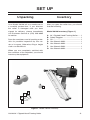
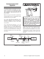
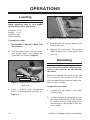
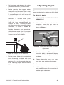
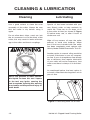
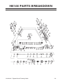
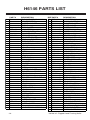
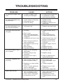
34° CLIPPED HEAD
FRAMING NAILER
MODEL H6146
INSTRUCTION MANUAL
COPYRIGHT © FEBRUARY, 2005 BY GRIZZLY INDUSTRIAL, INC.
WARNING: NO PORTION OF THIS MANUAL MAY BE REPRODUCED IN ANY SHAPE
OR FORM WITHOUT THE WRITTEN APPROVAL OF GRIZZLY INDUSTRIAL, INC.
#BL6906 PRINTED IN CHINA
SAFETY
For Your Own Safety Read Instruction Manual
Before Operating This Equipment
The purpose of safety symbols is to attract your attention to possible hazardous conditions. This manual uses a series of symbols and signal words which
are intended to convey the level of importance of the safety messages. The
progression of symbols is described below. Remember that safety messages by
themselves do not eliminate danger and are not a substitute for proper accident
prevention measures.
Indicates an imminently hazardous situation which, if
not avoided, WILL result in death or serious injury.
Indicates a potentially hazardous situation which, if
not avoided, COULD result in death or serious injury.
Indicates a potentially hazardous situation which, if
not avoided, MAY result in minor or moderate injury.
It may also be used to alert against unsafe practices.
NOTICE
This symbol is used to alert the user to useful information about proper operation of the equipment.
Safety Instructions for Machinery
1.
READ THROUGH THE ENTIRE
MANUAL BEFORE STARTING
MACHINERY. Machinery presents
serious injury hazards to untrained
users.
2.
MAKE SURE ALL GUARDS ARE
IN THEIR CORRECT PLACE AND
WORK CORRECTLY BEFORE
USING MACHINERY. NEVER
OPERATE MACHINE WITHOUT
GUARDS.
3.
ALWAYS USE ANSI APPROVED
SAFETY
GLASSES
WHEN
OPERATING MACHINERY.
4.
WEAR PROPER APPAREL. DO
NOT wear loose clothing, gloves,
neckties, rings, or jewelry which may
get caught in moving parts. Wear
protective hair covering to contain
long hair and wear non-slip footwear.
5.
NEVER OPERATE MACHINERY
WHEN TIRED, OR UNDER THE
INFLUENCE OF DRUGS OR
ALCOHOL. Be mentally alert at all
times when running machinery.
6.
ONLY ALLOW TRAINED AND
PROPERLY SUPERVISED PERSONNEL TO OPERATE MACHINERY. Make sure operation instructions are safe and clearly understood.
7.
KEEP CHILDREN AND VISITORS
AWAY. Keep all children and visitors a safe distance from the work
area.
8.
9.
13.
ALWAYS DISCONNECT FROM
POWER SOURCE BEFORE
SERVICING MACHINERY. Make
sure switch is in OFF position
before reconnecting.
14.
MAKE WORKSHOP CHILD
PROOF. Use padlocks, master
switches, and remove start switch
keys.
MAINTAIN MACHINERY WITH
CARE. Keep blades sharp and
clean for best and safest performance. Follow instructions for
lubricating and changing accessories.
15.
NEVER LEAVE WHEN MACHINE
IS RUNNING. Turn power OFF
and allow all moving parts to come
to a complete stop before leaving
machine unattended.
REMOVE ADJUSTING KEYS
AND WRENCHES. Make a habit
of checking for keys and adjusting wrenches before turning ON
machinery.
16.
CHECK FOR DAMAGED PARTS
BEFORE USING MACHINERY.
Check for binding and alignment of parts, broken parts, part
mounting, loose bolts, and any
other conditions that may affect
machine operation. Repair or
replace damaged parts.
17.
USE
RECOMMENDED
ACCESSORIES. Refer to the
instruction manual for recommended accessories. The use of
improper accessories may cause
risk of injury.
18.
DO NOT FORCE MACHINERY.
Work at the speed for which
the machine or accessory was
designed.
10.
DO NOT USE IN DANGEROUS
ENVIRONMENTS. DO NOT use
machinery in damp, wet locations,
or where any flammable or noxious
fumes may exist.
11.
KEEP WORK AREA CLEAN AND
WELL LIT. Clutter and dark shadows may cause accidents.
12. USE A GROUNDED EXTENSION
CORD
RATED FOR THE
MACHINE
AMPERAGE.
Undersized cords overheat and
reduce voltage. Replace extension
cords if they become damaged. DO
NOT use extension cords for 220V
machinery.
H6146 34° Clipped Head Framing Nailer
-1-
Additional Safety Instructions for Nailers
1.
HAND INJURIES: Do not place your
hands near the nail point of entry. A
nail can deflect and tear through the
surface of the workpiece, puncturing
your hand or fingers.
2.
COMBUSTIBLE GASES: Never
connect the nailer to pressurized
oxygen or other combustible gases
as a power source. Only use filtered, lubricated, and regulated
compressed air.
3.
4.
-2-
SAFE HANDLING: Never point the
nailer at others! Do not keep the
trigger pulled when loading fasteners, carrying, or holding tool. Carry
the nailer only by the handle, never
by any other part. Do not carry the
nailer by the air hose. Disconnect
the nailer from the air hose when
going up and down ladders.
CLEANING: Never use gasoline or
other flammable liquids to clean the
nailer; vapors in the nailer will ignite
by a spark and cause it to explode.
5.
HOSE USAGE: Make sure your
air hose is designed for the tool
in use, is in good condition, and
is long enough to reach your work
without stretching. However, an
overly long air hose in the work
area may be a tripping hazard.
6.
OPERATING QUESTIONS: If you
are not sure about the intended
operation, stop using the nailer.
Seek formal training or research
books or magazines that specialize in pneumatic tools.
7.
MAINTENANCE: Always disconnect air from the nailer when servicing or installing nails. During
maintenance, a nailer connected
to air may fire accidentally, causing serious personal injury.
8.
COMPRESSED AIR RATING: Do
not connect the nailer to compressed air that exceeds 120 PSI.
9.
CHECK VALVE: Do not use a
check valve or any other fitting that
allows air to remain in the tool.
H6146 34° Clipped Head Framing Nailer
Never point this nailer at yourself or
another person! Always pay attention
to the direction this nailer is pointed.
Use this tool with respect and caution
to lessen the possibility of operator or
bystander injury. Ignoring this warning
may result in serious personal injury.
Operating this nailer can propel
objects into the air, causing immediate eye damage. To protect yourself, always wear American National
Standards Institute (ANSI) approved
safety glasses or goggles when operating this equipment. In addition, this
nailer discharges at 85-90 decibels.
To protect your hearing, always wear
ANSI approved ear protection when
operating this nailer.
H6146 34° Clipped Head Framing Nailer
No list of safety guidelines can be
complete. Every shop environment
is different. Always consider safety
first, as it applies to your individual
working conditions. Use this and
other tools with caution and respect.
Failure to do so could result in serious personal injury, damage to
equipment or poor work results.
-3-
INTRODUCTION
Foreword
Contact Info
We are proud to offer the Grizzly Model
H6146 34º Clipped Head Framing Nailer.
This model is part of a growing Grizzly
family of fine pneumatic tools. When used
according to the guidelines set forth in this
manual, you can expect years of troublefree, enjoyable operation and proof of
Grizzly’s commitment to customer satisfaction.
If you have any comments regarding this
manual, please write to us at the following
address:
The Model H6146 is designed to toenail into corners. This nailer is ideal for
framing, pallet and crate assembly, and
deck, roof, fencing and sidewall sheathing
construction. The Model H6146 features
a 360° exhaust port, comfort grip rubber
handle, and economical air consumption
with low noise.
The specifications, details, and photographs in this manual represent the Model
H6146 as supplied when the manual was
prepared. However, owing to Grizzly’s policy of continuous improvement, changes
may be made at any time with no obligation on the part of Grizzly.
Grizzly Industrial, Inc.
C/O Technical Documentation
P.O. Box 2069
Bellingham, WA 98227-2069
Most importantly, we stand behind our
tools. If you have any service questions or
parts requests, please call or write us at
the location listed below.
Grizzly Industrial, Inc.
1203 Lycoming Mall Circle
Muncy, PA 17756
Phone: (570) 546-9663
Fax: (800) 438-5901
E-Mail: [email protected]
Web Site: http://www.grizzly.com
Machine Data
Nail Size ................ 7⁄64"-1⁄8" Shank Diameter
Nail Strip Angle ...................................... 34º
Nail Length .......... 2"-3½"(Clipped Headed)
Magazine Capacity ...................... 100 Nails
Air Inlet ...........................................¼" NPT
Weight .............................................81⁄3 lbs.
Operating Pressure .................. 70-120 PSI
-4-
Read the manual before operation.
Become familiar with this nailer, its
safety instructions, and its operation
before beginning any work. Serious
personal injury may result if safety or
operational information is not understood or followed.
H6146 34° Clipped Head Framing Nailer
SET UP
Unpacking
Inventory
Your Model H6146 left our warehouse in
a carefully packed box. If you discover
the nailer is damaged after you have
signed for delivery, please immediately
call Customer Service at (570) 546-9663
for advice.
After you open the nailer box, you should
find the following.
Save the containers and all packing materials for possible inspection by the carrier or its agent. Otherwise, filing a freight
claim can be difficult.
Model H6146 Inventory (Figure 1)
A.
B.
C.
D.
E.
F.
G.
34° Clippled Head Framing Nailer ..... 1
Safety Goggles ................................. 1
Oil ....................................................... 1
Hex Wrench 3MM .............................. 1
Hex Wrench 4MM .............................. 1
Hex Wrench 5MM .............................. 1
Hex Wrench 6MM .............................. 1
When you are completely satisfied with
the condition of the shipment, you should
inventory the equipment.
A
B
C
F
G
E
D
Figure 1. Model H6146 inventory.
H6146 34° Clipped Head Framing Nailer
-5-
Compressed Air
System
The Model H6146 is designed to be operated at 70-120 PSI using clean, dry, regulated, compressed air. DO NOT exceed
the maximum operating pressure for
your model.
Before using your new nailer, regulate the
air pressure on your air compressor to the
minimum PSI for your model.
An in-line filter/lubricator/regulator unit,
depicted in Figure 2, can be installed and
should be located as close to the nailer
as possible.
This filter/lubricator/regulator unit will
protect your tool from damaging water
build-up, allow you to adjust and maintain
constant air pressure to your tool, and
save you the inconvenience of having to
manually lubricate your tool every time
you use it.
Quick
Connector
Exceeding the maximum permissible
operating pressure may cause the
nailer to explode, blowing metal fragments in all directions. To protect
yourself from serious personal injury,
DO NOT allow your air compressor to
exceed the recommended pressure
when connected to this nailer!
Check the current Grizzly catalog for availability of this unit. If you plan on installing a filter/lubricator/regulator unit in your
compressed air system, always follow the
connection instructions that come with
the unit.
Quick
Connector Oiler
Filter
Air
Compressor
Nailer
Quick
Coupler
Air Hose
Quick Regulator
Coupler
Figure 2. Filter/Lubricator/Regulator Unit.
-6-
H6146 34° Clipped Head Framing Nailer
Safety Yoke
A safety yoke mechanism (bump fire) on
the nose of the nailer acts as a secondary safety device. When the trigger is
pressed, the nailer will not fire until the
safety yoke mechanism is depressed.
Before you use your nailer for the first
time, check the safety yoke mechanism to
ensure proper function. To do this:
1. DISCONNECT NAILER FROM THE
AIR SUPPLY!
2. Make sure the magazine is empty and
contains no nails.
3. Make sure the trigger and the safety
yoke mechanism move up and down
without sticking.
4. Connect the nailer to the air supply.
5. Without pressing the trigger, depress
the safety yoke mechanism against a
scrap piece of wood that is clean and
free of any knots, nails, or other foreign
objects.
— If the nailer does not fire, then the
safety yoke mechanism is working
correctly.
— If the nailer does fire when you
do this, immediately disconnect the
nailer from the air supply and call
Grizzly Technical Support at (570)
546-9663 for help.
— If the nailer fires when the trigger
is pulled, without the safety yoke
mechanism being depressed, then
the nailer is not working properly.
— If either of these two conditions
develop after you have used your
nailer for a period of time, check the
lubrication of these mechanisms.
The safety yoke is a mechanical
device that can fail. Never rely on the
safety yoke mechanism as an excuse
to point the nailer at yourself or any
bystanders. Serious injury may occur.
H6146 34° Clipped Head Framing Nailer
-7-
OPERATIONS
Loading
When replacing nails in your Model
H6146, follow these guidelines:
Diameter: 7⁄64"-1⁄8"
Length: 2"-31⁄2"
Capacity: 100
Strip Angle: 34°
Figure 4. Loading nails into magazine.
To load your nailer:
1. DISCONNECT NAILER FROM THE
AIR SUPPLY!
2. Grip the nailer firmly, pull the magazine pusher back, and engage the
catch lever as shown in Figure 3.
4. Slide the nails all the way down to the
nose of the nailer.
5. Release the catch lever. The pusher
slides forward until it rests against the
nail stick.
Operating
If you have not read the safety instructions in this manual, do not operate
the nailer.
Pusher
Catch Lever
Figure 3. Sliding pusher toward the
catch lever.
3. Insert a strip of nails, pointed-end
down, into the magazine as shown in
Figure 4.
Before you operate your nailer, place five
to six drops of the included oil into the
quick connect fitting where the nailer connects to the air supply.
To operate your nailer:
1. Connect the air supply to the quick
connect fitting.
2. To test for proper nail penetration, hold
the nailer perpendicular to the surface
of a piece of clean scrap wood that is
thick enough for the length of nails you
have loaded.
-8-
H6146 34° Clipped Head Framing Nailer
3. Pull the trigger and depress the safety
yoke mechanism on your workpiece.
4. Before pressing the trigger, make
sure your free hand and other body
parts are positioned out of the way
of a potential path of a nail in case of
deflection.
Deflection is caused when grain
irregularities, knots or foreign objects
inside the wood cause the nail to
change its path, resulting in the
nail puncturing the surface of the
workpiece, as shown in Figure 5.
Besides damaging your workpiece,
deflection can cause injury if your free
hand is securing the workpiece in the
location that the nail deflects.
Adjusting Depth
The nose of the gun houses a depth adjustment mechanism for setting the nail depth.
To adjust the depth:
1. DISCONNECT NAILER FROM THE
AIR SUPPLY!
2. If the nail is driven too far into the
workpiece, loosen the cap screw on
the safety nose with a 4mm wrench, as
shown in Figure 6.
Safety Nose
Safety Yoke
Cap Screw
Figure 6. Loosening cap screw for depth
adjustment.
Figure 5. Example of nail deflection.
5. Pull the trigger. If the nail drove into the
wood far enough, continue with your
intended operations. If the nail either
went too far or not far enough, then go
to the Adjusting Depth section on this
page.
3. Slide the safety nose (Figure 6) toward
the nailer body to drive nails deeper,
and away from the body to drive nails
less deep.
4. Tighten the safety nose cap screw
each time after making adjustments.
5. Connect to the air.
6. Pull the trigger and depress the safety
yoke mechanism on your workpiece to
test the depth adjustment.
H6146 34° Clipped Head Framing Nailer
-9-
Single/Bump Fire
Mode
Clearing Jammed
Nails
The nailer is designed to fire one nail at a
time, or one after another, using the safety
yoke mechanism.
A jammed nail must be cleared before
using the nailer again. The two places
where a nail can get jammed are the magazine and the discharge area.
To operate your nailer in single fire
mode:
To clear a jammed nail from the magazine:
1. Depress the safety yoke mechanism
against the workpiece.
1.
DISCONNECT NAILER FROM THE
AIR SUPPLY!
2. Pull the trigger, then remove your finger
from the trigger after the nail is driven.
2.
Pull back and lock the magazine pusher.
To operate your nailer in bump fire
mode:
3.
Remove the nail stick.
1. Pull the trigger.
4.
Locate and remove the jammed nail
with needle nose pliers. Release the
catch lever and let the pusher slide to
front of the magazine.
2. Press the safety yoke mechanism
against your workpiece and raise it
after the nail is driven.
3. Hold the trigger and repeat Step 2 to
drive more nails.
-10-
To clear a jammed nail from the discharge area:
1.
DISCONNECT NAILER FROM THE
AIR SUPPLY!
2.
Pull back and lock the magazine pusher in place.
3.
Remove all nails from the magazine.
4.
Locate the nail in the nailer nose, dislodge the nail with a tool that will fit in
the slot on the underside of the nose.
5.
Throw the damaged nail away and
insert a new nail stick that only contains clean, undamaged nails. DO
NOT use dirty or damaged nails!
6.
Release the catch lever and let the
pusher slide to the front of the magazine.
H6146 34° Clipped Head Framing Nailer
Replacing Pistons/ORings
5. The top of the piston should now be
visible inside the cylinder, which is
housed in the head of the nailer.
6. Open the magazine.
If you use your nailer day in and day
out, repair pistons are cheap insurance
against wasted down time and lost profits,
in the event that a piston or piston shaft
becomes worn out.
7. Watch the discharge area and push
the top of the piston with your finger.
You will see the piston shaft slide
down the discharge area.
8. With a long flathead screwdriver or
similarly shaped tool, push the piston
shaft back inside the nailer until you
can grip the piston head and remove
it from the cylinder. (Be careful not to
scratch the discharge area when pushing the piston shaft with the screwdriver.)
9. Place a new O-ring on the new piston
and apply a thin film of the nailer lubricating oil on the O-ring.
Always disconnect air from nailer
whenever servicing! During maintenance, a nailer connected to air may
fire accidentally, causing serious
personal injury!
To replace a piston:
1. DISCONNECT NAILER FROM THE
AIR SUPPLY!
2. Remove all nails from the magazine
cartridge.
3. Remove the four cap screws on the
top of the nailer, near the exhaust
port.
4. Remove the top cap.
H6146 34° Clipped Head Framing Nailer
10. Insert the new piston in the cylinder.
Make sure that the grooves on the
piston shaft line up with those on the
guide at the bottom of the cylinder.
The new piston should easily slide
into the cylinder. DO NOT force the
piston into the cylinder! If the piston
is not easily inserted, double-check the
alignment of the piston shaft with the
grooves on the guide.
11. After the piston is inserted correctly,
close the magazine. Replace the top
cap assembly and tighten the 4 cap
screws.
12. For more assistance, or to install a
complete O-ring set, refer to the appropriate breakdown diagram in the back
of this manual.
-11-
CLEANING & LUBRICATION
Cleaning
Lubricating
Use a good solvent to clean the nose
assembly of the nailer. Always be sure
that the nailer is dry before using it
again.
Special oil has been included with your
new Grizzly nailer to help maintain its
useful life. Place two to six drops of oil
in the nailer air inlet (as shown in Figure
7) before every use, or after 2 hours of
continuous use.
Do not allow dust, chips, sand, etc. into
the air connectors or into the body of the
nailer; this may result in leaks and damage to the nailer and the air couplings.
Wipe off any excess oil near the nailer
exhaust to avoid dust build-up. When
the oil that was included with the nailer
has been completely used, replace with
Grizzly Model G2820 Pneumatic Tool Oil.
Another option to manual oiling would be
to install a lubricator in your air compressor line. If your air compressor line already
has a lubricator, then regular lubrication
of your nailer will not be necessary. Just
make sure there is always oil in the lubricator.
As mentioned before, the best option is
to install a filter/lubricator/regulator unit in
your air line.
Never use gasoline or other flammable liquids to clean this tool. Vapors
in the tool may ignite, causing the
tool to explode. Ignoring this warning
may lead to serious personal injury or
even death!
Figure 7. Lubricating nailer via air inlet.
-12-
H6146 34° Clipped Head Framing Nailer
�
�
H6146 34° Clipped Head Framing Nailer
��
��
��
��
��
��
�
�
�
�
��
��
��
��
��
��
��
��
�
�
��
�
��
��
��
��
��
��
��
��
��
��
��
��
��
��
��
��
��
��
��
��
��
��
��
��
��
��
��
��
��
��
��
��
��
��
��
��
��
��
��
��
�� ��
��
��
��
��
�� ��
����
��
�� ��
��
��
��
�� ��
��
��
��
��
��
��
��
�� ��
��
��
��
��
��
��
H6146 PARTS BREAKDOWN
-13-
H6146 PARTS LIST
1
2
3
4
5
6
7
8
9
10
11
12
13
14
15
16
17
18
19
20
21
22
23
24
25
26
27
28
29
30
31
32
33
34
35
36
37
38
39
40
42
43
44
45
46
PART #
PH6146001
PH6146002
PH6146003
PH6146004
PH6146005
PSB06M
PLW03M
PH6146008
PSS07M
PH6146010
PH6146011
PH6146012
PH6146013
PH6146014
PH6146015
PH6146016
PH6146017
PH6146018
PH6146019
PH6146020
PH6146021
PH6146022
PH6146023
PH6146024
PH6146025
PH6146026
PH6146027
PH6146028
PH6146029
PH6146030
PH6146031
PH6146032
PH6146033
PH6146034
PH6146035
PH6146036
PH6146037
PH6146038
PH6146039
PH6146040
PH6146042
PRP02M
PH6146044
PH6146045
PH6146046
-14-
DESCRIPTION
SPCL CAP SCR M8-1.25 X 30
AIR DEFLECTOR
RUBBER WASHER
SPRING
SPRING WIRE
CAP SCREW M6-1 X 25
LOCK WASHER 6MM
CYLINDER CORE
SET SCREW M5-.8 X 5
CYLINDER COVER
HEAD VALVE PISTON
SPRING SEAT
COMPRESSION SPRING
O-RING 56.7 X 3
COLLAR
O-RING 42.3 X 5
PISTON
O-RING 57.5 X 3
O-RING 88 X 3
FIXED RING
SEALING RING
CYLINDER
BUMPER
GASKET
BODY
RUBBER WASHER
TRIGGER VALVE SEAT
O-RING 15 X 2.65
O-RING 17 X 1.5
TRIGGER VALVE GUIDE
O-RING 6.2 X 1.8
O-RING 6.4 X 2
O-RING 9 X 1.8
SWITCH SPRING
SWITCH PIPE
O-RING 2.5 X 1.5
O-RING 20.3 X 2.3
SWITCH SEAT
TRIGGER PIN
TRIGGER
SAFETY SPACER
ROLL PIN 3 X 16
SAFETY GUIDE
PIN 3 X 25
COMPRESSION SPRING
REFPART #
47 PSB03M
48 PW02M
49 PH6146049
50 PH6146050
51 PH6146051
52 PH6146052
53 PH6146053
54 PH6146054
55 PH6146055
56 PLW04M
57 PSB13M
58 PS14M
59 PH6146059
60 PW03M
61 PLN03M
62 PH6146062
63 PSB18M
64 PLN01M
65 PSB46M
66 PH6146066
67 PH6146067
68 PH6146068
69 PRP23M
70 PH6146070
71 PH6146071
72 PH6146072
73 PSB93M
74 PN07M
75 PH6146075
76 PH6146076
77 PH6146077
78 PH6146078
79 PH6146079
80 PH6146080
81 PSB38M
82 PW02M
83 PH6146083
84 PLN02M
85 PH6146085
86 PH6146086
87 PH6146087
88 PLW01M
89 PSB15M
90 PH6146090
91 PH6146091
92 PW02M
DESCRIPTION
CAP SCREW M5-.8 X 8
FLAT WASHER 5MM
ADJUSTING NUT
SAFETY YOKE
SAFETY NOSE
COPPER COLLAR
SAFETY NOSE CASE
O-RING 61.5 X 1.8
DRIVER GUIDE
LOCK WASHER 8MM
CAP SCREW M8-1.25 X 30
PHLP HD SCR M6-1 X 12
MAGAZINE
FLAT WASHER 6MM
LOCK NUT M6-1
DRIVE NAIL BAR
CAP SCREW M4-.7 X 8
LOCK NUT M4-.7
CAP SCREW M4-.7 X 40
SAFETY PIPE
SAFETY PIPE CASE
PIN CASE
ROLL PIN 4 X 44
PUSHER
PIN 3 X 20
PIN 5 X 20
CAP SCREW M3-.5 X 14
HEX NUT M3-.5
PIN 4 X 30
TORSION SPRING
SPRING CORE
PIN 5 X 12
RELEASE LATCH
TORSION SPRING
CAP SCREW M5-.8 X 25
FLAT WASHER 5MM
FIXED SEAT
LOCK NUT M5-.8
RUBBER HANDLE CASE
GASKET
END CAP
LOCK WASHER 5MM
CAP SCREW M5-.8 X 20
1/4" NPT MALE CONNECT
AIR PLUG COVER
FLAT WASHER 5MM
H6146 34° Clipped Head Framing Nailer
TROUBLESHOOTING
PROBLEM
CAUSE
ACTION
Air leaking at trigger valve
area.
1. O-rings in trigger valve
housing are damaged.
1. O-rings must be replaced
& operation of safety
yoke must be checked.
Air leaking between housing and hose.
1. Loose screws in housing.
2. Damaged O-ring.
3. Loose air fitting.
1. Tighten screws.
2. Replace O-ring.
3. Tighten air fitting & use
teflon tape.
Air leaking between housing and cap assembly.
1. Damaged seal.
1. Replace damaged seals.
Tool skips nails while discharging.
1. Air leaks.
1. Tighten screws and fittings.
2. Clean nose.
3. Clean magazine and
inspect/repair damage.
2. Dirt in nose.
3. Dirt or damage prevents
nails from moving freely in
magazine.
4. Inadequate air flow to tool.
5. Worn O-ring on piston or
lack of lubrication.
6. Damaged O-rings on trigger valve.
7. Worn bumper.
8. Cap seal leaking.
Tool runs slowly or has a
loss of power.
Fasteners frequently jam
the nailer.
1. Nailer is not sufficiently
lubricated.
2. Broken spring in cap
assembly.
3. Exhaust port in cap is
blocked.
1. Lubricate nailer.
1. Nails are the wrong size.
2. Nails are bent or dirty.
1. Use correct nails.
2. Use undamaged, clean
nails.
3. Tighten magazine.
3. Magazine or nose screws
are loose.
4. Driver or driver guide are
worn or damaged.
5. Nails are wrong angle.
Nailer does not fire.
4. Check fitting, hose, compressor & air pressure.
5. Replace piston O-ring.
Lubricate.
6. Replace trigger valve Orings.
7. Replace bumper.
8. Replace cap seal.
1. Nail is jammed in magazine or discharge area.
2. Piston shaft is damaged.
3. Air pressure too low.
H6146 34° Clipped Head Framing Nailer
2. Replace spring.
3. Clean or replace damaged internal parts.
4. Replace worn or damaged parts.
5. Use correct angle nails.
1. Clear nailer magazine or
discharge area.
2. Replace piston shaft.
3. Check/increase air pressure.
-15-
WARRANTY AND RETURNS
Grizzly Industrial, Inc. warrants every product it sells for a period of 1 year to the original
purchaser from the date of purchase. This warranty does not apply to defects due directly
or indirectly to misuse, abuse, negligence, accidents, repairs or alterations or lack of
maintenance. This is Grizzly’s sole written warranty and any and all warranties that may
be implied by law, including any merchantability or fitness, for any particular purpose, are
hereby limited to the duration of this written warranty. We do not warrant or represent that
the merchandise complies with the provisions of any law or acts unless the manufacturer so
warrants. In no event shall Grizzly’s liability under this warranty exceed the purchase price
paid for the product and any legal actions brought against Grizzly shall be tried in the State
of Washington, County of Whatcom.
We shall in no event be liable for death, injuries to persons or property or for incidental,
contingent, special, or consequential damages arising from the use of our products.
To take advantage of this warranty, contact us by mail or phone and give us all the details.
We will then issue you a “Return Authorization Number,” which must be clearly posted on
the outside as well as the inside of the carton. We will not accept any item back without this
number. Proof of purchase must accompany the merchandise.
The manufacturers reserve the right to change specifications at any time because they
constantly strive to achieve better quality equipment. We make every effort to ensure that
our products meet high quality and durability standards and we hope you never need to
use this warranty.
Please feel free to write or call us if you have any questions about the machine or the
manual.
Grizzly Industrial, Inc.
1203 Lycoming Mall Circle
Muncy, PA 17756
Phone: (570) 546-9663
Fax: (800) 438-5901
E-Mail:
[email protected]
Web Site: http://www.grizzly.com
Thank you again for your business and continued support. We hope to serve you again
soon!
WARRANTY CARD
Name _________________________________________________________________________
Street ________________________________________________________________________
City____________________State________Zip_________
Phone Number____________E-Mail___________________FAX ____________
Model # H6146 34° Clipped Head Framing Nailer Serial#______________Order #__________
The following information is given on a voluntary basis. It will be used for marketing purposes to help
us develop better products and services. Of course, all information is strictly confidential.
1. How did you learn about us?
___Advertisement
___Friend
___Catalog
___Card Deck
___World Wide Web
___Other__________________________
2. What is your annual household income?
___$20,000-$29,999 ___$60,000-$69,999
___$30,000-$39,999 ___$70,000-$79,999
___$40,000-$49,999 ___$80,000-$89,999
___$50,000-$59,999 ___$90,000 +
3. What is your age group?
___20-29
___50-59
___30-39
___60-69
___40-49
___70 +
4. How long have you been a woodworker?
___0 - 2 Years
___8 - 20 Years
___2 - 8 Years
___20+ Years
5. How would you rank your woodworking skills?
___Simple
___Advanced
___Intermediate
___Master Craftsman
6. What stationary woodworking tools do you own?
Check all that apply.
___Air Compressor
___Panel Saw
___Band Saw
___Planer
___Drill Press
___Power Feeder
___Drum Sander
___Radial Arm Saw
___Dust Collector
___Shaper
___Spindle Sander
___Jointer
___Table Saw
___Lathe
___Mortiser
___Wide Belt Sander
___Horiz.Boring Machine
___Vacuum Veneer Press
___Other______________________________
7. How many of your woodworking machines are
Grizzly? _______________________________
8. Which benchtop tools do you own? Check all
that apply.
___1"x42" Belt Sander ___6" - 8" Grinder
___5" - 8" Drill Press ___Mini Lathe
___8" Table Saw
___8" - 10" Bandsaw
___Scroll Saw
___Disc/Belt Sander
___Spindle/Belt Sander ___Mini Jointer
___10"-12"Thickness Planer
Other____________________________________
9. How many of the machines checked above are
Grizzly? __________________________________
10. Which portable/hand held power tools do you own?
Check all that apply.
___Belt Sander
___Orbital Sander
___Biscuit Joiner
___Palm Sander
___Circular Saw
___Portable Planer
___Detail Sander
___Saber Saw
___Drill/Driver
___Reciprocating Saw
___Miter Saw
___Router
Other_________________________________
11. What machines/supplies would you like Grizzly
Industrial to carry?
________________________________________
________________________________________
________________________________________
________________________________________
12. What new accessories would you like Grizzly
Industrial to carry?
________________________________________
________________________________________
________________________________________
________________________________________
13. What other companies do you purchase your tools
and supplies from?
________________________________________
________________________________________
________________________________________
________________________________________
14. Do you think your purchase represents good
value?
___Yes
___No
15. Would you recommend Grizzly to a friend?
___Yes
___No
16. Would you allow us to use your name as a reference for Grizzly customers in your area? Note: We
never use names more than three times.
___Yes
___No
17.Comments:________________________________
_________________________________________
_________________________________________
_________________________________________
Send a Grizzly Catalog to a friend:
Name________________________________
Street________________________________
City______________State______Zip_______
FOLD ALONG DOTTED LINE
Place
Stamp
Here
GRIZZLY INDUSTRIAL, INC.
P.O. BOX 2069
BELLINGHAM, WA 98227-2069
TAPE ALONG EDGES--PLEASE DO NOT STAPLE