1
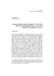
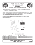
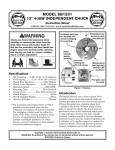
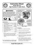
MODEL SB1044
CUTTING FLUID KIT
Instruction Sheet
PHONE: (360) 734-1540 • www.southbendlathe.com
BIOLOGICAL & POISON
HAZARD!
Use the correct personal
protection equipment
when handling cutting
fluid. Follow federal, state,
and fluid manufacturer
requirements for proper
disposal.
Introduction
This cutting fluid kit is for the Model SB1029
Surface Grinding Machine. The system is
designed to pump water-soluble cutting fluid to
minimize grinding wheel wear, load-up, glazing,
and heat. Using cutting fluid helps maximize
the quality of workpiece results, especially on
materials that should not be ground dry.
Specifications
•
•
•
•
•
•
•
•
•
•
Motor........................................................1⁄8 HP
Phase & Cycle.................. 3-Phase & 50/60 Hz
Voltage.............................................220V/440V
Current...................................... 0.3/0.15 Amps
Pump Type...................................................Jet
Pump Flow......................................... 8.2 GPM
Cutting Fluid Type.......... Water-Soluble Only
Maximum Tank Capacity....................... 9 Gal.
Net Weight.............................................. 73 lbs
Country of Origin................................. Taiwan
If you need help with your new model
SB1044 Cutting Fluid Kit, contact us at:
PHONE: (360) 734-1540
FAX: (360) 676-1075
EMAIL: [email protected]
Figure 1. Model SB1044.
Unpacking
This item was carefully packaged to prevent
damage during transport. If you discover any
damage, please immediately call Customer
Service at (360) 734-1540 for advice. You may
need to file a freight claim, so save the containers
and all packing materials for possible inspection
by the carrier or its agent.
Inventory
Item: Qty
• Tank Assembly w/Pump................................. 1
—Drain Hose 1 3⁄4" x 5'..................................... 1
—Hose Clamp 1 3⁄4" ......................................... 1
—Delivery Hose 1⁄2'' x 9'.................................. 1
—Hose Clamp 1 3⁄4''.......................................... 1
—Flex Conduit Power Cord 9'........................ 1
—Drain Adapter.............................................. 1
—Swivel Caster Wheels.................................. 4
• Splash Guard.................................................. 1
—Button Head Cap Screw M6-1 x 10............ 4
—Front & Rear Splash Panel................... 1 Ea
• Coolant Trough............................................... 1
Copyright © December, 2010 by South Bend Lathe Co.
WARNING: No portion of this manual may be reproduced without written approval.
#CR13482 Printed in Taiwan
Model SB1044
I NSTR UCTIONS
Mfg. Since 6/10
Installation
During the installation process of your cutting
fluid kit, you'll need the following items:
For Power Connection
•
A power source that meets the minimum
circuit requirements for this machine.
•
A qualified electrician to ensure a safe and
code-compliant connection to the power
source.
For Assembly
•
•
•
•
•
Phillips Screwdriver #2
Cotton Rags and Silicone Sealant
Hex Wrenches 3, 5mm
Safety Goggles
Wrench 27mm
Spash
Guard
Trough
Drain
Cover
Chip
Shield
Drain
Hose
To install the cutting fluid kit:
1. DISCONNECT THE SURFACE GRINDER
FROM POWER.
2. Fasten the four swivel caster wheels to the
tank, and make sure the drain plug is tight.
Tip: Place one or more strong magnets at the
bottom of the tank to collect fine metal
particles from the cutting fluid.
3. Route the pump power cord around the
backside of the surface grinder, or fasten it
up and away from the floor.
4. Connect the SB1044 power cord to the
surface grinder as outlined on the Model
SB1029 Pump Connection Wiring
Diagram on Page 7.
If the surface grinder uses a 440V power
supply, the pump motor must be rewired as
shown in the OPTIONAL 440V 3-PHASE
CONNECTION diagram on Page 7.
5. Remove the existing chip shield and drain
cover from the table, as shown in Figure 2.
Retain the fasteners to install the SB1044
splash guard and port.
Note: For shipping purposes, the front and rear
splash panels are fastened together with four
wing nuts on the rear splash guard wall.
-2-
Port
Tank
SB
10
Connect Delivery
Hose to Desired
Cutting Fluid Nozzle
29
Power
Cord
Figure 2. Cutting fluid system installation.
6. Apply silicone sealant to the mounting flange
of the port shown in Figure 2.
7. Using the fasteners from the machine in
Step 5, install the port, splash guard, and
the trough to the machine, as shown in
Figure 2.
8. Insert one end of the drain hose into the
tank, and fasten the other end to the trough
using the hose clamp.
9. Route the delivery hose out of the way and
fasten the delivery hose to your desired
cutting fluid nozzle with the hose clamp.
10. Fill the tank with premixed water soluble
cutting fluid.
Mfg. Since 6/10
I NSTR UCTIONS
Operation
Model SB1044
To use the cutting fluid system:
Only use high quality water-soluble cutting
fluid in this system. Never attempt to pump
straight cutting oils or kerosene. If you do, the
higher viscosity of the oil will overload the motor,
causing damage, or flammable liquids may
ignite.
Following the cutting fluid manufacturer’s
guidelines, check and maintain the specific
gravity of the cutting fluid to its required level.
Change the fluid when it becomes overly dirty,
rancid, or contaminated.
1. Make sure the cutting fluid is properly
serviced and the tank is filled.
2. Put on the necessary personal protection
equipment.
3. Position the cutting fluid nozzle for your
operation.
4. Use the control panel coolant switch to turn
the cutting fluid pump ON.
BIOLOGICAL & POISON
HAZARD!
Use the correct personal
protection equipment
when handling cutting
fluid. Follow federal, state,
and fluid manufacturer
requirements for proper
disposal.
Coolant Switch
Figure 3. SB1029 control panel.
Running the pump without adequate fluid in
the tank may permanently damage it. This
damage is not covered by warranty.
5. Adjust the flow of cutting fluid for the type of
flooding required.
Note: Promptly clean any splashed cutting fluid
from the floor to avoid a slipping hazard.
-3-
Model SB1044
I NSTR UCTIONS
Mfg. Since 6/10
Maintenance
When you replace the old cutting fluid, take the
time to thoroughly clean out both sides of the
tank. Make sure to dispose all old fluid according
to local regulations. Cutting fluid is considered
hazardous waste by the EPA. Follow all disposal
and storage guidelines when changing and
disposing of cutting fluid.
Tip: Maintaining the specific gravity of cutting
fluid with a hydrometer or refractometer can
greatly extend the life of cutting fluid and
reduce operating costs. Properly maintained
cutting fluid allows for better cutting and longer
grinding wheel life.
Items Needed:
Qty
New Pre-Mixed Cutting Fluid................. 9 Gallons
Safety Goggles........................................................ 1
Rubber Gloves................................................1-Pair
Wrench 28mm........................................................ 1
5-Gallon Bucket w/Lid........................................... 2
Hex Wrench 3mm.................................................. 1
Hot Soapy Water or Mineral Spirits..... As Needed
Waste Coolant Drain Hose.................... As Needed
Cotton Rags............................................ As Needed
Mineral Spirits....................................... As Needed
Magnets..................................................... Optional
To change the cutting fluid:
1. Remove the four button head screws and
washers from the tank cover.
2. Open the tank cover so the cutting fluid can
be seen.
3. Fasten the waste coolant drain hose to
the coolant nozzle. If the connection is
questionable, use a hose clamp to ensure it
does not leak.
4. Place the other end of the drain hose into one
of the 5-gallon buckets. Clip or wire the hose
in place so it won’t come out of the bucket
when the pump is turned ON.
5. Open the flow lever on your cutting-fluid
nozzle all the way open, and turn the cutting
fluid pump ON. Do not leave the area as
you will need transfer the hose to the other
bucket to prevent over-filling and spills.
-4-
Leaving the pump running with an empty
cutting fluid tank can damage a pump. Shut
the pump OFF immediately when the fluid
slows or stops coming from the drain hose.
6. When the fluid stops flowing, immediately
turn the pump OFF, and disconnect the
drain hose.
7. Disconnect the machine from power, lift the
pump and cover from the tank, and set it
aside for cleaning and inspection.
8. Remove the drain plug, and pour the
remaining cutting fluid from the tank into
the 5-gallon bucket.
9. Seal the buckets with their lids.
10. Mark or tag the buckets as hazardous waste
(according laws and regulations).
11. Using a solution of soapy hot water and rags,
clean and dry the tank, the pump, and the
cover. If the tank residue is oily, clean with
mineral spirits instead of soapy water.
Tip: Place one or more strong magnets at the
bottom of the tank to collect fine metal
particles from the cutting fluid.
12. Reinstall the drain plug.
13. Mix the new cutting fluid with water in
the required ratio until the fluid reaches
the specific gravity indicated by the fluid
manufacturer.
14. Pour the cutting fluid into the tank. To
prevent the pump from running dry, never
use less than four gallons of cutting fluid.
15. Point the cutting fluid nozzle into the coolant
trough and open the valve.
16. Turn the machine and pump ON to verify
that fluid cycles properly, then turn it OFF.
I NSTR UCTIONS
Mfg. Since 6/10
Model SB1044
Troubleshooting
Symptom
Little or no cutting
fluid is being
pumped. Pump and
motor may also
vibrate or be noisy.
Possible Cause
Possible Solution
1. No power; voltage is incorrect.
1. Switch power supply ON/verify machine and pump
voltages match.
2. Blown fuse/tripped circuit breaker
at main panel.
2. Correct the cause of overload, then reset/replace
fuse or breaker.
3. Coolant level is too low, and pump
cavitation is occurring.
3. Fill coolant tank with a minimum of four gallons of
cutting fluid.
4. Coolant is incorrect, or is too thick
and incorrectly mixed.
4. Use water-soluble cutting fluid, or add water to
lower fluid viscosity.
5. Pump is operating in reverse.
5. Pump power supply wires are connected out of
phase. Swap any two pump power supply power
leads.
6. Motor or cover is loose.
6. Tighten any loose fasteners.
7.
Debris is obstructing pump suction
or impeller is damaged.
7.
Remove pump, remove impeller cover, clean and
replace as required.
8. Plug or receptacle is corroded or
mis-wired.
8. Clean/retighten contacts; correct the wiring.
9. Break or short in wiring; or loose
connections.
9. Trace/replace broken or corroded wires; fix loose
connections.
10. Pump ON/OFF switch at fault.
10. Replace switch.
11. Motor connection wired incorrectly.
11. Wire motor correctly (refer to inside junction box
cover or manual).
12. Emergency stop button is at fault.
12. Reset or replace emergency stop switch assembly.
13. Thermal relay has tripped.
13. Improve pump motor cooling and airflow.
Disconnect machine from power, manually reset
thermal relay, and slightly turn-up trip setting.
14. Transformer is at fault.
14. Test/replace transformer.
15. Contactor not energized/has poor
contacts.
15. Test all legs for power, test field coil and replace if
at fault.
16. Motor at fault.
16. Test for shorted windings, bad bearings and repair
or replace.
-5-
I NSTR UCTIONS
Model SB1044
Mfg. Since 6/10
Electrical Safety Instructions
These pages are accurate at the time of printing. In the constant effort to improve, however, we may
make changes to the electrical systems of future machines. Study this section carefully. If you see
differences between your machine and what is shown in this section, call Technical Support at (360)
734-1540 for assistance BEFORE making any changes to the wiring on your machine.
1.
2.
3.
4.
Shock Hazard: It is extremely dangerous to
perform electrical or wiring tasks while the
machine is connected to the power source.
Touching electrified parts will result in
personal injury including but not limited to
severe burns, electrocution, or death. For
your own safety, disconnect machine from
the power source before servicing electrical
components or performing any wiring tasks!
5.
Circuit Requirements: Connecting the
6.
Capacitors/Inverters: Some capacitors and
power inverters store an electrical charge for
up to 10 minutes after being disconnected
from the power source. To reduce the risk of
being shocked, wait at least this long before
working on capacitors.
7.
Wire/Component Damage: Damaged wires
8.
Experiencing Difficulties: If you are
Wire Connections: All connections must be
tight to prevent wires from loosening during
machine operation. Double-check all wires
disconnected or connected during any wiring
task to ensure tight connections.
Modifications: Using aftermarket parts or
modifying the wiring beyond what is shown
in the diagram may lead to unpredictable
results, including serious injury or fire.
Motor Wiring: The motor wiring shown
in these diagrams is current at the time of
printing, but it may not match your machine.
Always use the wiring diagram inside the
motor junction box.
machine to an improperly sized circuit will
greatly increase the risk of fire. To minimize
this risk, only connect the machine to a
power circuit that meets the minimum
requirements given in this manual.
or components increase the risk of serious
personal injury, fire, or machine damage. If
you notice that any wires or components are
damaged while performing a wiring task,
replace those wires or components before
completing the task.
experiencing difficulties understanding the
information included in this section, contact
our Technical Support at (360) 734-1540.
WIRING DIAGRAM COLOR KEY
BLACK
BLUE
WHITE
BLUE
BROWN
NOTICE:
-6-
RED
PINK
WHITE
GREEN
LIGHT
BLUE
PURPLE
YELLOW
GREEN
GRAY
ORANGE
TURQUIOSE
YELLOW
The photos and diagrams included in this section are best viewed in color. You can
see them in color at www.southbendlathe.com.
I NSTR UCTIONS
Mfg. Since 6/10
Model SB1044
Model SB1029 Pump Connection Wiring Diagram
!
If the pump motor runs in a
counterclockwise direction as
viewed through the motor shaft
sight glass, disconnect machine
from power and swap wire
positions U1 and V1 on the
terminal bar shown below.
Fuses
4A
1
To Oil
Pump
0
4
To Control
Panel
OPTIONAL
440V 3-PHASE
CONNECTION
1
NO
98
2
3
To Oil
Pump
1
3
0
V
0
V
W
3
4
0
U
V
W
4
PREWIRED
L1 3
L2 5
L3
220V 3-PHASE
CONTACTOR
Allen Bradley
CONNECTION
C09400
To
Motor
To
Power Cord
2 T1
4
2
1
T2
U1
V1
V1
16
5
4
6 T3
7
8 T4
3
THERMAL
RELAY
6
95
W1
W1
Gn
U
2
OPTIONAL
AMP
440V 3-PHASE
5
4
U1 CONNECTION
6
0
R1
1
To
Motor
To
Power Cord
7
U
2
6
7
1
2
4
6
2 3 3
4
1
3
3
R1 T1
2
1
T
1
To Control
Panel
GND
R1
R
S
U1 V1 W1
R1
1
T
T1
1
S
R1
U
R
0
Fuses
4A
W1
V
T
W
U
S
V
0
V1
4
4
U1
3
3
V
2
2
U1 V1 W1 R
7
U
1
T1
R1
1
W
6
0
2 3 3
7
1
6
R1 T1
4
SB1029 Surface
Grinder
W
R1
O
2
NC
96
NO
98
8
35
4U
Gn
97
V
W
U1
NO
Ground
98
V1
W1
Ground
Ground
6
Gn
Ground
5
4
-7-
W
I NSTR UCTIONS
Model SB1044
Parts Diagram
26
17
Parts List
24
3
14
2 25
12
4
26
18
1
5
21
22
10 17
23
18
19
11 18
6
13
8
15
16
12
20
Mfg. Since 6/10
17 9
7
Please Note: We included this parts breakdown for
service purposes only. Not all parts may be available as
individual items.
REF
PART #
DESCRIPTION
1
2
3
4
5
6
7
8
9
10
11
12
13
14
15
16
17
18
19
20
21
22
23
24
25
26
PSB1044001
PSB1044002
PSB1044003
PSB1044004
PSB1044005
PSB1044006
PSB1044007
PSB1044008
PSB1044009
PBHS09M
PWN01M
PSBHS35M
PCAP26M
PCAP24M
PBHS03M
PW01M
PW02M
PW03M
PSB1044019
PSB1044020
PSB1044021
PSB1044022
PSB1044023
PSB1044024
PSB1044025
PSB1044026
CUTTING FLUID TANK
HINGED TANK COVER
MOTOR/PUMP 1/8HP 3-PH 220V/440V
FLUID DELVERY HOSE 1/2" X 9ft
ELBOW FITTING
SWIVEL CASTER
SPLASH GUARD
COOLANT TROUGH
DRAIN PORT
BUTTON HD CAP SCR M6-1 X 12
WING NUT M6-1
BUTTON HD CAP SCR M5-.8 X 10
CAP SCREW M6-1 X 12
CAP SCREW M5-.8 X 16
BUTTON HD CAP SCR M8-1.25 X 16
FLAT WASHER 8MM
FLAT WASHER 5MM
FLAT WASHER 6MM
REAR SPLASH PANEL
FRONT SPLASH PANEL
HOSE CLAMP 1-3/4"
DRAIN HOSE 1-3/4" X 5ft
PLUG
FLEX-CONDUIT POWER CORD 9ft
STRAIN RELIEF
HOSE CLAMP 3/4"
Warranty
This quality product is warranted by South Bend Lathe Company to the original buyer for one year
from the date of purchase. This warranty does not apply to consumable parts, or defects due to any
kind of misuse, abuse, negligence, accidents, repairs, alterations or lack of maintenance. We do not
reimburse for third party repairs. In no event shall we be liable for death, injuries to persons or
property, or for incidental, contingent, special or consequential damages arising from the use of our
products.
We do not warrant or represent that this machine complies with the provisions of any law, act, code,
regulation, or standard of any domestic or foreign government, industry, or authority. In no event
shall South Bend’s liability under this warranty exceed the original purchase price paid for this
machine. Any legal actions brought against South Bend Lathe Company shall be tried in the State of
Washington, County of Whatcom.
This is the sole written warranty for this machine. Any and all warranties that may be implied by
law, including any merchantability or fitness, for any purpose, are hereby limited to the duration of
this warranty. To take advantage of this warranty, contact us by mail or phone to give us the details
of the problem you are having.
Thank you for your business and continued support.
-8-