1
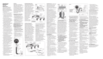
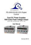
User Manual of
Precision AC- DC Power Supply: Dual Channel 0-30V ,
5A max or 0-60V single channel
AA Portable Power Corp (http://www.batteryspace.com)
Address: 860 S, 19th St, Unit A, Richmond, CA, 94804
Tel: 510-525-2328
Fax: 510-439-2808
Email: [email protected]
Prepared & Approved by Max (20/10/10)
1. INTRODUCTION
Adjustable DC power supply are designed to be used in applications such as powering
operational amplifier, push pull stages, logic circuit and definition systems where plus and
minus voltages are required to track with an insignificant error, and in any application
where three independent power supplies housed in a single package represent an operating
convenience.
The instruments consist of two identical, independently adjustable and one fixed 5V/3A
DC power supplies. A front panel switch selects one of three modes of operation:
independent, series and parallel. In the independent mode, the output voltage and current of
each supply are controlled separately, and each supply is isolated up to 300V from output to
chassis or output to output .In the tracking mode, both outputs are automatically connected
in series or parallel, and the controls of the left supply adjust the magnitudes of both the
positive and negative output voltages. Because the outputs are connected in a tracking
configuration, any internal disturbance in the master supply (such as drift or ripple) will
cause an equal percentage change in the outputs of both the supplies.
Each power supply is a completely transistorized, well-regulated, constant
voltage/constant current supply that will furnish full rated output voltage at the maximum
output current or can be continuously adjusted throughout the output range. The front
panel current controls can be used to establish the output current limit (overload or shout
circuit) when the supply is used as a constant voltage source (independent or tracking modes)
and the voltage controls can be used to establish the voltage limit (ceiling) when the supply is
used as a constant current source(independent mode only).The supply will automatically
cross over from constant voltage to constant current operation(current limited operation in
the tracking mode) and vice versa if the output current or voltage exceeds these preset
limits. Each supply had its own front panel meter that can measure output voltage and
current. One power supply may be used as a master supply controlling, one slave supplies
furnishing various voltages or current for a system. When operated with the front panel
mode switch in the tracking position, the instrument is automatically internally connected in
auto-tracking configuration.
Another feature of this instrument is its output ON/OFF key.
a. For model A/B, it is only the key to cut off or resume the output as other similar
instrument.
(3) Parallel Tracking Operation
In the parallel tracking mode of operation, both supplies are strapped together (in
parallel). This allows for a rating voltage supply with a double rating current capability.
Only the MASTER output terminals are used for parallel tracking operation. In the parallel
tracking mode, the SLAVE supply output voltage and current are tracking the MASTER
supply output voltage and current.
A. Set the power supplies to the TRACKING PARALLEL mode by engaging both
TRACKING switches.
B. Because both voltage and current of the SLAVE supply track the MASTER supply,
the maximum current and voltage are set using the MASTER controls. Using the MASTER
supply output jacks, follow the instructions for "Setting Current Limit" (4-2 Section).
Remember that the actual current output at the MATER supply output jack is double the
reading on the SLAVE indicator meter. Then push the output on/off key to enter voltage and
current setting.
C. Adjust the output voltage to the desired level using the MASTER VOLTAGE controls.
D. Turn off the power supply and the equipment to be powered during hook-up.
E. Connect the positive polarity of the device being powered to the red (+) terminal of the
MASTER power supply.
F. Connect the negative polarity of the device being powered to the black (-) terminal of
the MASTER power supply.
The configuration as shown in Fig.4-5.
+
_
M ASTER
LOAD
S LAVE
LOAD
+
POWER
SUPPLY
_
Fig .4-5 Paral lel Tracki ng Op eratio n.
+
_
MAST ER
LOAD
+
POWER
SUPPLY
_
SLAV E
Fig.4-3 Single Supply
If the chassis or common of the equipment being powered is separate from both positive and
negative polarity power inputs.
The output of the SLAVE (negative) supply is tracking the output of the MASTER
(positive) supply. The configuration is shown in
MAST ER
GND
LOAD
SLAVE
POWER
SUPPLY
Fig .4-4 Po s itiv e and Neg ati v e Sup pl y.
b. For model C/D, it is not only the key to cut off or resume the output, but also be endowed
with a new function which its Kindred has not. This function is that when the output has
been cut off, the both intending voltage and current can be preset, though in model A/B
condition, only the intending voltage can be adjusted. It means that CC preset is very easy as
CV preset.
Also in this way, an over current by any unknown load can be avoided. So the new
function of the key is a safety design.
Especially this feature is very important to the student use
2. SPECIFICATIONS
2-1 General
Power Source: AC 110V/220V ( ±10%) 50/60Hz
Operation Temperature & Humidity 0 C to 40 C, <80%
Storage Temperature & Humidity -10 C to 70 C, <70%
Accessories
Power cord ┈┈┈┈┈┈┈┈┈┈┈┈┈┈┈┈┈┈┈┈┈┈┈┈1
Operation Manual┈┈┈┈┈┈┈┈┈┈┈┈┈┈┈┈┈┈┈┈┈┈1
Rating
Model
Specifications
A
B
C
D
Output voltage
2H 0~30V
2H 0~30V
2H 0~30V
2H 0~30V
Output current
2H 0~3A
2H 0~5A
2H 0~3A
2H 0~5A
Output fixed
5V,3A
5V,3A
Output on/off
V/A initializes
X
5V,3A
X
√
5V,3A
√
Dimensions: 245(W)H140(H)H345(D)mm
Weight: Approx.8kg
2-2 Operation Mode
(1). Independent: Two independent outputs and 5V fixed output.
Output from 0 to rating volts and 0 to rating amperes.
(2). Series:
Output from 0 to ± rating volts at rating amperes each.
Output from 0 to double rating volts at rating amperes.
(3). Parallel:
Output from 0 to double rating amperes at rating volts.
2-3 Constant Voltage Operation
(1). Output current range
0~rating voltage continuously adjustable.
(2). Regulation
Line regulation≤0.01%+3mV.
Load regulation≤0.01%+3mV (rating current≤3A)
Load regulation≤0.02%+5mV (rating current>3A)
(3). Recovery time
≤100us (50% Load change, Minimum load 0.5A)
(4). Ripple & Noise
≤1mV rms, 5Hz~1MHz.
(5). Temperature coefficient
≤300PPM/ C
2-4 Constant Current Operation
(1). Output current range
0~rating current continuously adjustable.
(2). Regulation
Line regulation≤0.2%+3mA.
Load regulation≤0.2%+3mA.
(3). Ripple current
≤3mA rms.
2-5 Tracking Operation
(1). Parallel operation
Regulation
Line regulation≤0.01%+3mV.
Load regulation≤0.01%+3mV (rating current≤3A)
≤0.02%+5mV (rating current>3A)
(2). Series operation
Regulation
Line regulation≤0.01%+5mV.
Load regulation≤300mV
A. Positive and Negative supply (Fig.4-4).
(2)
Series Tracking Operation
When the series tracking mode of operation is selected, the positive (red) terminal of
the SLAVE supply output is internally connected to the negative (black) terminal of the
MASTER supply.
In the series tracking mode, the maximum output voltage of both MASTER and
SLAVE supplies can be simultaneously varied with one control. The maximum SLAVE
supply voltage is automatically set to the same value as the MASTER supply by using the
MASTER VOLTAGE controls.
A. Set the power supplies to the TRACKING SERIES mode by engaging the left
TRACKING switch and release the right
TRACKING switch. In this case, the output voltage (across the two supplies) is
actually double the displayed value.
For example, if the MASTER display is set for voltage metering and the SLAVE
display for current metering, the output voltage across the MASTER positive (red) terminal
and the SLAVE negative (black) terminal would be double the reading on the MASTER
LED Display (since both supplies are putting out the same voltage). The actual output
current would be the value read from the SLAVE LED Display (since the two supplies are
wired in series, current flowing through each supply must be equal).
B . Set the SLAVE CURRENT control the fully clockwise position. The maximum
current is set using the MASTER CURRENT control. Follow the instructions for "Setting
Current Limit" (INDEPENDENT USE OF "MASTER" OR "SLAVE" SUPPLY section of
this manual, using the MASTER CURRENT control.
NOTE:
Because the supplies are being used in series, either CURRENT control can be used
to set maximum current. If desired, the MASTER CURRENT control can be rotated fully
clockwise and the SLAVE CURRENT control can be used to adjust the maximum current
value. Because current through the two supplies must be equal when they are being used in
series, the lower
CURRENT control setting will set the maximum output current.
C. Adjust the output voltage the desired level using the MASTER VOLTAGE controls.
D. Turn off the power supply and the equipment to be powered during hook-up.
E. If "single supply" operation is desired, this allows the power supply to be used as
twice the voltage and rating current simply by using the negative (black) terminal of the
SLAVE supply and the positive (red) terminal of the MASTER supply, the configuration as
shown in Fig.4-3.
4-4 Operation Mode
(1) Independent Operation
The "MASTER" and "SLAVE" supplies each provide a 0 to rating volts output at
up to rating amps. This procedure covers the use of the MASTER and SLAVE supplies only
when they are used independently from one another. When used in the INDEPENDENT
operating mode, the operating controls of the two power supplies are completely
independent and either supply can be used individually or both can be used simultaneously.
A. Disengage both TRACKING mode switches (both switches out) so that the power
supply is in the INDEPENDENT operating mode.
B. Adjust "Voltage" control and "Current" control to the desired output voltage and
current.
C. Turn off the power supply and the equipment to be powered during hook-up.
D. Connect the positive polarity of the device being powered to the red (+) terminal of
the power supply.
E. Connect the negative polarity of the device being powered to the black (-) terminal
of the power supply.
F. Fig.4-2 illustrates the connection procedure.
+
_
M ASTER
LOAD
SLAVE
LOAD
+
POWER
SUPPLY
_
Fig .4-2 Indep endent Op eratio n.
Slave tracking error≤0.5%+10mV of the master
(No load, with load add Load regulation≤300mV).
B. Single supply (Fig.4-3)
2-6
Meter
A. Display: 3 Digits panel meter H3 (0.4 Red LED display H2,0.4 Green LED
display H2)
B. Accuracy:±(0.5% of rdg +2 digits)
(NOTE: Model C/Model D Out OFF Accuracy ±(0.5% of rdg +8 digits)).
C. Voltmeter: 99.9V of full scale.
D. Ammeter: 9.99A of full scale.
2-7 5V Output Specifications
1. Regulation
2. Ripple & Noise
3. Voltage accuracy
4. Output current
Line regulation≤10mV,Load regulation≤15mV
≤2mV rms,5Hz~1MHz.
5V±0.25V
3A
2-8 Insulation
Between chassis and output terminal 20MW or above (DC 500V)
Between chassis and AC cord
300MW or above (DC 500V)
3. PANEL CONTROLS AND INDICATORS
Fig.3-1 F ront Panel
4
3
2
1
A
V
A
V
LABORATORY DC POWER SUPPLY
7
8
28
29
CURR ENT
VO LTAGE
6
5
VOLTAGE
INDE P.
SERI ES
PA RALL EL
C.C. C .V.
OUTPUT
OVE R
LOAD
5V/ 3A
C.C. C.V .
PAR.
O N/ OF F
SLAVE
13
-
POW ER
ON
TRACK ING
GND
+
10
MASTE R
-
GND
+
-
+
OF F
5V F IXED 3A
22
12
21
20
19
15 14 18
17
16
9
24
23
11
Cons tant Current
Range
VO M AX
IO MAX
Crosso ver
Point
Cons tant
Voltage
Range
Output
Voltage
Out put Cu rrent
Fig.4-1 Con st ant Volt age/Co ns tant Character is tic.
(3). Output voltage overshoot
Maybe voltage between output terminals exceeds the present value when the power is
turned on or off.
4-2 Setting Current Limit
(1). Determine the maximum safe current for the device to be powered.
(2). In general, the (+) and (-) terminals of the power supply should be temporarily short
together with a test lead. But in this instrument (Only model C/D), just pushing the output on/off
key can make the short-circuit function.
(3). Rotate the VOLTAGE control away from zero sufficiently for the CC indicator to light.
(4). Adjust the CURRENT control for the desired current limit. Read the current value on the A
meter.
(5). The current limit (overload protection) has now been preset. Do not change the CURRENT
control setting after this step.
(6). Remove the short between (+) and (-) terminals and hook up for constant voltage operation.
4-3 Constant Voltage/Constant Current Characteristic
The working characteristic of this series Power Supplies is called a constant voltage/constant
current automatic crossover type. This permits continuous transition from constant current to
constant voltage modes in response to the load change. The intersection of constant voltage and
constant current modes is called the crossover point. Fig.4-1 shows the relationship between this
crossover point and the load.
For example, if the load is such that the power supply is operating in the constant voltage
mode, a regulated output voltage is provided. The output voltage remains constant as the load
increases up until the point where the preset current limit is reached. At that point, the output
current becomes constant and the output voltage drops in proportion to further increases in load.
The point is indicated by the front panel LED indicators. The crossover point is reached when
the CV indicator goes off and the CC indicator comes on.
Similarly, crossover from the constant current to the constant voltage mode automatically
occurs from a decrease in load. A good example of this would be seen when charging a 12-volt
battery. Initially, the open circuit voltage of the power supply may be preset for 13.8 volts. A low
battery will place a heavy load on the supply and it will operate in the constant current mode,
which may be adjusted for a 1 amp charging rate. As the battery becomes charged, and its
voltage approaches 13.8 volts, its load decreases to the point where it no longer demands the full
1 amp charging rate. This is the crossover point where the power supply goes into the constant
voltage mode.
3-1 Front Panel
22 Power switch: ON/OFF the power input.
① V LED display: Indicates the MASTER output voltage.
③ V LED display: Indicates the SLAVE output voltage.
② A LED display: Indicates the MASTER output current.
④ A LED display: Indicates the SLAVE output current.
⑤ Voltage control: for adjustment of the output voltage of the MASTER supply. Also functions
as adjustment control for the maximum output voltage of the SLAVE supply when either
parallel or series tracking operation.
⑦ Voltage control: for adjustment of the output voltage of the SLAVE supply when the
independent operation.
⑥ Current control: for adjustment of the output current of the MASTER supply. Also functions
as adjustment control for the maximum output voltage of the SLAVE supply when either
parallel or series tracking operation.
⑧ Current control: for adjustment of the output current of the SLAVE supply.
⑩ C.V indicator: lights when the MASTER supply is in the constant voltage operation, in either
the Series or Parallel Tracking mode, both the MASTER AND SLAVE supplies are in the
constant voltage operation.
12 C. V indicator: lights when the SLAVE supply is in the constant voltage operation.
11 C. C. indicator: lights when the MASTER supply is in the constant current operation.
13 C. C. indicator: lights when the SLAVE supply is in the constant current operation.
Also lights when the TRACKING PARALLEL mode is selected.
⑨ Over load indicator: lights when load on 5 volt supply becomes too large.
14 15 TRACKING Mode Switches:
Two push-button switches that select INDEPENDENT mode, series tracking mode, or parallel
tracking mode as follows:
a. When both switches are disengaged (out), the unit is in the INDEPENDENT mode and the
MASTER and SLAVE power supplies are completely independent from one another.
b. When the left switch is engaged (in) and the right switch is disengaged (out), the unit is in
the TRACKING SERIES mode.
In this mode, maximum voltage of both supplies is set using the MASTER VOLTAGE
controls (voltage at output terminals of the SLAVE supply tracks the voltage at the output
terminals of the MASTER supply). Also, in this mode of operation the positive terminal (red) of
the SLAVE supply is connected to the negative terminal (black) of the MASTER supply.
This allows the two supplies to be used as one 0 to double rating voltage supply.
c. When both switches are engaged (in), the unit is in the TRACKING PARALLEL mode. In this
mode the MASTER and SLAVE supplies are wired together in parallel and both the maximum
current and voltage are set using the MASTER controls.
The MASTER and SLAVE outputs can be used as two individual (but tracking) power supplies or
just the MASTER output can be used as a 0 to rating voltage supply with a 0 to double rating
current capability.
16 " + ": output terminal: positive polarity output terminal for the MASTER supply.
19 " + ": output terminal: positive polarity output terminal for the SLAVE supply.
17 " GND " terminal: Earth and chassis ground.
20 " GND " terminal: Earth and chassis ground.
18 " - ": output terminal: Negative polarity output terminal for the MASTER supply.
21 " - ": output terminal: Negative polarity output terminal for the SLAVE supply.
23 " + ": output terminal: positive polarity output terminal for 5V supply.
24 " - ": output terminal: Negative polarity output terminal for 5V supply.
29 Output ON/OFF switch: DC power supply output when switch is engaged (in).And when output is
off, both the voltage and current can be adjusted before the output is resumed.
28 Output indicator: lights when switch is engaged (in).
3-2 Rear Panel
25 Fuse holder
26 Power cord
27 Fan
30 AC voltage select switch
4. OPERATION INSTRUCTIONS
4-1 Precaution
(1). AC input
AC input should be within the range of line voltage±10% 50/60Hz.
(2). Installation
Avoid using the supply in a place where the ambient temperature exceeds 40 C. The heat sink
located at the rear of the supply must have sufficient air space for radiation.
Fig .3-2 Rear Panel