1
MITSUBISHI ELECTRIC
MELSEC QnAS series
Programmable Controller
User's Manual (Hardware)
A1SJ71QC24N (-R2)
Art.No.: 132280
2000 08 10
IB66815-B
13JL37
MITSUBISHI ELECTRIC EUROPE B.V.
FACTORY AUTOMATION
SAFETY
PRECAUTIONS
(Read these precautions before using.)
When using Mitsubishi equipment, thoroughly read this manual and the
associated manuals introduced in the manual. Also pay careful attention to
safety and handle the module properly.
These precautions apply only to Mitsubishi equipment. Refer to the CPU
module user’s manual for a description of the PC system safety precautions.
These SAFETY PRECAUTIONS classify the safety precautions into
two categories: "DANGER" and "CAUTION".
DANGER
CAUTION
Procedures which may lead to a dangerous
condition and cause death or serious injury if not
carried out properly.
Procedures which may lead to a dangerous
condition and cause superficial to medium injury,
or physical damage only, if not carried out properly.
CAUTION may
Depending on circumstances, procedures indicated by
also be linked to serious results.
In any case, it is important to follow the directions for usage.
Store this manual in a safe place so that you can take it out and read it
whenever necessary. Always forward it to the end user.
[DESIGN PRECAUTIONS]
DANGER
• When the notification function is used, a situation may arise in which the
pager receiver, cellular phone or PHS cannot be paged due to the radio
wave transmission conditions associated with the system installation
environment, or an error on the receiver side.
For the security of the PC system, provide a separate paging circuit
using a lamp indicator or buzzer sound.
[DESIGN PRECAUTIONS]
DANGER
• When performing the control of the PC in operation (especially changing
data, program, and operation status (status control)) by connecting a
personal computer, etc. to the special function module, configure an
interlock circuit in a sequence program so the safety of the overall
system is always maintained.
Especially, when this control is performed to a remote PC from an
external device, troubles that have occurred on the PC side may not be
able to immediately be handled if there is a data communication error.
Define a troubleshooting agreement between external devices and the
PC CPU for data communication error occurrences, as well as construct
an interlock circuit in the sequence program.
[DESIGN PRECAUTIONS]
CAUTION
• Do not bunch the control wires or communication cables with the main
circuit or power wires, or install them close to each other.
They should be installed 100mm (3.9 inch) or more from each other.
Not doing so could result in noise that would cause erroneous operation.
[INSTALLATION PRECAUTIONS]
CAUTION
• Use the PC in an environment that meets the general specifications
contained in this manual. Using this PC in an environment outside the
range of the general specifications could result in electric shock, fire,
erroneous operation, and damage to or deterioration of the product.
• Switch all phases of the external power supply off when installing or
placing wiring. Not doing so could result in electric shock or damage to
the product.
• Insert the tabs at the bottom of the module into the mounting holes in the
base unit. Then, tighten the module installation screws with specified
torque. If the module is not properly installed, it may result in
malfunction, breakdowns, or the module may fall off.
• Tighten the screw within the range of specified torque.
If the screws are loose, it may result in fallout, short circuits, or
malfunction.
Tightening the screws too far may cause damages to the screws and/or
the module, resulting in a fallout, short circuits, or malfunction.
• Do not directly touch the module's conductive parts or electronic
components. Doing so could cause malfunction or trouble in the
module.
• Perform correct pressure-displacement, crimp-contact or soldering for
wire connections using the tools specified by the manufactures. Attach
connectors to the module securely.
[WIRING PRECAUTIONS]
CAUTION
• Be sure to secure communication cables in ducts or fix them with
cramps. Failure to do so may cause a damage to the module or cables
due to dangling, shifting or inadvertent handling of cables, or
misoperation due to bad cable connection.
• Before connecting the cables, check the type of interface to be
connected.
Connection, or erroneous wiring, to the wrong interface may damage the
module and external devices.
[WIRING PRECAUTIONS]
CAUTION
• Tighten the terminal screw within the range of specified torque.
If the screws are loose, it may result in short circuits or malfunction.
Tightening the screws too far may cause damages to the screws and/or
the module, resulting in a fallout, short circuits, or malfunction.
• Do not grab on the cable when removing the communication cable
connected to the module.
When removing the cable with a connector, hold the connector on the
side that is connected to the module.
When removing the cable without a connector, first loosen the screws
on the part that is connected to the module.
Pulling the cable that is still connected to the module may cause a
damage to the module or cable, or misoperation due to bad cable
contacts.
• Be sure there are no foreign substances such as sawdust or wiring
debris inside the module. Such debris could cause fires, damage, or
erroneous operation.
[STARTING AND MAINTENANCE PRECAUTIONS]
DANGER
• Do not touch the connector while the power is on. Doing so could cause
erroneous operation.
• Switch all phases of the external power supply off before cleaning or retightening screws. If you do not switch off the external power supply, it
will cause failure or malfunction of the module.
If the screws are loose, it may result in fallout, short circuits, or
malfunction.
Tightening the screws too far may cause damages to the screws and/or
the module, resulting in a fallout, short circuits, or malfunction.
CAUTION
• Do not disassemble or modify the modules. Doing so could cause
trouble, erroneous operation, injury, or fire.
• Switch all phases of the external power supply off before mounting or
removing the module. If you do not switch off the external power supply,
it will cause failure or malfunction of the module.
[OPERATING PRECAUTIONS]
DANGER
• Do not write data into the "system area" of the buffer memory of special
function modules. Also, do not output the "prohibited to use" signal as
the output signal to a special function module from the PC CPU.
Writing data into the "system area" or outputting a signal for "prohibited
to use" may cause system malfunctions in the PC.
CAUTION
• Before performing the control of the PC in operation (especially
changing data, program, and operation status (status control)) by
connecting a personal computer, etc. to the special function module,
read the manual carefully and confirm if the overall safety is maintained.
Failure to perform correct operations to change data, program, or the
status may result in system malfunction, machine damage, or an
accident.
• When using the module while values, such as buffer memory set values,
are registered in the EEPROM, do not turn off the power supply for the
module loading station nor reset the PC CPU.
If the power supply for the module loading station is truned off or the PC
CPU is reset while any values are registered, the data contents in the
EEPROM become inconsistent and as a result the values must be set
again in the buffer memory, etc. and reregistered to the EEPROM. Also
this may cause failure and malfunction of the module.
[DISPOSAL PRECAUTIONS]
CAUTION
• When disposing of this product, treat it as industrial waste.
Table of Contents
About This Manual
1. Overview ......................................................................................1
2. Transmission Specifications .....................................................1
2.1 When the Modem Function is not Used..................................1
2.2 When the Modem Function is Used........................................3
3. Name of Each Part and Setting ..................................................4
4. Mounting and Installation...........................................................8
4.1 Handling Precautions .............................................................8
4.2 Installation Environment .........................................................8
5. External Wiring............................................................................9
5.1 Connecting RS-232C Line ......................................................9
5.2 Connecting RS-422/485 Line................................................12
6. External Dimensions.................................................................18
About This Manual
The following product manuals are available. Please use this table as a
reference to request the appropriate manual as necessary.
Related Manual
Manual Names
Serial Communications Module Guidebook
Serial Communications Module User's Manual
Manual No.
(Model Code)
IB-66622
(13JF11)
IB-66612 (–C or later)
(13J825)
Computer Link Guidebook
SH-3510
(13JE76)
Computer Link/Multidrop Link Module User's Manual
(Computer Link Function, Printer Function)
SH-3511
(13JE77)
Please read Serial Communications Module User's Manual before
using this module.
Correspondence to EMC DIRECTIVE
To make the PCs compliant with the EMC directive, refer to Chapter
2 "EMC AND LOW-VOLTAGE DIRECTIVE" in the PC CPU user's
manual (Hardware).
* When the PC CPU user's manual (Hardware) does not include
Chapter 2 "EMC AND LOW-VOLTAGE DIRECTIVE", refer to QnA
Series CPU Compatible High-Speed Access Basic Base Unit
Corresponding CPU EMC Conforming Product Additional
Explanation (IB-68837) (optional).
1. Overview
This manual describes how to install the following serial
communications modules and how to wire them with external devices.
When unpacking the module, check that the products listed in the table
below are present.
Model
Product Name
A1SJ71QC24N serial communications module
RS-422 communication terminal resistor 330Ω,
A1SJ71QC24N
1/4W (orange/orange/brown/ )
RS-485 communication terminal resistor 110Ω,
1/2W (brown/brown/brown/ )
A1SJ71QC24N-R2 A1SJ71QC24N-R2 serial communication module
Qty.
1
2
2
1
* Unless there is a need to identify each device, all of the modules are
referred to as "QC24N".
* How to discriminate between the terminating resistors
330Ω
Orange Orange Brown
110Ω
Brown
Brown
Brown
2. Transmission Specifications
The transmission specifications of the QC24N is shown below.
Refer to CPU module User's Manual for QC24N general specification.
2.1
When the Modem Function is not Used
The table below lists the transmission specification when the QC24N
modem function is not used.
Item
Interface
CH1
CH2
Communications system
Synchronous system
Specifications
A1SJ71QC24N
A1SJ71QC24N-R2
RS-232C
RS-232C
RS-422/485
RS-232C
Full-duplex/Half-duplex
(Only RS-232C interface is selectable.)
Asynchronous system
1
Item
Specifications
A1SJ71QC24N
A1SJ71QC24N-R2
38400, 19200, 9600, 4800, 2400, 1200, 600, 300,
Transmission speed
115200, 57600, 28800, 14400
(Unit : bps)
(The total of CH1 and CH2 must be within 115200 bps.)
Start bit
1
Data format Data bit
7/ 8
Parity bit
1 (yes) / 0 (no)
Stop bit
1/ 2
Error
Parity check
Yes (odd/even) / No
detection
Sum check
Yes / No
code
Transmission DTR/DSR
Yes (Only RS-232C interface is selectable.) / No
control
DC code
Yes (DC1/DC3, DC2/DC4) / No
Writing to EEPROM
100,000 times for the same area (Max.)
Dedicated
RS-232C ......1:1
protocol
Indep- Non
RS-422/485..1:1, 1:n, m:n
Line
* Only 1: 1 can be used for the bidirectional
endent procedure
connprotocol.
mode protocol
ection
m:n can only be used for a dedicated protocol.
Bidirectional
protocol
Dedicated
1:n, m:n
protocol
Non
Linked
(Communication disable
procedure
1:n
mode
with internal mode)
protocol
Bidirectional (Communication disable
protocol
with internal mode)
RS-232C ......15m (49.2ft.) or less
Transmission distance
RS-422/485..1200m (3937.0ft.) or less
Power consumption
0.35A
0.3A
(5 VDC)
Number of I/O points
32 points (*1)
Weight: kg (lb)
0.296 (0.65)
0.258 (0.57)
*1 Set special 32 points when allocating I/O by GPP function. Set
"AJ71QC24" as a model name registration when using dedicated
command.
2
2.2
When the Modem Function is Used
The table below lists the transmission specification between QC24N
and modem/terminal adapter of local station QC24N end (abbreviated
as TA from here on) when the QC24N modem function is used.
The transmission specification items not shown in the table shall be the
same as those listed in Section 2.1.
Item
Applicability of modem function
Interface that can be used modem
function
Linked mode between CH1 and
CH2 for QC24N
Communications system
Synchronous system
Transmission speed
(unit: bps)
Transmission control
Applicability Dedicated protocol
of data
Non procedure
communi- protocol
cation
Bidirectional protocol
Communication with
link dedicated
instruction
Line connection (QC24N : Modem)
Specifications
A1SJ71QC24N
A1SJ71QC24N-R2
Usable
RS-232C
RS-232C (*1)
Unusable
Full-duplex
Asynchronous system
38400, 19200, 9600, 4800, 2400, 1200,
115200, 57600, 28800, 14400
(The total of CH1 and CH2 must be within
115200 bps.)
RS·CS control yes / no (Selection)
Communication enabled
Communication enabled
Communication enabled
Communication disabled
1:1
*1 Communication by the modem function is possible using either of
the two RS-232C interfaces.
However, it is possible to communicate with only CH1 side when
communicating with the peripheral device for GPPQ.
3
3. Name of Each Part and Setting
330Ω
Orange Orange Brown
110Ω
Brown
Brown
*1 Seal showing the module hardware version and software version.
(Example)
A
B
Shows that the software version is "B".
Shows that the hardware version is "A".
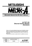
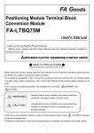
(1) LED Display
The display LEDs indicate the data communication status,
operating status, error status of the QC24N.
RUN
ERR. C.R/W
C/N
NEU.
P/S
ACK.
PRO. NAK
SIO SD.W.
SD
RD
ERROR
SW.E. ERR.
NEU. C/N
ACK. P/S
PRO.
NAK
SD.W. SIO
SD
RD
CH1
CH2
4
Brown
LED Name
Meaning of
LED Display
RUN
Normal
Operation
ERROR
Error batch
SD
RD
C.R/W
SW.
E.
Display
select
switch
STS
side
NEU.
ACK.
NAK
LED OFF
(OFF)
Normal
Abnormal
Any of ERR. error, C/N
error, P/S error, PRO
Normal
error, SIO error occur
Blinks during data
CH send
Not
sent
transmission
status
CH receive Blinks during data
Not
received
reception
status
Communicating Blinks during PC communications
with PC
(when not communicating is OFF)
Switch setting
Switch setting error
Normal
error
Transmission
Command
CH neutral
sequence initial status message
status
(Waiting to receive
receive
command messages) completed
CH [Normal
After [Abnormal
After
[Normal
End]
End]
End]
transmitted
transmission
transmitted
CH
After
[Abnormal
End]
After
[Normal
[Abnormal End]
transmitted
end] transmitted
transmission
Send wait
SD.W. status
CH error
ERR. occurrence
Display
select
switch
ERR.
side.
LED ON
(ON/BLINK)
When data send wait
After start of
state generated
transmission
Switch setting error,
mode switching error,
Normal
send error, receive
error, on-demand error
CH and PC
CPU
C/N communications
*2
result
CH
P/S parity/sum
Parity/sum check error
check error
CH protocol Communications
PRO. error
protocol error
Overrun, framing error
When receive data
SIO CH SIO
purged because OS
error
area is full.
Initial
Status
of LED
Related Protocol
Dedicated
Bidirectional
Non
procedure
ON
OFF
OFF
OFF
OFF
OFF
*1
OFF
OFF
OFF
OFF
Normal
OFF
Normal
OFF
Normal
OFF
Normal
OFF
Normal
OFF
*1 The displayed content is valid when the dedicated protocol is set as
the target interface.
The LED is off when other than the dedicated protocol is set as the
target interface.
*2 The LED is turned on when an illegal communication request is
received from an external device, or an error occurs while
accessing the PC CPU.
5
(2) Station number switch setting
Set the station number so that external devices can specify the PC
as the target of access during data communication via the
dedicated protocol.
Station Switch
Details
Station No.
23
90 1
23
X1
456
78
78
X 10
456
Description
(1) Station number of the local QC24N is set from 0 to 31.
(Do not set a station number over 32.)
(2) X10 sets the station number 10 digit.
(3) X1 sets the station number 1 digit.
(4) Make sure that the station number setting does not
overlap with another QC24N, etc., on the same
network.
(5) Not necessary to set the station numbers in connect
order. Station numbers can also be skipped.
(The factory setting is [00].)
90 1
(3) Mode switch setting
Set data communication functions for each interface.
Mode Mode
Switch Switch
Details No.
Setting Contents
When CH1 and CH2 operation is linked:
0
Mode
23
67
89
CD
AB
45
CH
1
2
3
4
5
6
7
8
to
D
E
F
Set CH1 to 0
Set CH2 to 1 to 6
When CH1 and CH2 operate independently: Setting impossible.
Format 1
ASCII
Format 2
Dedicated protocol
mode
Format 3
Format 4
Binary mode
Format 5
Non procedure protocol
Bidirectional protocol
Setting impossible
ROM/RAM/switch test
Self loopback test
(The factory setting is "1")
Point
Always set "1" to "7" for the mode setting switch on the interface side
that is not connected to the external device.
6
01
EF
(4) Transmission specifications switch setting
Set specifications for the communication with the data
communication destination device, as well as other items.
Switch
Details
Switch
CH1 CH2
Setting Item
Switch State
OFF
ON
SW1
Operation setting
SW2
Data bits setting
Parity bit enable
/disable setting
Even parity
/odd parity setting
Stop bit setting
Sum check enable
/disable setting
Write during RUN
enable/disable
setting
SW3
SW4
SW5
SW6
SW7
SW8
Setting change
enable/disable
SW9
to
SW12
Transmission
speed setting
Independent Linked
operation
operation
7 bits
8 bits
Disable
Enable
Odd
Even
1 bit
2 bits
Disable
Enable
Disable
Enable
Disable
(prohibit)
(*1)
Enable
(allow)
Notes
Set CH1 to OFF.
CH2 can be set to
ON/OFF.
Parity bit not included.
When set to Enable, the
setting of SW4 is effective.
Effective only when Parity
Bit Enable is selected.
Dedicated protocol,
bidirectional protocol
Dedicated protocol
Sets mode switching and
EEPROM write
allow/prohibit.
Can be set as long as the
total of CH1 and CH2 is
within 115200 BPS.
(The factory settings are all OFF.)
*1
The data transmission speeds allowed to set are as follows:
Transmission speed (unit: BPS)
SW09
Switch SW10
SW11
SW12
300
600 1200 2400 4800 9600 19200 38400 14400 28800 57600 115200
OFF
OFF
OFF
OFF
ON
OFF
OFF
OFF
OFF
ON
OFF
OFF
ON
ON
OFF
OFF
OFF
OFF
ON
OFF
ON OFF ON OFF ON OFF ON
OFF ON ON OFF OFF ON
ON
ON ON ON OFF OFF OFF OFF
OFF OFF OFF ON ON ON
ON
* Settings other than above are not accepted.
Point
The transmission specification setting switch shown above is located
on the modules whose hardware versions are B or later.
Even though the switch layout has been changed, the function set
by each switch and the corresponding ON/OFF position remain the
same as those of the conventional model.
7
4. Mounting and Installation
This section describes the handling precautions and installation
environment common to all the modules when handling the QC24N
from unpacking to installation.
Refer to the User's Manual of the PC CPU module used for a detailed
description of mounting and installation of the module.
4.1
Handling Precautions
This section describes the module handling precautions.
(1) The module case is made of plastic. Be sure not to drop it or
subject it to strong vibration.
(2) Tighten the module installation screws within the following
tightening torque range.
Screw
RS-422/485 terminal block terminal screws
(M3.5 screws)
Module installation screws (M4 screws)
Tightening Torque Range
59 to 88N • cm {6 to 9kgf • cm}
(5.2 to 7.8lb • inch)
78 to 118N • cm {8 to 12kgf • cm}
(6.9 to 10.4lb • inch)
RS-422/485 terminal block installation screw 39 to 59N • cm {4 to 6kgf • cm}
(M3 screws)
(3.5 to 5.2lb • inch)
RS-232C connector installation screw
19 to 24N • cm {1.9 to 2.4kgf • cm}
(M2.6 screws)
(1.7 to 2.0lb • inch)
4.2
Installation Environment
Do not install the Q2AS series PC in the following environments.
(1) Where the ambient temperature exceeds the 0 to 55°C range.
(2) Where the ambient humidity exceeds the 10 to 90% RH range.
(3) Where condensation is produced by sudden temperature changes.
(4) Where corrosive or combustible gas is present.
(5) Where dust, iron powder and other conductive powder, oil mist,
salt, or organic solvents are prevalent.
(6) In direct sunlight.
(7) Where a strong electric or magnetic field is generated.
(8) Where vibration and shock may be transmitted directly to the
module.
8
5. External Wiring
5.1
Connecting RS-232C Line
The standard connection procedure for RS-232C line is explained
below.
1
2
3
4
5
6
7
8
9
Pin
No.
Signal
Code
Signal Name
1
2
3
4
5
6
7
8
CD
RD (RXD)
SD (TXD)
DTR (ER)
SG
DSR (DR)
RS (RTS)
CS (CTS)
Receive carrier detection
Received data
Send data
Data terminal ready
Signal ground
Data set ready
Send request
Send enabled
*1
Signal Direction
(QC24N (*1)
External Device)
A1SJ71QC24N
: CH1 side
A1SJ71QC24N-R2 : CH1 side/CH2 side
The following type of the RS-232C connector is used. The counter
connector must match this connector.
9-pin D-sub (female) screw type
17L-10090-27-D9AC (DDK ELECTRONICS LTD)
(1) An example of connecting to an external device which is capable of
turning ON/OFF the CD signal (pin 1)
(Full-duplex/Half-duplex communications)
QC24N Side
Signal Name
Pin No.
CD
1
RD (RXD)
2
SD (TXD)
3
DTR (ER)
4
SG
5
DSR (DR)
6
RS (RTS)
7
CS (CTS)
8
Connection and Signal
Direction (Example)
9
External Device
Signal Name
CD
RD (RXD)
SD (TXD)
DTR (ER)
SG
DSR (DR)
RS (RTS)
CS (CTS)
(2) An example of connecting to an external device which is not
capable of turning ON/OFF the CD signal (pin 1)
(a) An example for DC code control or DTR/DSR control
(Full-duplex communications)
QC24N side
Signal Name
Pin No.
CD
1
RD (RXD)
2
SD (TXD)
3
DTR (ER)
4
SG
5
DSR (DR)
6
RS (RTS)
7
CS (CTS)
8
Connection and Signal
Direction (Example)
External Device
Signal Name
CD
RD (RXD)
SD (TXD)
DTR (ER)
SG
DSR (DR)
RS (RTS)
CS (CTS)
(b) An example for DC code control (Full-duplex communications)
QC24N Side
Signal Name
Pin No.
CD
1
RD (RXD)
2
SD (TXD)
3
DTR (ER)
4
SG
5
DSR (DR)
6
RS (RTS)
7
CS (CTS)
8
Connection and Signal
Direction (Example)
External Device
Signal Name
CD
RD (RXD)
SD (TXD)
DTR (ER)
SG
DSR (DR)
RS (RTS)
CS (CTS)
(3) Precaution when performing connections
1) Handle the FG signal and the shield of the connection cable in
the following manner.
Connection Method
Remark
FG signal Connect to the
Do not short circuit the FG
connector cabinet area
signal and the SG signal of the
on the QC24N side.
connection cable.
Shield
Connect to the FG
When the FG signal and the
SG signal are internally
terminal on the external
device side or
connected on the external
connector cabinet area
device side, do not connect the
on the QC24N side.
FG signal to the QC24N.
10
2) When a normal data communication cannot be performed
because of external noise even though the wiring has been
made as above, perform the wiring as follows:
Connect between the FG terminal of the external device
side and connector cabinet area of the QC24N side with
the shield of the connection cable.
On the external device side, however, follow the
instruction manual of the external device.
Connect each signal other than SG of the connection
cable by paring up with SG.
(QC24N side)
(Partner device side)
FG
SD
Shield
RD
RD
SD
DSR
DTR
DTR
DSR
:
:
SG
:
SG
Connector
cabinet area
3) Do not connect a RS-422 device to the RS-232C interface.
If a RS-422 device is connected, the RS-422 interface
hardware on the connected device will be damaged, and
communication will be disabled.
Point
When using QC24N's modem functions, use the RS-232C cable
supplied with the modem/TA or a cable specified by the modem/TA
for connection between the QC24N and the modem/TA.
11
5.2
Connecting RS-422/485 Line
The standard connection procedure for RS-422/485 line is explained
below.
Signal
Code
SDA
SG
SDB
(FG)
RDA
(FG)
RDB
SDA
SDB
RDA
RDB
SG
(FG)
(FG)
Signal Name
Signal Direction
(QC24N (*1)
External Device)
Send data (+)
Send data (-)
Received data (+)
Received data (-)
Signal ground
Frame ground
Frame ground
*1
A1SJ71QC24N
: CH2 side
A1SJ71QC24N-R2 : (None)
(Function block diagram for the QC24N side)
SDA
Send data
+
-
SDB
+
RDA
-
RDB
Received data
12
Point
If the QC24N is the first or last station on the RS-422/485 line,
connect a terminal resistor of the following specifications to the RS422/485 interface.
Data communication will be disturbed if a terminal resistor is not
used.
• For RS-422 communication .................... 330 Ω, 1/4 W
• For RS-485 communication .................... 110 Ω, 1/2 W
(1) When a QC24N is connected to each external device, connect a
terminal resistor between RDA and RDB.
(2) When the relationship between the numbers of connected
external devices and QC24Ns is 1:n, connect terminal resisters
between SDA and SDB and between RDA and RDB.
(3) When the relationship between the numbers of connected
external devices and QC24Ns is m:n, connect a terminal
resister between RDA and RDB.
The R in the wiring diagram below indicates the connection of a
terminal resistor.
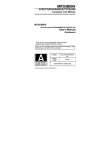
(1) Example of connecting external devices and QC24N by 1:1
R
External Device
Signal Name
RDA
RDB
SDA
SDB
RSA
RSB
CSA
CSB
Connection and Signal
Direction (Example)
SG
FG
QC24N Side
Signal Name
SDA
SDB
RDA
RDB
SG
(FG)
(FG)
13
R
(2) Example of connecting external devices and QC24N by 1:n
1) Connecting external devices and QC24N using RS-232C
External device
RS-232
Station 0 QC24N
R
SD
SD
R
RD
RS-485
Station 1 QC24N
RS-485
Station n QC24N
SDA
SDA
SDB
SDB
SDA
SDB
RDA
RDA
RDA
RDB
RDB
RDB
RD
SG
SG
SG
FG
FG
FG
(CH1)
(CH2)
R
R
2) Connecting external devices and QC24N using RS-422
External device
RS-422
Station 0 AJ71QC24N-R4
RS-485
R
SDA
SDA
SDB
SDB
RDA
RDA
RDB
RDB
R
(CH1)
Station 1 QC24N
RS-485
Station n QC24N
SDA
SDA
SDA
R
SDB
SDB
SDB
RDA
RDA
RDA
RDB
RDB
RDB
SG
SG
SG
FG
FG
FG
R
R
(CH2)
3) Connecting external devices and QC24N using RS-485
External
device
R
R
RS-485
Station 0 QC24N
RS-485
Station 1 QC24N
RS-485
Station n QC24N
SDA
SDA
SDA
SDA
SDB
SDB
SDB
SDB
RDA
RDA
RDA
RDA
RDB
RDB
RDB
RDB
SG
SG
SG
SG
FG
FG (CH2)
FG
FG
14
R
R
(3) Example of connecting external devices and QC24N by m:n
* Connecting external devices and QC24N using RS-485
External
device
External
device
SDA
SDB
RDA
RDB
SDA
SDB
RDA
RDB
SG
FG
SG
FG
Station 0
QC24N
Station 1
QC24N
Station n
QC24N
SDA
SDB
RDA
RDB
SDA
SDB
RDA
RDB
SDA
SDB
RDA
RDB
SG
FG
SG
FG
SG
FG
Point
In case of connecting external devices and QC24N by m:n, refer to
Section 5.1 for an example of connecting external devices and
QC24N using RS-232C.
(4) Countermeasure for data receive errors at the external device with
RS-422 and RS-422/485 connections
During the data communication with external devices via QC24N
RS-422/485 interface , if the external device receives an error data,
install pull-up and pull-down resistors to the external device side
(about 4.7kΩ, 1/4 W as a reference of resistor value).
Installation of pull-up and pull-down resistors will prevent a data
receive error.
RDA
RDB
4.7k
1/4W
+
Terminal
resistor
4.7k
Received data
-
1/4W
External device
15
Point
When there is a pull-up or pull-down resistor at the external device,
erroneous data is not received.
Remark
The following describes the case when a pull-up or pull-down
resistor is not installed to the external device.
1) When no station is sending, the send line becomes high
impedance and noise, etc. may cause the send line to change
and the external device to receive erroneous data.
In this case, there is probably a parity error or framing error.
Therefore, skip the erroneous data.
2) Since the first data during data reception is fixed in the
following cases, also skip the receive data until the head data
is received.
When using a dedicated protocol for data communication,
the user selects the first data according to the mode and
format used.
When performing data communication using user frames
with Non procedure protocol, the user selects the first data
according to the user frames registered in the QC24N.
(5) Connection precautions
1) When connecting the QC24N SG and FG signals to the
external device, connect them according to the specifications
of the external device.
2) Connect the shield of the connection cable to either of the FG
signals of the connected device.
3) When a normal data communication cannot be performed
because of external noise even though the wiring has been
made as above, perform the wiring as follows:
16
Connect between the FG of both stations with the shield of
the connection cable.
On the external device side, however, follow the
instruction manual of the external device.
Connect the (FG) of the QC24N side to the FG terminal at
the power supply module of the station which has a
QC24N installed, or to the FG terminal of the control panel
on which the QC24N PC is installed.
Connect nnA and nnB of each signal in the connection
cable as a pair.
(QC24N side)
Shield
(Partner device side)
RD
SDA
SDB
RD
RD
SDA
SDB
RD
SG
SG
(FG)
FG
(FG)
To the FG terminal of the power module of the QC24N loading station,
or to the FG terminal of the control panel
Point
(1) In the description of the setting and connection of the terminal
resistor in this section, if the RS-232C RS-422 converters,
etc. are used on the stations on both ends of the network, the
setting and connection of the terminal resistor is necessary on
the converter side.
(2) The devices connected to the QC24N RS-422/485 interface
must be unified with either RS-422 or RS-485 for 1:n and m:n
connections.
17
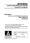
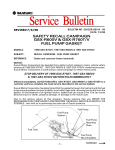
6. External Dimensions
(A1SJ71QC24N (-R2))
A1SJ71QC24N
ERROR
SWE. ERR.
C/N
NEU.
P/S
ACK.
NAK PRO.
SD W SIO
SD
RD
RUN
ERR. C R/W
C/N
NEU.
P/S
ACK.
PRO. NAK
SIO SD W
SD
RD
CH1
CH2
DISPLA
STS
ERR.
10
1
23
23
456
901
901
CH1
130
(5.12)
45
34 5
23
F01
SW
67
89
CD E
AB
2
CH2
89
CD E
AB
67
MODE
F01
STATION NO.
78
78
456
1
2
3
4
5
6
7
8
9
10
11
12
ON
CH2RS-422/485
SDA
SG
SDB
R1
(FG)
r1
RDA
(FG)
RDB
CH1 RS-232-C
A1SJ71QC24N
R2
6.5
(0.26)
93.6
26.2
34.5
(3.69)
(1.03)
(1.36)
mm (inch)
R1 (bend radius near terminal board) : Cable diameter × 4
R2 (bend radius near connector )
Cable diameter × 4
r1 (bend radius near crimp terminal)
Can be connected within
the range over which
bending is not excessive
* Except for the interface section, the A1SJ71QC24N (-R2) outline
dimensions of all two models are the same.
The illustration above shows the outline dimensions of the
A1SJ71QC24N.
18
The United States
Canada
United Kingdom
Germany
Taiwan
Hongkong (& China)
Singapore (& Malaysia)
Thailand
Australia
Republic of South Africa
Mitsubishi Electronics America, Inc., (Industrial Automation Division)
800 Biemann Court, Mt. Prospect, IL 60056.
Phone : (708) 298-9223
Mitsubishi Electric Sales Canada, Inc., (Industrial Automation
Division)
4299 14th Avenue, Markham, Ontario L3R OJ2
Phone : (416) 475-7728
Mitsubishi Electric UK Ltd., (Industrial Sales Division)
Travellers Lane, Hatfield, Herts., AL10 8XB
Phone : (0707) 276100
Mitsubishi Electric Europe GmbH, (Industrial Automation Division)
Gothaer Strasse 8, Postfach 1548, D-4030 Ratingen 1
Phone : (02102) 4860
Setsuyo Enterprise Co., Ltd.,
(106) 11th FI., Chung-Ling Bldg., 363, Sec. 2, Fu-Hsing S. Rd.,
Taipei,
Taiwan. R.O.C.
Phone : (02) 732-0161
Ryoden International Ltd., (Industrial & Electrical Controls Division)
10/F., Manulife Tower, 169 Electric Rd., North Point, Hong Kong.
Phone : 8878870
MELCO Sales Singapore Pte. Ltd., (Industrial Division)
307 Alexandra Rd. #05-01/02, Mitsubishi Electric Bldg., Singapore
0315.
Phone : 4732308
F.A. Tech Co., Ltd.,
1138/33-34 Rama 3 Rd., Yannawa, Bangkok 10120.
Phone : (02) 295-2861-4
Mitsubishi Electric Australia Pty. Ltd., (Industrial Controls Division)
348 Victoria Rd., Rydalm ere, N.S.W. 2116.
Phone : (02) 684-7200
M.S.A. Manufacturing (Pty) Ltd., (Factory Automation Division)
P.O. Box 39733, Bramley, Johannesburg 2018.
Phone : (011) 444-8080
HEAD OFFICE: MITSUBISHI DENKI BLDG MARUNOUCHI TOKYO 100 TELEX: J24532 CABLE MELCO TOKYO
NAGOYA WORKS: 1-14, YADA-MINAMI 5, HIGASHI-KU, NAGOYA, JAPAN
When exported from Japan, this manual does not require application to the
Ministry of International Trade and Industry for service transaction permission.
Specifications subject to change without notice.
Printed in Japan on recycled paper.