1
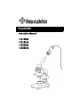
PupilCAM
Instruction Manual
Instruction Manual
1401KRM
1401KRM
1401KEM
1401KEM
1401KRN
1402KRM
1401KEN
1402KEM
1401KR
1401KE
Thank you for your purchase of a Ken-A-Vision PupilCAM! This high-resolution
camera captures microscopic images and displays them on your computer
with full screen viewing. The pre-attached cable provides a direct interface to
your equipment. It’s ready to go, no assembly required!
Connecting The USB Cable to Your Computer
Prior to connecting the USB cable, you must first install the supplied software.
Pre-attached cabling makes it easy to connect the USB cable to you computer.
Simply insert the rectangular end of the USB cable to the USB port of your
computer.
Note: The USB port will supply ample power to the the PupilCAM®. No power
additional power supply is required.
Connecting to a Microscope
The PupilCAM® is designed exclusively to work with a microscope (compound
or stereoscope). A variable eyepiece adapter is built-in to the camera.
Gently twist the PupilCAM® as you push it down onto the microscope.
1401KRM/1402KRM models feature a rubber adapter that fits snuggly over
28mm microsocope eyepieces.
1401KEM/1402KEM models feature a built-in 10x eyepiece that is inserted
into 23mm microsocope eyepiece tubes or 30mm eyepiece tubes with the
included adapter.
All focusing should be done using the microscope focus knobs.
2
To learn more about other Ken-A-Vision products
and services please visit our website at
www.ken-a-vision.com
Or call
1-816-353-4787
3
Information To The User:
Changes or modifications not expressly approved by the party responsible for
compliance could void the user’s authority to operate the equipment.
Note: This equipment has been tested and found to comply with the limits for a
Class B digital device, pursuant to part 15 of the FCC rules. These limits are
designed to provide reasonable protection against harmful interference in a
residential installation. This equipment generates, uses and can radiate radio
frequency energy, and if not installed and used in accordance
with instructions, may cause harmful interference to radio communication.
However, there is no guarantee that interference will not occur in a particular
installation.
If this equipment does cause harmful interference to radio reception which can
be determined by turning the equipment off and on, the user is encouraged to
try to correct the interference by one or more of the following
measures: Reorient or relocate the receiving antenna and/or increase
the separation distance between the equipment and the receiver, and/
or connect equipment into an outlet on a circuit different from that which the
receiver is connected; and/or consult your dealer or experienced radio/tv
technician for help.
Ken-A-Vision reserves the right to make design improvements and other changes in accordance with the
latest technology. There is no obligation to make changes in products already manufactured. Patents
Pending Copyright 2009 Ken-A-Vision Corporation
5615 Raytown Road • Kansas City, MO 64133 U.S.A.
Tel.: 816-353-4787 • Fax: 816-358-5072
email:[email protected] • www.ken-a-vision.com
INS-PC