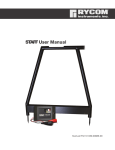
1
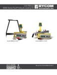
User Manual
8879v4 Locating Series
Manual Covers
8879v4 -10watt
8880v4 - 10watt
Manual Part # 030-00107-00
Copyright
Copyright © 2015 RYCOM Instruments, Inc. All rights reserved.
No part of this manual may be reproduced, copied, modified or adapted, without the prior written
consent of the RYCOM Instruments, Inc.
Please feel free to contact RYCOM Instruments, Inc. to request permission for reproduction and use
of this manual for training purposes.
800.851.7347
www.rycominstruments.com
Table
of
Contents
General Information
Introduction . . . . . . . . . . . . . . . . . . . . . . . . . . . . . . . . . . . . . . . . . . . . . . . . 2
Disclaimer of Liability . . . . . . . . . . . . . . . . . . . . . . . . . . . . . . . . . . . . . . . . 2
Important Notices . . . . . . . . . . . . . . . . . . . . . . . . . . . . . . . . . . . . . . . . . . . 2
Prepare for Use . . . . . . . . . . . . . . . . . . . . . . . . . . . . . . . . . . . . . . . . . . . . . 3
Register Extended Warranty . . . . . . . . . . . . . . . . . . . . . . . . . . . . . . . . . . 3
Transmitter Controls and Indicators . . . . . . . . . . . . . . . . . . . . . . . . . . . . 4
Direct Connect . . . . . . . . . . . . . . . . . . . . . . . . . . . . . . . . . . . . . . . . . . . . . 5
Flexicoupler Connection . . . . . . . . . . . . . . . . . . . . . . . . . . . . . . . . . . . . . 5
Inductive Connection . . . . . . . . . . . . . . . . . . . . . . . . . . . . . . . . . . . . . . . 6
Blind Search . . . . . . . . . . . . . . . . . . . . . . . . . . . . . . . . . . . . . . . . . . . . . . . . 6
Selecting the Tracing Signal . . . . . . . . . . . . . . . . . . . . . . . . . . . . . . . . . . 7
Receiver Controls and Indicators . . . . . . . . . . . . . . . . . . . . . . . . . . . . . . 8
Locating the Cable or Pipe . . . . . . . . . . . . . . . . . . . . . . . . . . . . . . . . . . . 9
Selecting the Locating Mode . . . . . . . . . . . . . . . . . . . . . . . . . . . . . . . . . 9
Peak Locating Mode . . . . . . . . . . . . . . . . . . . . . . . . . . . . . . . . . . . . . 9-10
Null Locating Mode . . . . . . . . . . . . . . . . . . . . . . . . . . . . . . . . . . . . . . . . 10
Left/Right Auto-Gain Mode . . . . . . . . . . . . . . . . . . . . . . . . . . . . . . . . . . 11
Absolute Signal Strength . . . . . . . . . . . . . . . . . . . . . . . . . . . . . . . . . . . . 11
Gain Change Indication . . . . . . . . . . . . . . . . . . . . . . . . . . . . . . . . . . . . 11
Passive 50/60 Hz Locating . . . . . . . . . . . . . . . . . . . . . . . . . . . . . . . . . . . 12
Passive Radio Frequency Locating . . . . . . . . . . . . . . . . . . . . . . . . . . . 12
Passive Rectifier CP Locating . . . . . . . . . . . . . . . . . . . . . . . . . . . . . . . . 12
Push Button Depth . . . . . . . . . . . . . . . . . . . . . . . . . . . . . . . . . . . . . . . . . 13
Current Measurement . . . . . . . . . . . . . . . . . . . . . . . . . . . . . . . . . . . . . . 13
Depth Measurement 45 Degree Angle Method . . . . . . . . . . . . . . . . 14
Tilted Magnetic Field Identification . . . . . . . . . . . . . . . . . . . . . . . . . . . 14
Locating a Sonde . . . . . . . . . . . . . . . . . . . . . . . . . . . . . . . . . . . . . . . . . . 15
Sonde Depth Measurement . . . . . . . . . . . . . . . . . . . . . . . . . . . . . . . . . 16
STAFF Fault Finder Controls . . . . . . . . . . . . . . . . . . . . . . . . . . . . . . . . . . 17
Fault Locating . . . . . . . . . . . . . . . . . . . . . . . . . . . . . . . . . . . . . . . . . . . . . 18
8879v3 Transmitter Specifications . . . . . . . . . . . . . . . . . . . . . . . . . . . . . 22
8879v3 Receiver Specifications . . . . . . . . . . . . . . . . . . . . . . . . . . . . . . . 23
Factory Service . . . . . . . . . . . . . . . . . . . . . . . . . . . . . . . . . . . . . . . . . . . . 24
Warranty . . . . . . . . . . . . . . . . . . . . . . . . . . . . . . . . . . . . . . . . . . . . . . . . . . 24
Parts List . . . . . . . . . . . . . . . . . . . . . . . . . . . . . . . . . . . . . . . . . . . . . . . . . . 25
800.851.7347
www.rycominstruments.com
Introduction
Congratulations on the purchase of your new RYCOM 8879v3 Series Cable, Pipe & Fault Locator. The
8879v3 Locator is specially designed to detect pipes, sondes & buried cables. This device may detect
buried power cables, CATV cables, gas and water pipes, sewer lines, telecommunication lines, fiber
optic cables with sheath, sondes, inspection camera transmitters. You have chosen a quality product
that is designed for years of field use without the need for annual or periodic calibration and service.
The basic principle of the locator's operation is as follows:
The Transmitter emits a signal to a conductive cable or pipe. The Receiver detects the
electromagnetic field that is generated by the transmitted signal. You can locate the relative
position of the buried utility by following the tracing signal.
For safely & to help ensure the best locating results, please read & understand the manual in its
entirety before using the product.
Disclaimer Of Liability
RYCOM Instruments, INC shall not be liable to Distributor, Reseller, or any other person for any incidental, indirect, special, exemplary or consequential damages, or injury of any type whatsoever, and
caused directly or indirectly by Products sold or supplied by RYCOM INSTRUMENTS, INC.
Important Notices
WARNING!
Failure to follow these warning could result in serious injury or death.
Only persons qualified and trained to operate cable & pipe locators may operate this equipment.
Follow appropriate safety procedure, your companies policies and applicable safety codes and/or
laws.
WARNING!
Do not connect to utilities, cables or pipes without authorization and training.
Use tool only for intended purpose as described in this manual
Do not expose tool to rain or moisture.
WARNING!
Do not expose to hazardous chemicals, hazardous gas or explosive environment.
WARNING!
SHOCK HAZARD - Lethal voltages may be present at the transmitter's output. Turn off transmitter before
touching test lead or any un-insulated conductor. Make connection to ground and target conductor
before turning on transmitter.
WARNING!
SHOCK HAZARD - Do not connect to live voltage or active utility lines. De-energize any circuits in or
around the work area.
WARNING!
This tool is designed to detect electromagnetic field emitted from cables and buried metallic utilities.
There are buried cables, pipes, and utilities this instrument CANNOT detect.
WARNING!
LOCATING is not an exact science. The only certain way to be sure of the existence, location, or depth
of buried utilities is to carefully expose (dig up) the utility.
800.851.7347
www.rycominstruments.com
Prepare
for
Use
Unpack your new 8879v4 Locator . Make sure there is no shipping damage and all the parts are
included.
Locate the battery compartment on the back of the of the Receiver. Open the compartment using a
Phillips screwdriver. Install the six Duracell® “C” batteries as marked.
For an alkaline transmitter, locate the battery compartment on the bottom of the of the Transmitter.
Open the compartment using a Phillips screwdriver. If using an 8879 style transmitter install twelve
Duracell® “D” batteries as marked.
For rechargeable transmitters, please charge the transmitter for at least 5 hours before use.
Note: For longer battery life and reliable operation under adverse conditions, use only Duracell®
alkaline batteries.
Register Extended Warranty
By registering your unit online at http://www.rycominstruments.com/extended.html within one month
(30 Days) of purchase RYCOM will extend the warranty period from one year to 4 years.
This instrument is under warranty for one year from the date of delivery against defects in material
and workmanship (EXCEPT BATTERIES). We will repair or replace products that prove to be defective
during warranty period.
This warranty is void if, after having received the instrument in good condition, it is subjected to abuse,
unauthorized alterations or casual repair.
No other warranty is expressed or implied. The warranty described in this paragraph shall be in lieu of
any other warranty, including but not limited to, any implied warranty of merchantability or fitness for
a particular purpose. We are not liable for consequential damages.
800.851.7347
www.rycominstruments.com
Changing Preset Frequencies
The 8879 receiver operating frequencies are user programable and can be
changed at anytime through a quick selection process.
To selct the desired frequency set:
• Press and hold depressed the Power On Button.
• Pressing the Information Button will toggle through avaiable configurations. Repeat
pressing until u3 is displayed in the Frequency Indicator section of the LCD.
• Release the Power On Button and the unit will turn off.
• Press and hold depressed the Power On Button.
• Press the Frequency Button to toggle through the available frequencies.
• To select and store the desired frequency press the Information Button. The count
of the selected frequency will be displayed on the LCD.
• Continue to toggle through and select the desired frequencies,
• Releasing the Power On Button will save the selected frequencies for avaiability
during normal operation.
The 8879 transmitter operating frequencies are user programable and can be
changed at anytime through a quick selection process.
To selct the desired frequency set:
• Press and hold depressed the Power On Button.
• Pressing the Information Button will toggle through avaiable configurations. Repeat
pressing until u3 is displayed in the Frequency Indicator section of the LCD.
• Release the Power On Button and the unit will turn off.
• Press and hold depressed the Power On Button.
• Press the Frequency Button to toggle through the available frequencies.
• To select and store the desired frequency press the Information Button. The count
of the selected frequency will be displayed on the LCD.
• Continue to toggle through and select the desired frequencies,
• Releasing the Power On Button will save the selected frequencies for avaiability
during normal operation.
800.851.7347
www.rycominstruments.com
815 Hz
Transmitter Controls & Indicators
LOADING
8 kHz
I/O
I
Output Level
Indicator
82 kHz
Load Rate
Indicators
Output Signal
Level Control
DFF
F.1
F.2
mA
v
I/O
Tx Output Jack
CAUTION
Lethal Voltages May Be Present
High Power
Output
Indicator
LOADING
8 kHz
kM
I
Relative
Resistance, Volt,
Current
8878
815 Hz
kHz
TX OUTPUT
Frequency
Selector
82 kHz
Battery Condition
Indicator
PLACE ARROWS ALONG CABLE PATH
FOR INDUCTIVE MODE
Signal Information
Selector
Power On & Off
TX OUTPUT JACK
The Red/Black Cord, Coupler and Flexicoupler connects here to create a circuit on the buried utility.
FREQUENCY SELECTOR
This button toggles through the available frequencies. The selected frequency is displayed on the
LCD. When dual frequency transmission options are selected, indicated by the F1 & F2 icons to the
right large numeric segments, the frequencies will flash from one to another.
To activate DFF Fault Finding mode, press and hold for 5 seconds. When release the transmitter will be
in DFF mode and the DFF icon will appear on the LCD.
LOAD INDICATOR (visual & audible)
The Load Indicator symbol flashes to indicate signal output.
The quick triple beep audible tone indicates the circuit is open and no signal is being transmitted.
A steady continuous beep indicates a closed circuit and signal is transmitted . When the indicator
blinks 4 times per second, it is indicating a nearly short circuit. When the indicator blinks 1 time every
10 seconds, it is indicating a nearly open circuit.
OUTPUT SIGNAL LEVEL CONTROL
The OUTPUT SIGNAL LEVEL CONTROL adjusts the power output from the Transmitter. There are 5 selections on the standard power setting and 5 selections on the HPO setting. The standard power output
maximum is 30volts. In the HPO setting the maximum voltage is 130volts. Holding down the Output
Signal Level button for 3 Seconds will activate the High Power Output mode.
WARNING!
High Power Output is a SHOCK HAZARD - Lethal voltages at the transmitter's output. Turn off transmitter
before touching test lead or any un-insulated conductor. Make connection to ground and target
conductor before turning on transmitter.
SIGNAL INFORMATION SELECTOR
The unit can display the relative resistance, current and voltage of the transmitted signal. The resistance is based on the feed back from the selected frequency and is not an actual impedance
meter. The selections can be toggled by pressing the SIGNAL INFORMATION button.
800.851.7347
www.rycominstruments.com
Direct Connection
CAUTION
DO NOT CONNECT TO LIVE OR
ENERGIZED POWER CABLES
Direct Connection is the most reliable method of signal application. This method is relatively free
of interference. The greatest amount of signal strength can be achieved by this method. Low,
mid, and high frequency may be used. The far end of the utility must be grounded.
Connect the Red Test Cord to an existing ground point or an exposed metallic section of the utility
. Place the Ground Rod approximately 10 feet from this point, at an angle of 90º to the buried
cable or pipe. Push the Ground Rod into the ground 8 to 10 inches. Connect the Black Test Cord
to the Ground Rod.
Plug the Red/Black Test Cord into the TX OUTPUT JACK. Press the FREQUENCY Button for 815 Hz,
8 kHz, 33 kHz or 82 kHz. The Power Output Indicator and the Frequency light of the chosen frequency will light up.
TRANSMITTER
BLACK
RED
BURIED CABLE
Coupler & Flexicoupler Connection
The optional Flexicoupler and Hard Coupler are very easy to use, and services do not have to
be interrupted. The operation range is shorter than for Direct Connection methods. The tracing
signal can be affected by neighboring cables and pipes. The Red/Black Test Cord or the Ground
Rod are not needed for this method.
Successful coupler operation requires an insulated conductor that is grounded on both near and
far ends.
Loop the Flexicoupler around the cable and connect the two ends, or clamp the Hard Coupler
around the cable. It is important to connect the coupler around the cable needing to be traced.
Connect the coupler around the wire closer to the outgoing cable not near the system ground.
The result will be a stronger signal. By connecting near the grounding, the range will also be
shorter, and difficulty may arise determining one cable from another.
Plug the Coupler into the TX OUTPUT JACK.
Some couplers are frequency specific others can operate on any frequency from 8kHz to 82kHz.
TRANSMITTER
FLEXICOUPLER
BURIED CABLE
800.851.7347
www.rycominstruments.com
Inductive Connection
This method is convenient to use, and services are not interrupted. No test cords or connections
are needed. The cable or pipe must have good insulation or non-conductive coating, or the
operating range will be short.
Turn the Transmitter ON. Select 33kHz through 478 kHz. Place Transmitter on its side as close as possible to the path of the cable or pipe. Align the ARROWS on the SIDE OF THE TRANSMITTER in line
with the cable or pipe. First, locate the broad Transmitter Null, then move toward the expected
cable path while looking for the signal carried by the cable.
Start tracing the path with the Receiver 25 feet from the Transmitter. Search in the 90º zone as
shown above. Locate the cable or pipe, and follow the path. If the signal becomes weak, move
the Transmitter to a point 25 feet behind the last strong signal, and continue searching.
TRANSMITTER
25 Feet (7.5 Meters) Between Transmitter and Reciever
Blind Search
The Blind Search locating techniques is used if the operator is not aware if a buried utility exists.
Two people are needed for this technique. The Transmitter and the Receiver are Held 25 feet away
from each other. Each operator walks at the same speed keeping a distance of 25 feet from
each other. When the receiver gives an audio response, then a buried utility is present between
the Receiver and the Transmitter.
TRANSMITTER
RECEIVER
25 Feet (7.5 Meters) Between Transmitter and Reciever
RECEIVER
800.851.7347
www.rycominstruments.com
Selecting
the
Tracing Signal
The choice of 815 Hz, 8 kHz, 33kHz or 82 kHz Frequency is dependent on the conditions of the
locate.
The 815 Hz, 8 kHz, 33kHz and 82 kHz signals each have their advantages. It is recommended to
begin by using the 815 Hz signal, and continue as long as you are confident in the results. If the
signal is very weak try to adjust the connection or grounding. If there is no improvement in signal
then try 8 kHz. Repeat adjustments of ground and connection point again until switching to 33
kHz and then 82 kHz.
815 Hz (lower frequency) signal is usually preferred to the 8 kHz (mid-range frequency) and 82 kHz
(high frequency) signal, because it is much less susceptible to locating errors caused by nearby
cables or pipes. The 815 Hz locating range is also much longer than the 82 kHz signal. The 815 Hz
signal will not travel well through disconnected shield bonds or insulated pipe bushing.
8 kHz and 33kHz takes the best of both high and low frequency. This mid range frequency is not
very susceptible to bleed off or coupling, but it can jump impedance on the utility better than
the 815 Hz. It is still best to use 815 Hz, but 8 kHz is one of the most common frequencies used to
locate coaxial cable and telecom pairs.
The 82 kHz (higher frequency) is sometimes better than the 815 Hz (lower frequency) for locating sharp corners in cables or pipes. The 82 kHz signal is also better for “jumping” disconnected
shield bonds or grounds, or tracing signal may indicate one of these characteristics. The locating
range is quite short for the 82 kHz signal so the Transmitter must be repositioned more often during
the tracing operation. This frequency is also useful for applying a signal using the Flexicoupler or
the Hard Coupler.
800.851.7347
www.rycominstruments.com
8879v3 Receiver Controls & Indicators
DISPLAYS ABSOLUTE
SIGNAL STRENGTH
OR DEPTH
OPERATION MODE
Displays selected
operation available to model
MEASURES DEPTH
(+ Shift Key
MEASURES
CURRENT)
RELATIVE SIGNAL
STRENGTH BAR GRAPH
(single bar shows gain
setting)
ON/OFF BUTTON
DISPLAYS SELECTED
FREQUENCY
FREQUENCY SELECTOR
(+ Shift Key
toggles on/off
backlight)
MODE SELECTOR
(+ Shift Key
toggles volume)
ADJUSTS GAIN UP OR
DOWN
SHIFT KEY
Hold while selecting secondary key
functions
ON/OFF Button
The unit will load settings from previous usage. Automatic shut off after 10 minute of no use.
FREQUENCY Button
Toggles through available active and passive frequencies (model specific).
Note: Some frequencies are only avaiable in certain modes and some modes will only be
avaiable with certain frequencies.
MODE Button
Toggle through available mode (model specific). PEAK, PINPOINT PEAK, NULL, LEFT/RIGHT, ACC
(when an accessory is plugged in) DFF and SONDE locating modes.
To select SONDE mode press and hold MODE key for 5 seconds. When released the unit will
toggle to SONDE mode. Hold for 5 seconds to exit SONDE mode.
To select DFF mode used for Fault finding with an A-frame or for Direction Signal locate mode,
press and hold the MODE button for 10 seconds. Hold for 10 seconds to exit DFF mode.
DEPTH & CURRENT Button
DEPTH function will first momentarily display the depth mode (Line [LIN] or Sonde [SON]) and then
display depth measurement at the top of LCD.
NOTE: To change the Depth Measurement from English to Metric, hold the Frequency Key for
ten seconds. CURRENT measures the relative amount of transmitted current and is displayed at
the bottom of the LCD.
GAIN Button (Up or Down)
Adjusts the gain up or down. If the signal strength shows as “ --- ” on the display, pressing the
GAIN will automatically adjust to 85% on the scale display.
+
VOLUME (SHIFT Button + MODE Button)
Toggle volume through High, Medium, Low and Off.
+
BACKLIGHT (SHIFT Button + FREQUENCY Button)
Hold the SHIFT Key and press the CURRENT key to toggle on and off the back light.
800.851.7347
www.rycominstruments.com
Locating Modes
There is a variety of locating modes available in the 8879v3 unit. PEAK, PINPOINT PEAK, NULL LEFT/
RIGHT GUIDANCE, SONDE, DFF & ACC. To toggle through PEAK, PINPOINT PEAK & NULL simple
press the mode button. To toggle to SONDE mode hold the MODE button for 5 seconds and
release. DFF and ACC modes are only selectable when an appropriate accessory is plugged
into the accessory port in the handle of the receiver.
Peak Mode Locating
With the Receiver in a vertical position. Move the Receiver left to right across the path. When
the Receiver is directly above the cable or pipe, rotate the Receiver for a maximum signal. As
you move the Receiver away from the cable path, the meter reading (and audio frequency
response) will drop off.
If you rotate the Receiver while over the cable, a sharp NULL will identify the cable’s direction. It
is aligned with the flat side of the Receiver.
CABLE
PATH
MAXIMUM
RECEIVER
SIGNAL
800.851.7347
www.rycominstruments.com
CABLE
PATH
NULL SHOWS
CABLE
DIRECTION
Trace the path by walking away from the Transmitter at a moderate pace. Move the Receiver to
the left and right while walking, following the PEAK indications.
As you trace the path, the PEAK meter reading may slowly fade as you move away from the
Transmitter. Press and release the GAIN buttons as needed to compensate for changes in level
(higher or lower). One of the following may occur:
a) a junction where the signal divides and goes several directions.
b) a break in the cable or shield.
c) a change in the depth of the cable or pipe.
d) an insulated pipe fitting.
e) a slack loop of cable.
If you can no longer trace the path, even with the GAIN set to maximum, connect the Transmitter
to the far end of the path and trace back to the point where you lost the signal.
Mark the straight sections of the path every few feet. Mark sharp curves, loops, and cable
bundles every few inches. Sharp changes in the path cause the Receiver PEAK and NULL indications to behave differently than when tracing a straight path. Practice on the path that you
know has turns and laterals in it. This will help you to recognize the conditions within the field.
Null Mode Locating
Move the Receiver left to right across the cable path. When the Receiver
is directly above the cable or pipe, a NULL (lowest meter reading and lowest audio
tone) will occur. When moving the Receiver to left or right of the NULL point, the
meter reading will rise to a maximum point (PEAK). The audio tone will also be at its
highest pitch. When the Receiver is moved beyond the PEAK, the meter reading will begin to
fade.
Trace the path by walking away from the Transmitter at a moderate pace. Move the Receiver to
the left and right when walking, following the NULL indications.
Peak Mode
Receiver Max
Signal over cable
Buried cable
800.851.7347
(End view)
Null Mode
Receiver Min
Signal over cable
Buried cable
www.rycominstruments.com
(End view)
Left Right Auto Gain Directional Locating
In this mode the unit will display directional arrows to the conductor. The audio indicator will
provide a solid tone on one side of the conductor and a pulsed tone on the opposite side of
the conductor. When the unit is centered in the electromagnetic field the tone will null and the
depth will briefly display at the top of the LCD. This mode is gain independent.
Absolute Signal Strength
The 8879v3 Receiver provides the operator with a direct measurement of the Receiver’s signal
strength. The measurement is displayed with three numerical digits (ex: 485) located at the top
of the LCD display. The measurement range is from 0 to 999 indicating a very week signal (0) to
a very strong signal (999). Absolute Signal Strength is independent of the GAIN setting or meter
reading. It gives the operator information about the actual amount of signal being radiated
from the conductor and received by the Receiver.
Measuring Absolute Signal Strength at any time is done by reading the number at the top of the
LCD display. The Absolute Signal Strength will not be displayed if the meter reading is too high
or too low. Adjust the GAIN to move the meter reading to mid-scale. The numerical display will
change from ‘---’ to a valid measurement.
Absolute Signal Strength measurements are more sensitive to signal changes than the meter
display. PEAKS and NULLS can be more precisely pin-pointed. This measurement can also be
used to monitor signal loss as the conductor is being traced.
Gain Level Indication
The GAIN up and down buttons are used to increase and decrease the gain in small amounts.
If the meter reading is very low, pressing the GAIN up button will center the meter reading to
mid-scale. Likewise, if the meter reading is very high, pressing the GAIN down button will center
the meter reading to mid-scale.
800.851.7347
www.rycominstruments.com
Passive 50/60 Hz Locating
The 8879v3 Receiver is capable of locating power utility frequencies. This MODE is useful for locating underground primary and secondary power utilities. In certain circumstances, this MODE will
also locate water pipes, sewer lines, cable television, and telephone. The reason is that common electrical grounds are sometimes found among these various utilities. Select 50Hz or 60Hz
frequency on the Receiver. PINPOINT PEAK mode will automatically be selected as the preferred
method to locate the conductor in passive power mode.
This method is useful because of its speed and convenience. Start at a known reference point
and keep in mind that other conductors in the area may produce this same locating signal.
The Transmitter is not required to locate in this mode.
Note: The unit of depth measurement determines the selection of either 50Hz or 60Hz passive
mode. The unit is configured for 50Hz when in Metric Measurement mode and 60Hz when in
English Measurement Mode. To change unit of measurement press and hold the frequency button for 10 seconds, when released the unit will toggle measurement units.
Passive Radio Frequency Locating
The 8879v3 Receiver is capable of passively locating metallic utilities where radio frequencies
have coupled to the utility. This mode is useful for sweeping a green area for utilities. In certain
circumstances, this mode will locate water pipes, cable television, gas lines and telephone. This
locating option does not always detect buried utilities even when radio frequencies are present.
This method is useful because of its speed and convenience. Start at a known reference point
and keep in mind that other conductors in the area may produce this same locating signal.
The Transmitter is not required to locate in this mode.
Passive Rectifier CP Locating
The 8879v3 RECEIVER is capable of locating the rectified signal of Cathodically Protected utilities at
120Hz and 100Hz. This method is useful because of its speed and convenience. Start at a known reference point and keep in mind that other conductors in the area may produce this same locating signal.
Note: The unit of depth measurement determines the selection of either 100Hz or 120Hz passive mode.
The unit is configured for 100Hz when in Metric Measurement mode (for 50Hz power) and 120Hz (for
60Hz power) when in English Measurement Mode. To change unit of measurement press and hold the
frequency button for 10 seconds, when released the unit will toggle measurement units.
The TRANSMITTER is not required to locate in this mode.
800.851.7347
www.rycominstruments.com
Push Button Depth
The only way to be sure of the depth of a utility is to exposes the utility.
At any given time, the depth readout may be inaccurate.
The 8879v3 Receiver can measure depth with the push of a button. The depth is displayed at the
top of the LCD display in meters and centimeters. Push button depth is useful in quickly determining the depth of the conductor during path locating.
Begin this measurement by locating the path of the cable or pipe. Move to the location where
you want to measure the depth. Stay at least 15 feet (4.6 meters) away from the Transmitter.
Pin-point this location as accurately as possible (see Peak Mode Locating page 19, Null Mode
Locating page 20 and Absolute Signal Strength page 21). Place the Receiver vertically over the
conductor and rest the foot of the locator on the ground. While holding the Receiver vertical,
press and release the DEPTH button. The Receiver will briefly indicate a measurement is being
performed and then display the depth at the top of the LCD display.
Caution must be exercised when using the push button depth feature, as tilted magnetic fields
and adjacent conductors can significantly influence this measurement. The operator should
periodically check for adjacent conductors and tilted magnetic fields when taking push button
depth readings. For information on identifying tilted magnetic fields, refer to Tilted Magnetic
Field Identification and Depth Measurement 45º Method.
Note:
The 8879v3 is designed to alert the operator of potential current and depth measurement errors.
If the display reads ‘Err’ during a current and depth measurement, the Receiver has detected a
condition that could produce inaccurate readings.
Errors can exist when the conductor signal flow is too small. Check Transmitter hookup and far
end access point for poor connections. This cause of error can be identified by a high GAIN
setting (80 or greater on the bar graph display).
The Receiver may also be detecting adjacent cables or is not directly over the target conductor.
Verifying target conductor path precisely before measuring current again.
If at anytime the display reads ‘CAL’, contact RYCOM.
Current Measurement
The 8879v3 Receiver contains a feature that is very useful in identifying a desired cable in a field
of various conductors and/or utilities. It is not unusual for the target conductor (the conductor
connected to the transmitter) to induce a signal into nearby conductors in a crowded field. In
these instances, the radiated signal on the conductors close to the surface of the earth, may
be stronger than the Transmitter signal on the target conductor buried deep in the ground. The
operator will find two or more paths and must determine which is the target conductor. By
using the current measurement feature of the 8879v3 Receiver, the operator can determine the
amount of 815 Hz, 8 kHz, 33kHz or 82 kHz current flowing on the conductors, regardless of the
depth. The highest current flow indicates the target conductor.
Place the Receiver vertically over one of the conductor marks and rest the foot of the locator
on the ground. Holding the Receiver vertical, press and release the Shift Button & Depth button
simultaneously. When the meter changes from a “thermometer” type display to a “bar” type
display, hold the Receiver still until the measurement stabilizes. The blinking bar indicates the
signal level on the cable (adjusted for depth). Next, move to the second cable and repeat
the measurement. The blinking bar will show the signal level on the conductor. In addition, the
previous reading is shown as a solid bar. The higher of these two readings will show which conductor is carrying the greatest locating signal.
800.851.7347
www.rycominstruments.com
Depth Measurement 45º Angle Method
Move to the location you want to measure depth. Stay at least 15 feet away from the Transmitter.
Move the Receiver left to right across the path until the cable is located. Mark the path on the
ground as precisely as possible using the Null Method.
Place the Receiver on the ground with the LCD meter facing up. Position the unit so that the
BUBBLE LEVEL on top of the meter is centered (45º). Pull the Receiver away from the cable path
(at 90º to the cable path) keeping the BUBBLE LEVEL centered. When the receiver indicates a
NULL reading, mark the location of the receiver’s foot. The distance between the Receiver and
the cable path is the depth of the pipe or cable.
A false depth reading may be caused by nearby buried metallic objects, such as a second
cable, pipe, sewer, fence or railroad track. Confirm the depth measurement by repeating the
above steps on the opposite side of the pipe or cable.
A variance greater than 5 inches in depth measurement may indicate the presence of
additional buried cables, pipes or other objects.
Bubble level
centered
1st
Null
Path
locate
2nd
Null
Depth
Depth
45°
Earth
Buried cable or pipe
(end view)
Tilted Magnetic Field Identification
When adjacent cables or pipes are present, they will sometimes create locating errors. Some
of the Transmitter signal is picked up by the adjacent conductors and is redirected so that it
combines with the original signal. The result is a Tilted Magnetic Field. This is often the reason
that numeric depth readouts are sometimes created in error.
The operator can verify the accuracy of path locate by performing the 45º Angle Method
locate on both sides of the cable path. If the right and left side depth readings agree to
within 5 inches, the path locate is accurate. If the two depth readings do not agree, then dig
with care. A closer locate would be halfway between the two outside depth locate marks.
This is an important technique that should be used to ensure the most accurate location
possible.
800.851.7347
www.rycominstruments.com
Locating
a
Sonde
or
Camera Head
Before you begin, you must choose a Sonde or Camera Head that will match the same frequency
as the Receiver. You will need a Sonde with a frequency of 512Hz, 640Hz, 815Hz or 33kHz to use
with the 8879v3 Locator Receiver.
To select SONDE locating mode press and hold the MODE key for 5 seconds. When released the
SONDE ICON will be displayed on the LCD. Once in SONDE mode the FREQUENCY button will
select the available SONDE frequencies.
The key to Sonde locating success is practice and patience. Before going out on your first locate,
it is a good idea to take your Receiver and Sonde out and try locating the Sonde and calculating
the depth.
SIDE
BACK
SONDE
FRONT
SIDE
Attaching
a
Push Device
to the
Sonde
Attaching a push rod to the Sonde can be accomplished by using the coupling on the end of
the Sonde. A spring coupling is recommended to allow the Sonde to move easier. Or, if you need
to attach the Sonde to a sewer auger, it is recommended you use duct tape and apply as the
shown in the figure below. If taping the Sonde on a metal pushing device, it is recommended to
place the battery side of the Sonde closest to the device. This will allow for the best performance.
Wrap the snake for approximately 1 foot in the location where the Sonde is going to be attached.
Also attaching the Sonde 18 inches behind the cutting head is recommended. First, wrap the
Sonde in the duct tape and then attach the Sonde to the snake using the duct tape.
1
Push-Rod Adaptor
Use the supplied 3/8" x 16 unc
Pre-Tape
Push Rod 12”
Attach 18”
From End
Use
Supplied
3/8”push-rod
x 16 unc and
andthe
5/16"
x 18 unc
5/16“
x 18 unc
Push-Rodthe
Adaptors
adaptors
or pre-tape
push
or
device for 12" leaving 18" from
Pretape
the endthe Push device for 12”
leaving 18” from the end
2
Wrap tape completely around sonde
Wrap Tape Completely Around Sonde
3
Attach wrapped sonde to pre-taped
Attach Wrapped Sonde to Pre-Taped
section of push device
Section of Push Device
800.851.7347
www.rycominstruments.com
Locating
a
Sonde
Hold the Receiver antenna directly above and in line with the Sonde, as shown below. The Receiver
sensitivity needs to be adjusted for a meter reading indication between 60% to 80%.
The radiation pattern of the Sonde is shown below. The PEAK signal is when the Receiver is held
directly over the Sonde with the antenna in line with the Sonde. Both Ghost signals can be
located behind and in front of the Sonde. By locating the ghost signals, the user is confirming the
accuracy of the locate.
NULL
GHOST
NULL
PEAK
GHOST
Start by following the suspected path of the pipe. Stop locating when the PEAK reading is found.
Then rotate the Receiver as shown in the figure below. When pivoting the Receiver, do not change
the vertical position. The Receiver will indicate a PEAK when the Receiver antenna is in line with
the Sonde.
PIVOT THE RECEIVER
SO THE ANTENNA
ROTATES NOT CHANGING
THE VERTICAL POSITION
EARTH
PIPE
FEED THE SONDE 10 FEET INTO THE PIPE
Now move the Receiver side to side (across the path of the pipe) as shown below. When the PEAK if
found, the Receiver is directly over the Sonde. Mark this location. Next, check for ghost signals in
front of and in back of the Sonde to confirm the location.
MOVE THE RECEIVER
SIDE TO SIDE AND
WHEN A PEAK
SIGNAL IS FOUND,
THE RECEIVER IS
OVER THE SONDE
SIDE
PATH
EARTH
PIPE
800.851.7347
www.rycominstruments.com
Depth Measurement
of
Camera Head
or
Sonde
Once the Line has been located, the depth can then be found. Refer to the figure below for a
reference. Start by moving the Receiver along the path behind the Sonde with the antenna in line
with the Sonde and find a NULL between the PEAK ghost signals. Mark this point (A). Then move
the Receiver along the path in front of the Sonde and find another NULL. Mark this point (B). Next,
measure the distance between these two points. The depth of the pipe is 0.7 times the distance
between the two points.
Distance
between
A
and
B
times
NULL
0.7
equals depth of sonde.
NULL
PEAK
GHOST
GHOST
A
800.851.7347
www.rycominstruments.com
B
STAFF Receiver Controls
and Indicators
SIGNAL STRENGTH
Displays absolute signal
strength from 0 to 99.
DIRECTIONAL ARROW
Indicates direction
of fault.
LOW BATTERY INDICATOR
ON/OFF BUTTON
REFERENCE
Stores and displays
starting signal
strength when
pressed
ON/OFF Button
Turns the unit on and off.
REFERENCE Button
When pressed it stores the signal strength and sets the reference mode. The tone will beep more
rapidly as the STAFF detects a similar signal strength. Pressing the reference button again (after
a reference has been taken) will display the original reference reading for 2 seconds. Turn the
unit off and on to clear the reference.
DIRECTIONAL ARROW
After proper synchronization the arrows will direct the user to the fault. If the signal strength drops
completely off in the area between the ground rod and the fault, the arrows will not properly
display direction until the unit comes within range of the fault or ground rod.
SIGNAL STRENGTH
The Signal Strength is displayed in a value from 0 to 100. The closer to the ground rod and/or the
fault will result in the highest reading. The signal strength may drop completely off in the area
between the ground rod and the fault.
LOW BATTERY
The STAFF Locator will indicate low battery condition by displaying the Low Battery icon on the
LCD screen.
800.851.7347
www.rycominstruments.com
Fault Locating
with the
A-FRAME
or
STAFF
Fault locating determines the position of an insulated break on an underground conductor.
Some signal will return to the Transmitter via the Ground Rod through a break in the insulation.
It is generally a good idea to locate the conductor path before attempting to fault locate.
If, during the path locate, an unusual amount of signal loss occurs, a part of the signal has
escaped to ground in the last several feet. Lower frequencies will generally show a greater
signal loss at a fault, but higher frequencies may be needed to locate if resistance is too high.
Note: Signal would go to ground at a grounded splice point, which would act as a fault during
the path and fault locate.
Once the path is determined and a general area where a fault is expected, additional current
can be forced to flow through the fault by disconnecting and isolating the far access point. If
the current has no path to ground at the far access point, it will be forced to seek ground at
the fault. This will increase the current in the soil at the fault and ease the detection of the fault.
NEAR ACCESS POINT
FAR ACCESS POINT
RED
BLACK
B
A
EARTH
FAULT
BURIED CABLE
RETURN PATH THROUGH SOIL
Set the Transmitter to fault mode by pressing and holding the frequency button for 10 seconds.
When released the DFF symbol on the LCD will be displayed.
Place the A-frame connected to the receiver (or STAFF) into the ground between the ground
rod and the fault with the front spike toward the fault and the back spike toward the ground
rod (approx 2 yards or 2 meters from ground rod).
Turn the receiver on. The receiver LCD should indicate DFF for fault mode. Press the mode button
to toggle out of DFF mode and cycle back to dff mode. This will sync the receiver to the transmitted signal. As you walk the path using the GRP, place the probe every three or four steps.
The bar graph will indicate the direction of the fault by blinking at the top for forward and the
bottom for backward. The STAFF will blink the appropriate arrow. As you near an area of high
current concentration in the soil, the Ground Rod or the fault, the center bars of the bar graph
will blink faster or stay on. The fault lies in the center of the Ground Return Probe spikes.
Circuitry between the ground spikes provides a path for current in the soil returning to the
Ground Rod. The current enters one spike of the Ground Return Probe and exits the other spike.
The GRP should be inserted into the soil with consistent force and depth.
EARTH
THE GROUND RETURN PROBE FRAME
BOTH SPIKES SHOULD EVENLY
SHOULD BE IN LINE WITH, AND
PENETRATE THE GROUND AND
DIRECTLY ABOVE THE CABLE PATH.
MAKE GOOD ELECTRICAL CONTACT.
CABLE (END VIEW)
800.851.7347
EARTH
www.rycominstruments.com
CABLE (SIDE VIEW)
Fault Locating
with the
A-FRAME
or
STAFF
Locate path of faulted conductor
Remove power from faulted conductor & disconnect loads and ground from both ends of
target conductor and neighboring conductors
With transmitter off connect red lead to the faulted conductor and black lead to independent
ground rod placed behind and inline with the conductor path.
Turn the transmitter on and set to DFF Mode by holding frequency
Complete transmitter instruction before using GRP
Place GRP or STAFF in soil with back spike approx. 2 yards (2 meters) from ground rod and front
spike toward suspected fault
2 Meter Approx.
If using the receiver with the GRP, plug in the GRP to the jack in the handle of the receiver. Then
press and hold the mode button for 10 seconds to select the to select DFF mode
Note numeric reading as reference to signal strength near fault
LCD will indicate fault direction
Signal strength will fall as leaving the ground spike until passing the half-way point between
ground spike and fault. Signal will start to rise from half-way point to fault. If the distance is great
the signal strength may fall to non-detectable level and arrows may not stabilize through the
center section.
Signal Strength Decreases
99
78
61
54
40
15
----
--- 15
40
Signal Strength Increases
54
61
78
99
At the fault the signal strength will be equal to the signal strength at ground rod. The arrows will
distincntly flip forward and backward as the fault is passed.
800.851.7347
www.rycominstruments.com
Faults Beneath Paved Surfaces
A potential problem could exist if a fault should lie beneath a paved surface. In this case, the
Ground Return Probe or STAFF will be used in the dirt at the side of the paved area. Since the
return current in the soil begins its return from the fault - like the spokes of a wheel laying on the
ground - equal amounts of current will enter the GRP if it is placed on the ground and positioned
broadside to the fault. At the point where the directional indication changes the fault will lie
on a straight line projected at a right angle from the center of the GRP. The GRP adjustments
can be made by slightly rotating the Ground Return Probe to find the directional change. The
operator should record this line over the paved area. By repeating this procedure from another
location near the paved area, another line will be produced. The intersection of the two lines is
the location of the fault.
PAVED ROAD
SHEATH-TO-GROUND
FAULT
CABLE
800.851.7347
GROUND RETURN PROBE IS
GROUND RETURN PROBE IS
POSITIONED FOR A MINIMUM
POSITIONED FOR A MINIMUM
(NULL) RECEIVER DISPLAY.
(NULL) RECEIVER DISPLAY.
www.rycominstruments.com
8879v3 Pathfinder Specifications
Transmitter
Operating Frequency
200Hz - 480kHz
Operating Temperature
-4°F to 133º (-20ºC to +55ºC)
Hook-up Method
Direct Connection
Inductive Coupling (with optional coupler)
Load Matching
automatic from 5 Ω to 20,000 Ω
Output Power
10 Watts (High) 250 Milliwatts (Low)
Battery Types
12 - “D” Duracell alkaline batteries
Transmitter Induction
12 V, 7 amp-hour maintenance
free sealed lead acid battery
Battery Life
greater than 30 hours*
Dimensions
8.4” x 5.57” x 2.6”
Weight
2.2 lbs (2.8kg)
*depending on load, frequency and power setting
800.851.7347
www.rycominstruments.com
8879v3 Pathfinder Specifications
Receiver
Operating Frequency
200Hz - 480kHz • 50Hz 60Hz • RF
Antenna Mode
Null (vertical coil) • Peak (horizontal coil)
Audio Indication
Variable pitch audio
Operating Temperature
-4°F to 133º (-20ºC to +55ºC)
Battery Type
6 - “C” Duracell alkaline batteries
Battery Life
Continuous
Intermittent
Dimensions
30.3” x 3.75” x 9.4”
Weight
3 pounds
Signal Strength
LCD bar graph
Absolute Signal Strength readout 0-999
up/down button for automatic
centering and manual control
Gain Control
Dynamic Range
Depth Measurement
Automatic
Manual
800.851.7347
40 hours
82 hours (10 minute auto shut off)
www.rycominstruments.com
126 dB
Digital depth readout to 25 feet (feet/
inches & metric)
Triangulation for verification
of automatic readout in congested
environments
Factory Service
The Rycom Model 8879v3 was designed for dependable operation without periodic adjustment
and/or calibration. If, however, your 8879v3 is not working properly, return it to the factory for repair.
An RMA (Return Material Authorization) may be obtained by phone, email, fax or through our
website.
Telephone: 816-353-2100 or 800-851-7347
Fax: 816-353-5050
Email: [email protected]
Web: http://www.rycominstruments.com/ServiceRMA.html
Send it prepaid to:
Rycom Instruments, Inc.
9351 E. 59th Street
Raytown, MO 64133 U.S.A.
We will repair and ship the instrument back, or advise you if the instrument is unrepairable.
Note: There is a minimum charge for repair and handling.
When
1.
2.
3.
shipping your instrument, be sure to include:
The name, address, and phone number of your contact.
A brief description of the trouble.
A return shipping address & billing mail address &any special shipping instructions.
Packing Instructions:
Remove and discard all batteries. Place the unit to be repaired in the original shipping carton, or
equivalent sturdy container. Add packing material around all sides of the unit. Seal the shipping
container with strong tape. Failure to package the equipment properly may result in voiding
warranty. Mark the shipping container:
FRAGILE ELECTRONIC EQUIPMENT
Warranty
This
instrument is under warranty for one year from the date of delivery against defects in
material and workmanship (EXCEPT BATTERIES). We will repair or replace products that
prove to be defective during warranty period.
This warranty is void if, after having received the instrument in good condition, it is subjected
to abuse, unauthorized alterations or casual repair.
No
other warranty is expressed or implied. The warranty described in this paragraph shall be
in lieu of any other warranty, including but not limited to, any implied warranty of merchantability or fitness for a particular purpose. We are not liable for consequential damages.
800.851.7347
www.rycominstruments.com